TVU Command Center is an Enterprise Video Management Platform and Live cloud-based streaming solution. TVU Command Center offers centralized remote management and control of your TVU transmitters and solutions. As a cloud-based solution, TVU Command Center provides the convenience of remote access from any location with an Internet connection.
TVU Command Center also permits IP video sources to be added, deleted, transmitted, and output to a third-party website or Content Delivery Networks (CDN) such as YouTube, Ustream, and Facebook Live.
Manage TVU transmitters, receivers, multiple live feeds, and input sources. Control TVU Grid switching, routing, and video distribution. Monitor data usage and analytics. Schedule automatic live transmissions and broadcast to any live-streaming website.
Introduction, setup, and base operation
TVU Command Center offers centralized remote management and control of your TVU transmitters and solutions.
Before you begin
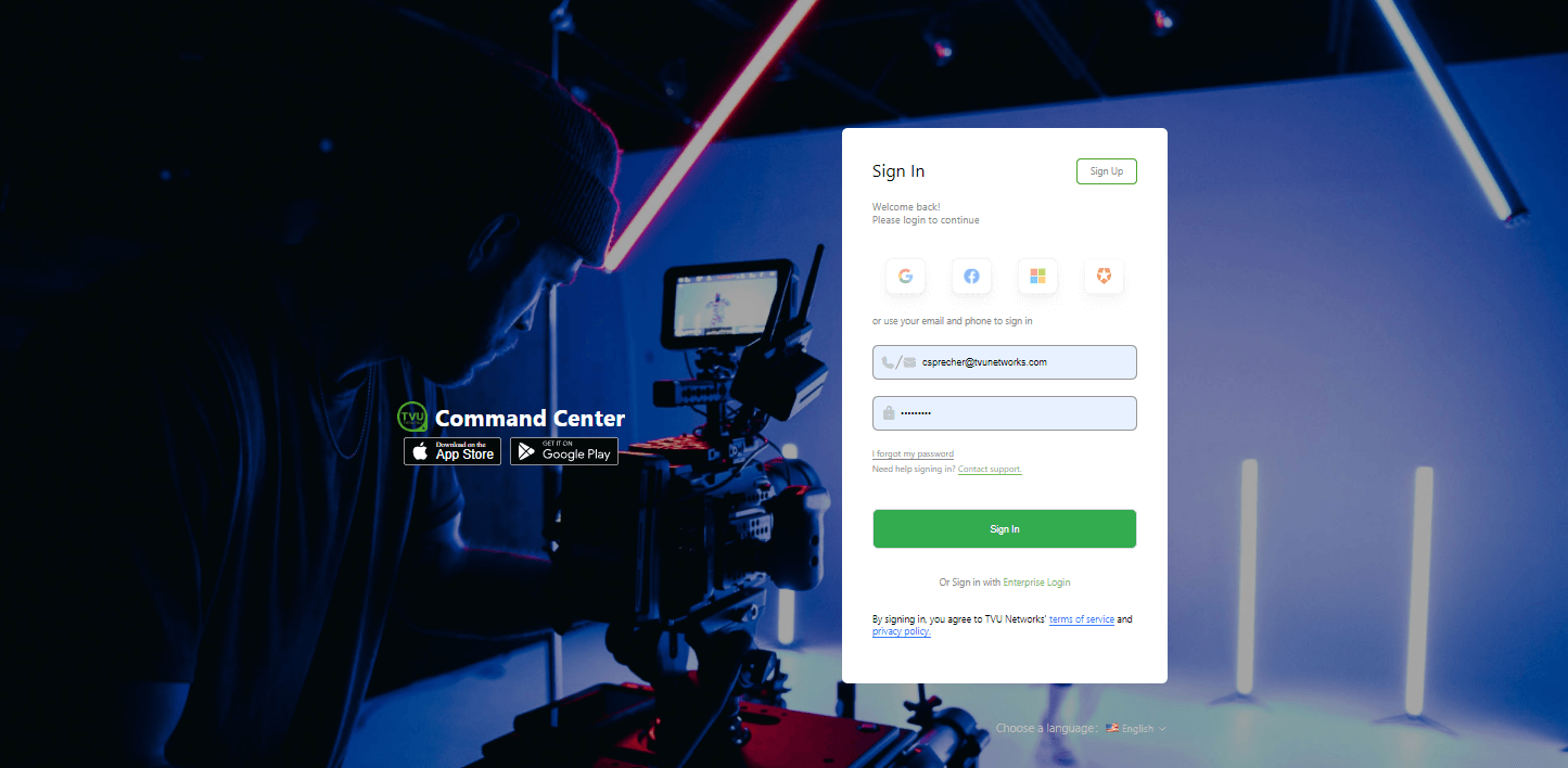
TVU Networks makes it easy to sign up for a Command Center account. From the TVU Networks website, click the Sign up/Login button at the top of the page. On the Sign in page, click Sign Up, enter the required fields, click Get Started Now, and follow the registration steps.
This TVU Command Center User Guide provides an overview of the new user interface and instructions for setting up and using the TVU Command Center’s basic and advanced operations.
Features
TVU Command Center’s robust cloud-based toolset comes with the following features:
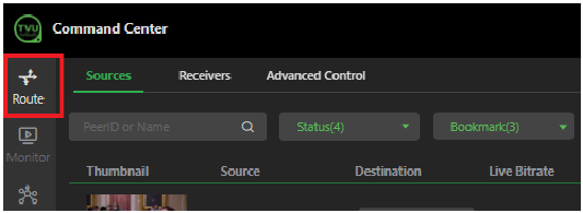
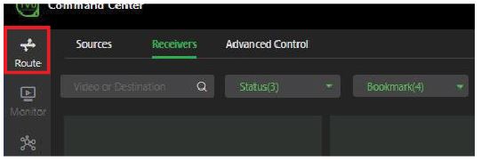
Route tab – The Route tab has the following features:
The Route tab displays paired receivers and available sources. Users can select one or more receivers and go live with available sources from this tab.
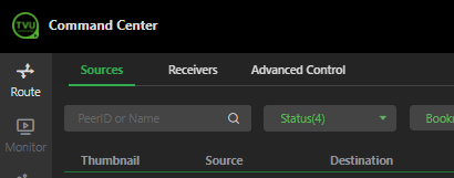
Sources: The My Sources page is accessed by selecting the Route tab in the left panel and the Sources tab in the top navigation panel. Sources can be displayed by status, bookmark, type, by name, Live first, or by which source was online first.
Receivers: Users can access the Receivers page by selecting the Route tab in the left panel and selecting the Receivers tab in the top navigation panel. The Receivers page displays receivers paired to their account. Users can click the source drop-down menu below the preview to select and go live with a source associated with that receiver.
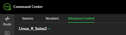
Advanced Control: The Advanced Control page is accessed by selecting the Route tab in the left panel and the Advanced Control tab in the top navigation panel. The Advanced icon on the Receivers page also opens the Advanced Control page, which includes the Source panel. It also displays the Settings, control, and diagnostic data for a selected source.
Multi-Control feature: The Multi-Control feature allows synchronization of up to twelve TVU transmissions on the same delay by enabling Time Lock. The Multi-Control page is accessed by selecting the Route tab and Receivers tab from the top navigation panel and clicking the green Multi-Control button.
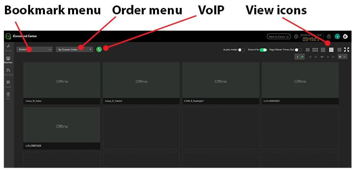
Monitor tab: The Monitor tab allows users to watch full-motion live videos of their current live receivers in a multi-view format without timing out. Users can listen to the output audio, view individual windows full screen, and use VoIP controls to communicate with each receiver’s TVU Pack.
Grid tab: The new TVU Grid for Command Center features allow TVU Command Center account owners to access and manage Grid sources outside their traditional organizational boundaries.
Token tab: The TVU Anywhere app integrates with the token feature, allowing an operator to automatically pair receivers without intervention from TVU Support.
RPS One tab: Command Center supports an RPS One 4-channel transmitter source. The RPS One tab allows users to enable Source Switch mode.
Chat feature: Contact the TVU Support team via chat within the new Command Center user interface.
Alert icon: TVU Command Center Alert feature allows users to send alerts about sources or receivers to other Command Center accounts with access to those devices.
Setting icon: Access all features and system settings enabled to display in the Settings menu.
Social Accounts tab: The TVU Share feature enables users to share or publish a source directly to a social media account or website.
User preferences: Full control of TVU receivers, including Geo-locate, a GPS-based map view of all powered TVU transmitters.
Tracking and location features: Track TVU receivers, including Geo-locate, and show a GPS-based map view of all powered TVU transmitters.
TVU Pack battery level notification: The Command Center interface will display an alert and a battery low indicator when a Pack reaches a critical battery level of 5%. The pop-up clearly identifies the specific Pack(s) with the critical battery and provides hotlinks to the corresponding Packs’ “My sources” entries.
Battery Status indicator: When a paired device battery is low, users will hear a “beep” and a Battery indicator message at the top right of the Command Center window appears.
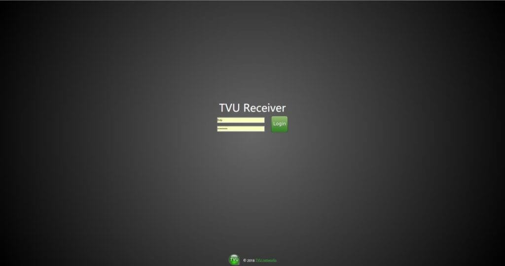
Logging in to the TVU Command Center Web User Interface
To sign in to Command Center, complete the following steps:
To Sign in to the TVU Command Center Web user interface, enter your email and Password.
Click Sign in.
TVU Command Center User Interface
This section describes the new TVU Command Center user interface’s four main tabs in the left panel:
Route tab – All transmissions can be managed from the Route tab. The Route tab displays paired receivers and available sources. Users can select one or more receivers and go live with available sources from this tab. Sources can be filtered by status, bookmark, type, and by name, or by which source was online first. The Setting page can be accessed by clicking the gear icon in the bottom-left corner of the advanced receiver page.
Monitor tab – The Multi-view page has been renamed as Monitor. The integration of the TVU Multi-view feature enables previewing six live video streams on a single monitor. The TVU Multi-view feature is available to monitor more than six live video streams on a single monitor. Select the display matrix, and if the number of monitored videos exceeds the matrix’s maximum, you will see pagination.
Grid tab – The Grid tab gives the user complete control over all TVU Grid video content switching, routing, and distribution.
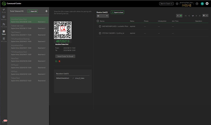
Token tab – Select the Token tab to share the QR code with others for TVU Anywhere pairings. Using the Token tab feature, the operator can perform automatic receiver pairing without the intervention of TVU Support.
RPS One tab: Command Center supports an RPS One 4-channel transmitter source. The RPS One tab allows users to enable Source Switch mode. Users can switch 1, 2, 3, or 4 on the touchscreen to output to a single receiver. All video formats and frame rates must be the same to use this function in Command Center.
TVU Command Center User Interface Route tab
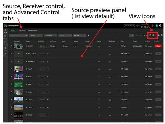
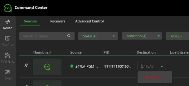
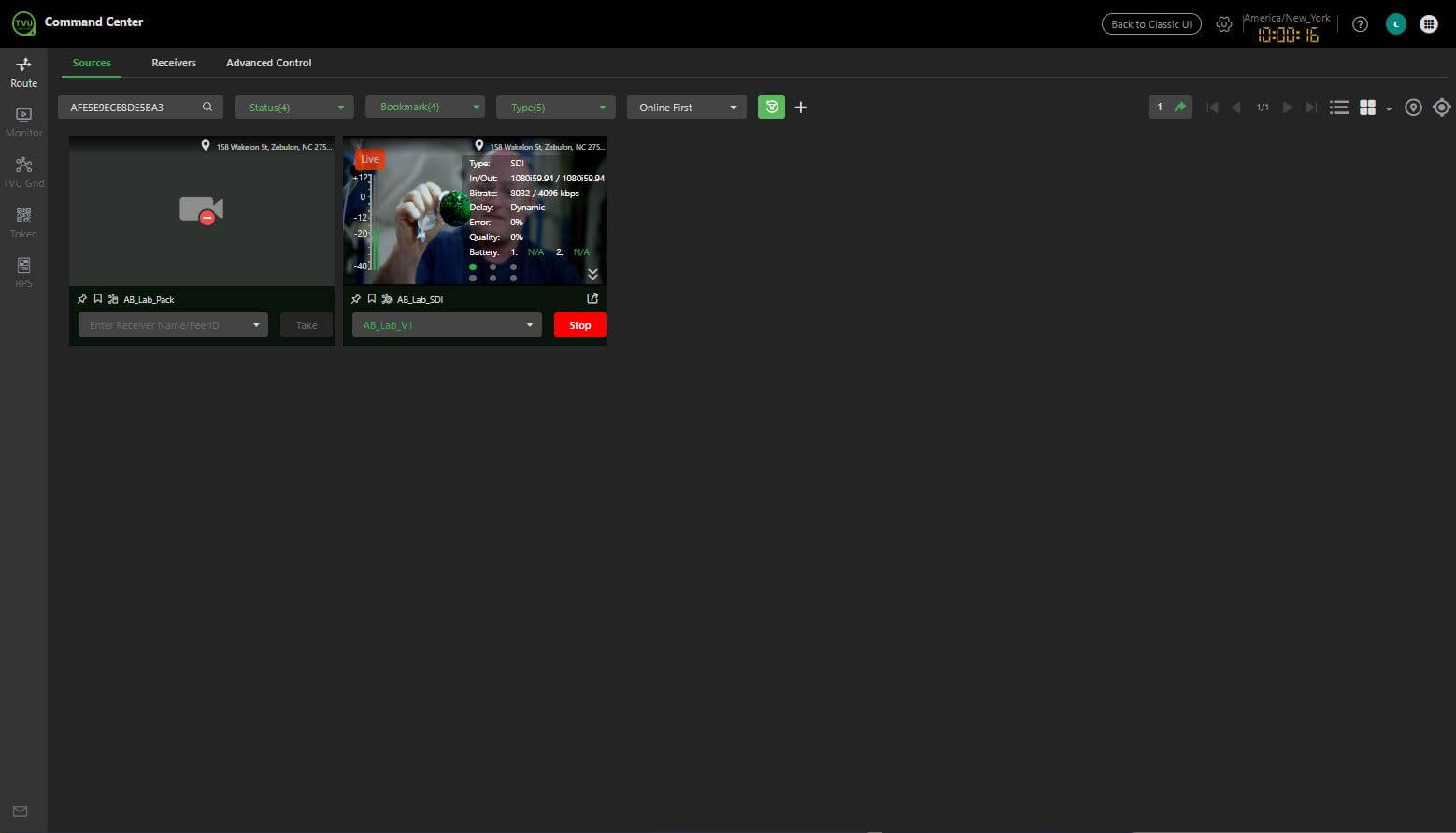
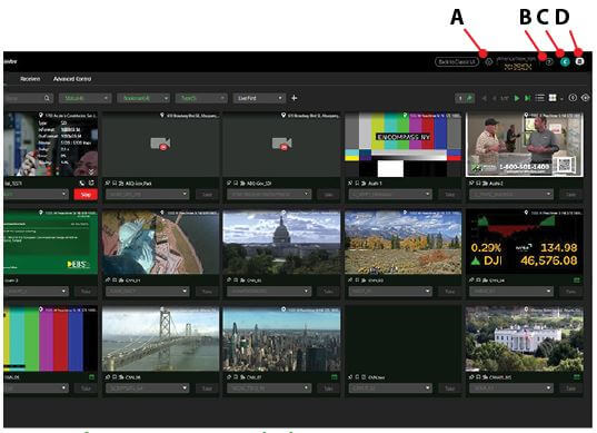
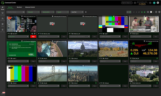
After a successful login, the TVU Command Center Web user interface Route tab and Sources page will be displayed by default.
By default, the Source tab displays source thumbnails in the list view. Users can rearrange the columns by clicking the vertical three-dot menu in the window’s top-right corner. You can also shuffle the columns by dragging and dropping the column titles.
Users can also change the “Sources” view from gallery preview to list view by clicking the view icons in the window’s top-right corner.
The Route tab > Sources tab provides an efficient way to access sources and receivers.
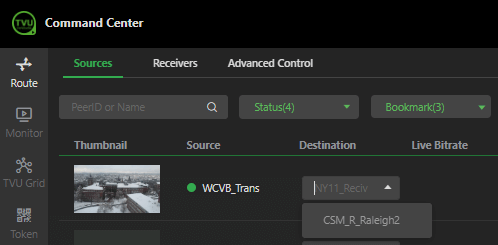
Available sources are displayed with a green status indicator.
The drop-down menu to the right of the source preview displays the receiver paired with the source.
Use the top drop-down menus in the top navigation panel to display sources and receivers in a sortable list.
Users can select a source from the source or receiver window to open the expanded source window. Use the drop-down menu in the highlighted column to change the destination receiver for the selected source. To take the source live, click the Go Live button.
Receiver selection menu
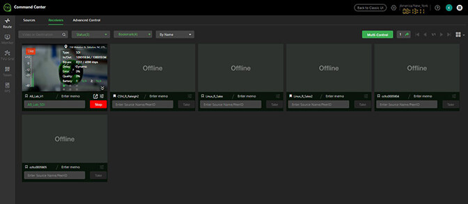
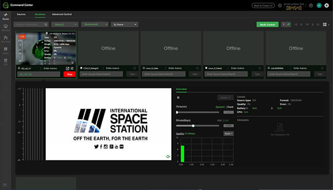
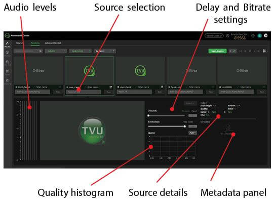
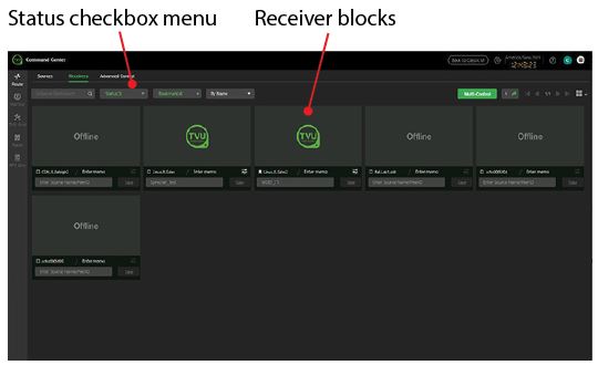
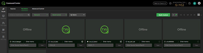
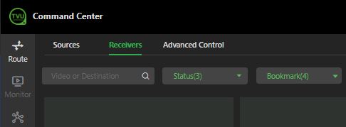
The Receivers page displays a sortable list of receivers paired with a user’s Command Center account. Select the Route and Receivers tab in the top navigation panel to open the Receivers page.
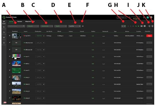
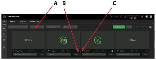
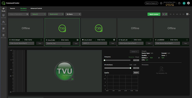
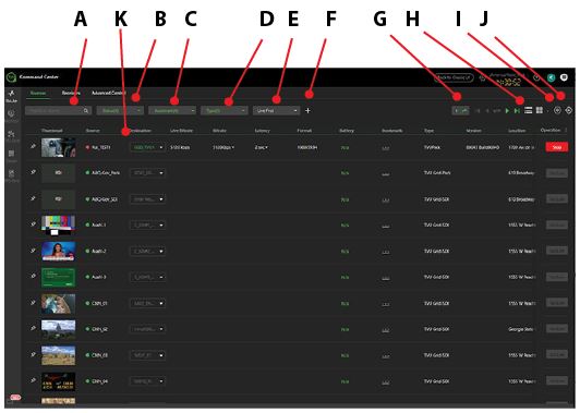
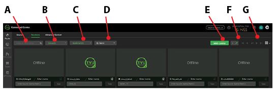
Receiver page controls and functions
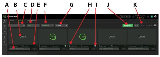
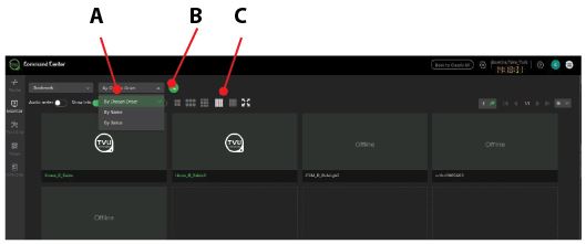
(A)Source selection menu: Select a source from the drop-down menu to go live with.
(B) Click the video preview to open the expanded receiver control panel.
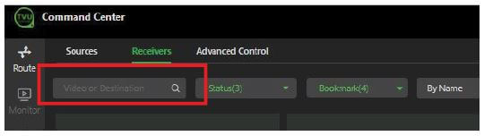
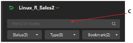
(C)Search: Enter the Video or Destination in the search bar.
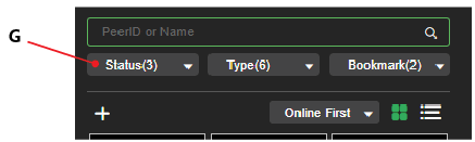
(D)Sort by Status: Click the Status menu to sort your receivers by their status. Checking the Status checkbox in the drop-down menu allows users to sort and display receivers by their current status.
(E)Publish icon: The publish icon enables users to publish an output video stream to a Website of their choice.
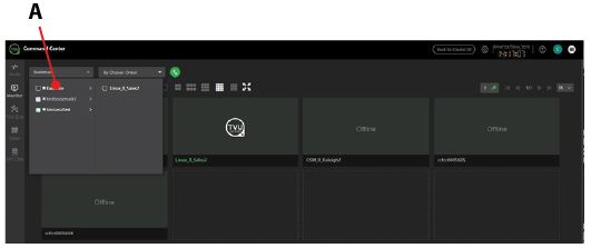
(F) Bookmark Menu: Preset bookmarks display and can be selected from the Bookmark drop-down menu in the Sources and Advanced top-navigation windows.
(G) Receiver filter menu: This menu allows users to sort receivers By Name, Online First, and Live First.
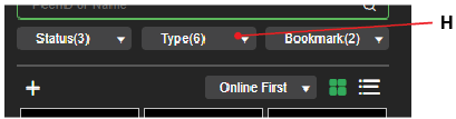
(H) Bookmark icon: Click the Bookmark icon to create a preset bookmark for a specific receiver. Clicking the Bookmark icon lets you designate that receiver as a favorite. Selecting the My Favorite checkbox in the top navigation will sort and show only favored receivers in the results.
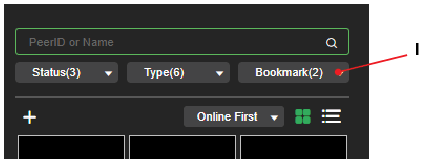
(I) Advanced icon: The Advanced Control icon opens the Advanced Control page, where users can access the source panel, preview a source selection, and access the Setting menu.
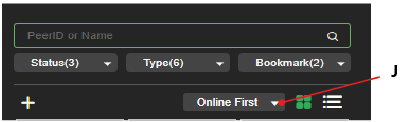
(J)Multi-Control button: The green Multi-Control button opens the Multi-Control window.
The Multi-Control window includes the following controls and functions:
Notes:
Timelock is only available when all selected receivers are live with a TVU Pack.
(K) Page Navigation: Click the navigation buttons to flip through multiple pages of sources, go to a specific page, or skip to the last page.
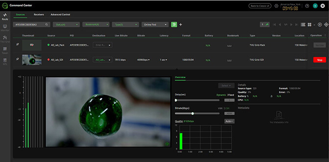
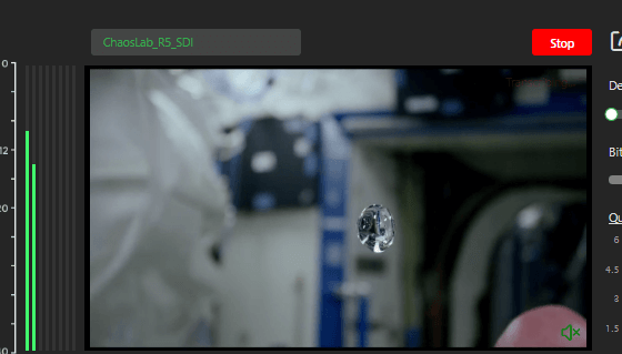
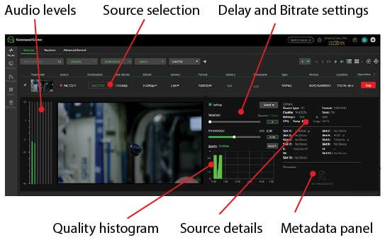
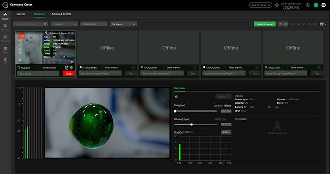
The Expanded Receiver Control page includes the following controls and functions:
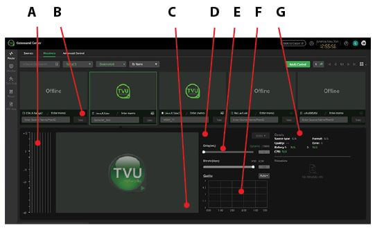
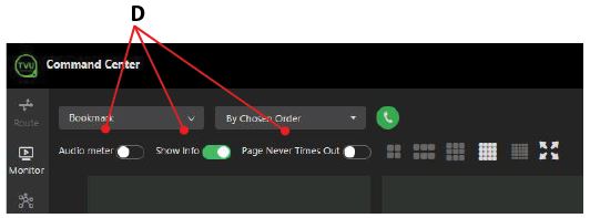
(A)Audio bars: Provide a visual indicator of the video stream’s audio output.
(B) Stop button: Click the red Stop button to stop a live source.
(C) Audio mute icon: The speaker icon will allow users to enable or disable the audio output without affecting the actual audio output of the stream.
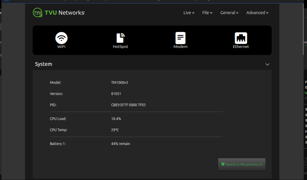
(D)Extended receiver information icon: Click the “i” icon next to the receiver name to display information about the receiver, including PID and software version.
(E)Delay and bitrate control settings: These sliders control a TVU Pack stream’s bitrate and delay settings.
(F)Quality histogram: The Quality histogram displays the live transmission status.
(G) Source transmission diagnostics: Displays “Details” that represent the health and format of a source and its transmission. Battery, error rate, and line quality will only populate for a TVU Pack transmission.
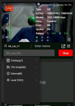
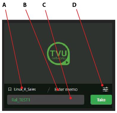
Receivers page preview block
The receiver preview block has elements that should already be familiar to you, such as the receiver name, source selection drop-down, and the Take (Live) button. We have added new functional elements to the source preview block, which include bookmark settings, my favorites (heart), memo text box, and the Advanced icon.
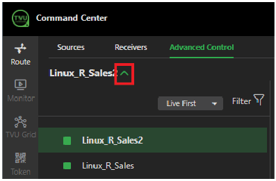
The Advanced icon is located in the Receivers page preview block. When a receiver is online, the Advanced control icon in the source preview screen turns white. When the receiver is offline, this icon is grey.
Click the “Advanced” icon to display the Advanced Control page for that specific receiver.
Note: Refer to the Advanced operations “Advanced Control page” for more information about Advanced features and functions.
Note: The Advanced Control page can be opened using the Advanced icon or Advanced Control tab.
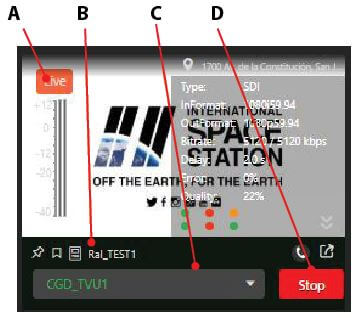
The source video preview block controls and functions (when Live) are described as follows:
(A)Source status indicator: The Source indicator displays “Live” when the source is live.
(B)Receiver name: Your selected receiver name is displayed in this field.
(C)Source selection drop-down menu: Click the source drop-down menu to view the source and receiver you have gone live with.
(D) Stop button: Click the Stop button to stop the transmission.
(E)Expand info icon: Click the Expand info icon to expand a view containing the information you already know. The Modem status indicators are at the bottom. These show the current connection status of each modem in your TVU Pack. Starting at the top and from left to right, the modem order is Top: 1>2>3 and bottom: 4>5>6.
Modem Colors:Grey = offline, Red = no connection, Yellow = connecting, Green = connected.
Click the source preview to open the expanded version of the receiver thumbnail. In this view, you will see live moving video. There is also a mute button in the bottom-right corner of the expanded live video window. The control panel allows you to adjust bitrate, delay, VBR/CBR, and dynamic or fixed delay.
The Live preview panel displays an Info icon that opens a panel showing the receiver’s status information.
Note: Refer to “Expanded Source Control panel” for more information about the expanded receiver control settings and functions.
(F) VoIP icon: Starts a VoIP call between the receiver and a TVU Pack.
(G)Publish icon: Click the Publish icon to publish your output video stream to a Website of your choice.
(I)Bookmark icon: Click the Bookmark icon to add a bookmark to the source.
(J) Pin icon: Click the Pin icon to filter up to 10 source blocks to sort, group, and display them together.
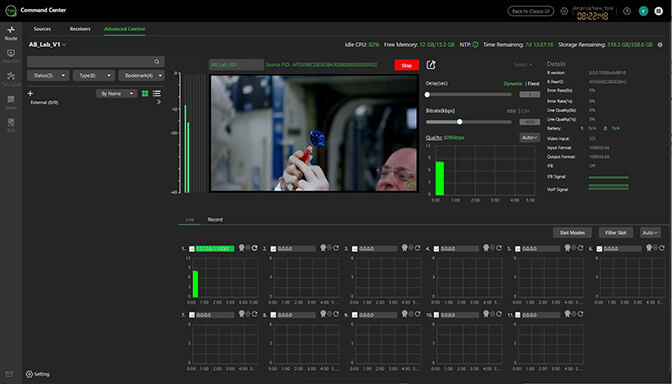
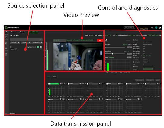
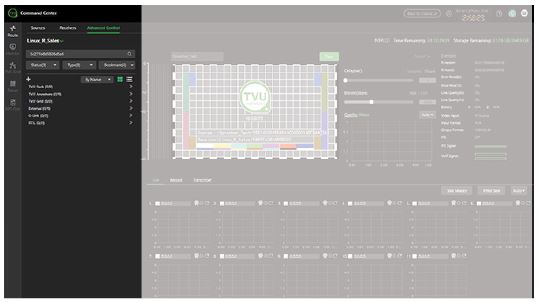
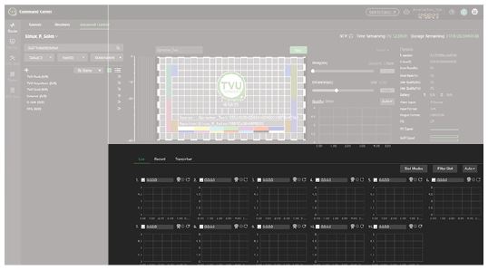
Advanced Control page
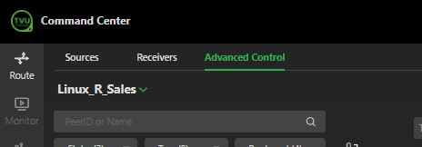
To open the Advanced Control page, select the Route tab, then the Advanced Control tab in the top main navigation panel. Alternatively, users can click the Receivers tab and the Advanced icon located below a specific receiver preview. Note that clicking the Advanced icon opens the Advanced Control page for that specific receiver.
The Advanced Control page includes the following operational panels:
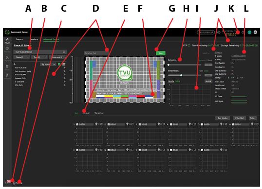
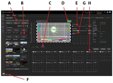
The Advanced Control page includes the following operational controls and functions:
(A)Search bar: Search for a source name or PeerID.
(B)Source selection menu: This section contains all available sources for the selected receiver, filtering, and search options—sort sources by Status, Type, and Bookmark.
(C)Video preview panel / Audio mute icon: The Speaker icon will enable or disable audio output to your PC. This icon does not affect the actual audio output of the stream.
(D) Quality histogram: This histogram is a live-updating graph that displays the data throughput of the current transmission as the receiver receives it.
(E)Live preview and Take/Stop button: Click the red Stop button to stop a live source.
(F) Publish icon: Click the Publish icon when live and you want to output to a Social media account.
(G)Source transmission, monitoring, and status: This panel allows editing of the bitrate and delay of a TVU Pack stream transmission. Metrics that represent the health and format of a source and its transmission also displays. Battery, error rate, and line quality will only populate for a TVU Pack transmission. You can also find the receiver PID in this section.
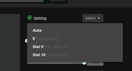
(H) SystemSetting: Mouse over the gear icon to expand a drop-down menu that shows available transmission settings for your selected receiver.
(I) Alert: TVU Command Center Alert feature allows users to send alerts about sources or receivers to other Command Center accounts that have access to those devices.
(J) Setting (feature control): Mouse over the gear icon to expand a drop-down menu showing available configuration options for your selected receiver.
Note: Refer to “Settings” for detailed information.
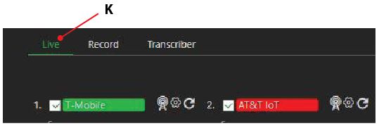
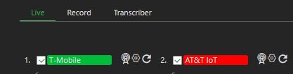
(K)Live, Record, and Transcriber mode tabs: These tabs control the content displayed below them. Live mode shows the individual modems for the transmitter and their current status. Record mode shows the console for managing recorded content for the selected transmitter. If the Transcriber is enabled, operators can use the real-time speech-to-text transcribing service.
(L) Audio Bars: Provides a visual indicator when there is audio with the video stream.
(M)Delay and bitrate control settings: Use these sliders to adjust the delay and bitrate of a TVU Pack stream.
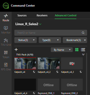
Source panel functions
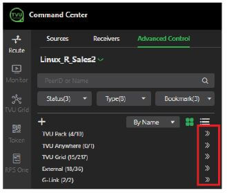
The receiver selection and sources panel is located in the left panel of the Advanced Control window.
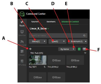
The Source panel includes the following controls and functions:
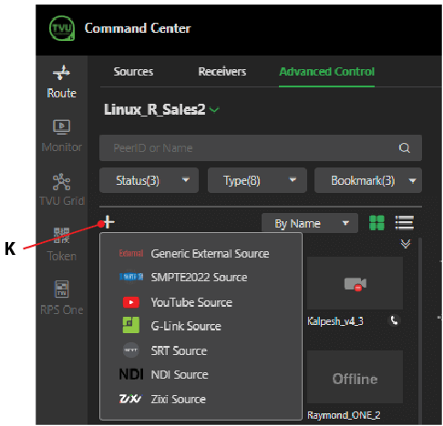
An operator can choose which source types to display by expanding the source menu carets.
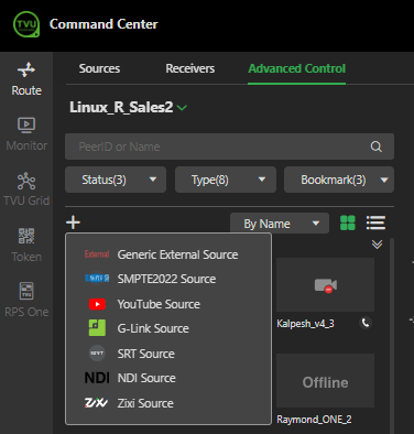
(A) To choose an external source, click the plus “+” icon. Available external source types are Generic External, SMPTE2022, YouTube, G-Link, SRT, NDI, and Zixi.
Located below the search field in the Source panel are three drop-down menus: Status, Type, and Bookmark. These menus have the following functions:
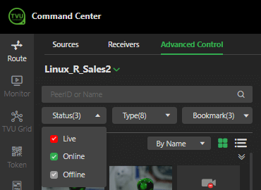
(B) Click the Status drop-down menu to filter, display, and select any source by Live, Online, or Offline status.
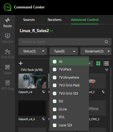
(C) Click the Type drop-down menu to filter, display, and select any source by type. Source types include TVU Pack, TVU Anywhere, TVU Grid-Pack and Grid-SDI, External, G-Link, RTIL, and Local SDI sources. To show all available source types, click the Type menu and select All.
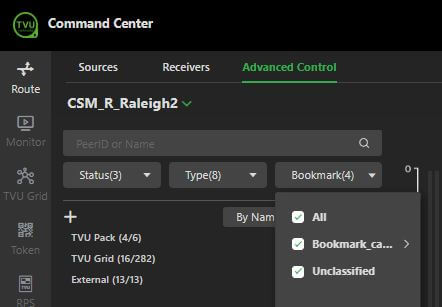
(D) An operator can filter, display, and select bookmarked source types by clicking the Bookmark drop-down menu.
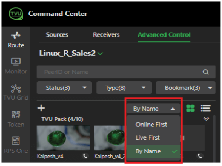
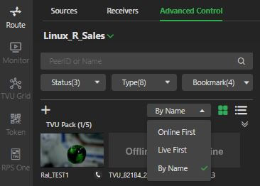
(E) An operator can filter and display source types by their status by selecting By Name, Online First, or Live First from the drop-down menu.
(F) View sources by thumbnail preview or list: These features allow the operator to display all TVU transmitters and their status in a graphic thumbnail or by list.
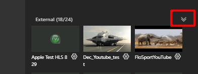
Source thumbnail indicators and functions
To open the source information panel, click the caret. External sources display with a gear icon below the preview thumbnail.
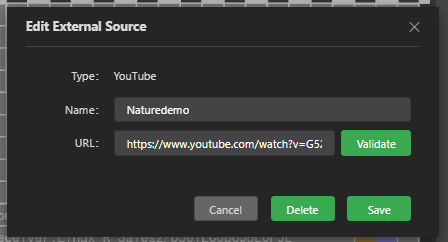
Clicking the gear icon below the video thumbnail opens the Edit External Source window, which allows users to edit and validate the external source.
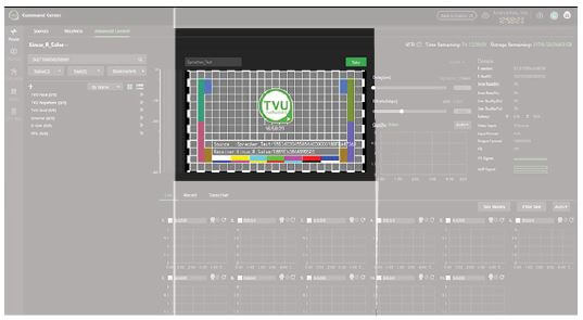
Video preview panel
The video preview panel shows the live video output state or the offline state previews. When a video is live, the operator can mute or unmute the audio by clicking the speaker icon in the bottom-right corner of the preview screen.
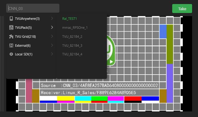
When a source is live, the video preview displays in the preview window. To stop the transmission, click the red Stop button.
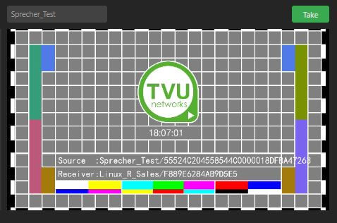
When a source is not live, the video preview displays the following TVU slate and a green Take button.
Take/Stop button: The Take/Stop button lets the operator stop or restart a live transmission from a selected source.
Data transmission monitor panel
The data transmission monitor panel is located below the preview panel.
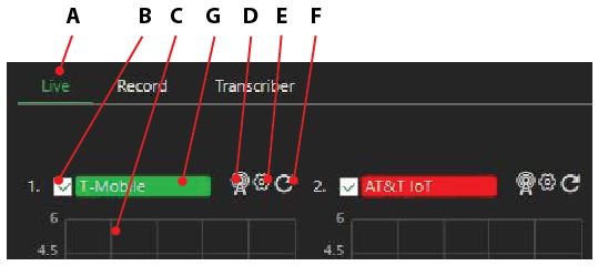
The Live tab displays the data transmission monitor panel, which includes visual modem histograms with the following controls and functions:
(A) Live, Record, and Transcriber tabs: These tabs control the content displayed below them. The Live mode is the primary interface used during a Live transmission. When this tab is selected, the status of each data card network connection will be displayed. Record mode will show the console for managing recorded content on the selected transmitter. Operators can use the real-time speech-to-text transcribing service if the Transcriber is enabled.
(B) Check box: A check box and status bar are associated with each card. The check box enables or disables a data connection. If unchecked, it will not be used to pass data. If the box is checked (default), the connection will be used to pass data.
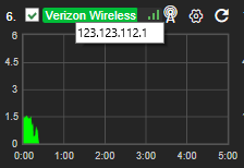
(C) Connection name and status: Individual read-out panels show each active card’s carrier name (when available). The slot number of each data card is indicated in front of the carrier name. To retrieve the IP Address of a data card, mouse over the name of that data card. You can enter your preferred <name> if no name is automatically provided and displayed. However, this will reset upon reboot.
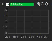
The color indicators displayed within the carrier name panel indicate the following status:
Red: Not connected or dialing
Green: Connected and passing traffic
Yellow: Connected but not passing traffic
Gray: Disconnected or unplugged
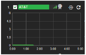
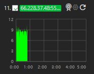
(D) Monitor histogram: The monitor histogram displays each modem’s status, throughput, and IP address.
(E) Connection mode and connection strength indicator: The connection mode indicates the connection mode and strength.
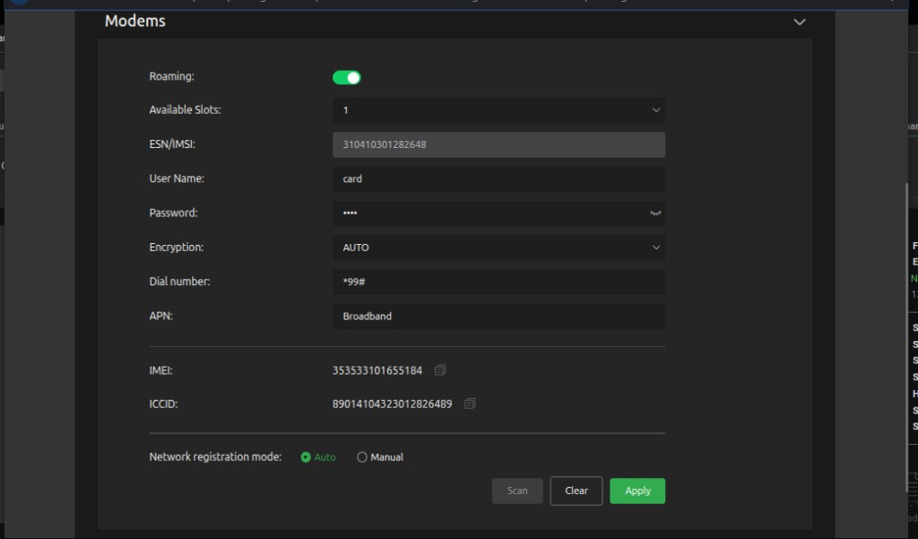
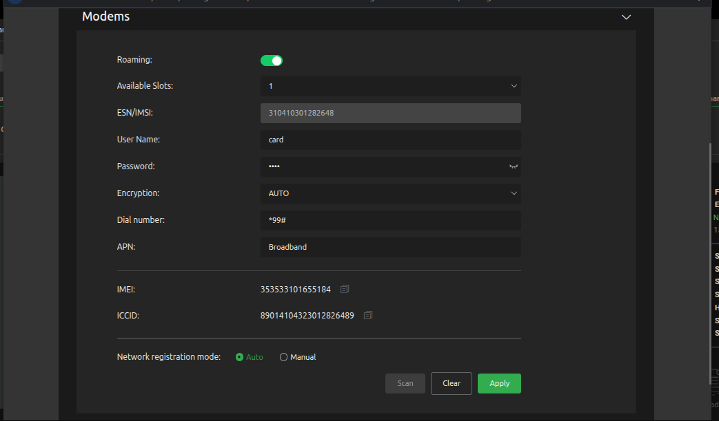
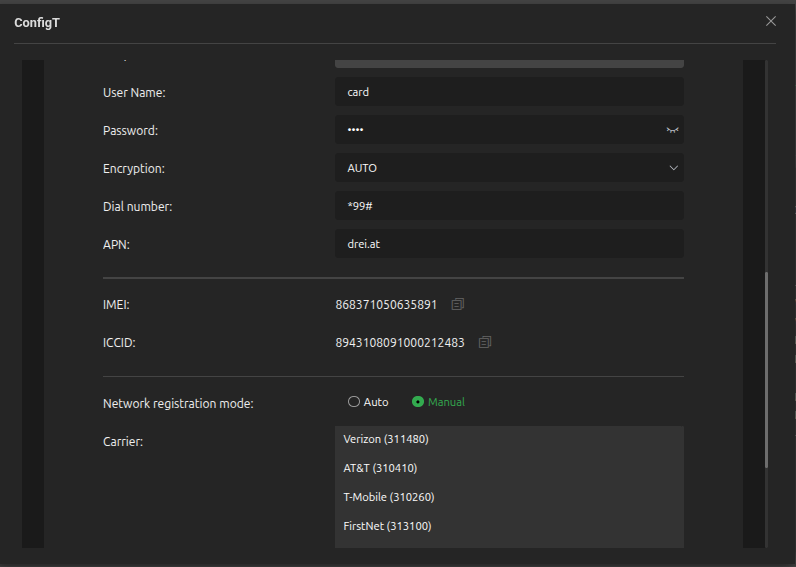
(F) Configuration menu: Opens the Web UI of the pack source.
(G) Reset: Provides a full-power reset for a modem. This feature is used when the modem cannot connect or is experiencing issues. Click the Reset icon to force the modem to power cycle and reset.
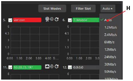
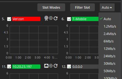
(H) Scale: The Auto drop-down menu lets the operator set the histogram scale. When the scale changes, it affects all displayed histograms.
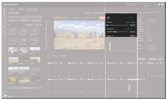
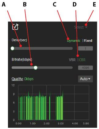
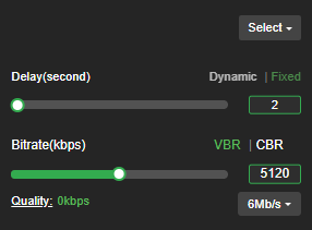
The Controls Setting panel is located on the Advanced Control page.
The setting panel includes the following controls and functions:
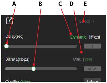
(A) Delay control: Set your desired latency and the maximum bitrate you want to utilize. When in “Live” mode, the error rate and picture quality will automatically adjust based on the desired latency and available bandwidth to deliver the highest-quality picture.
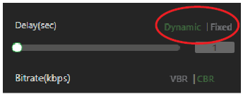
(B) Bitrate control: The TVU receiver has a smart VBR scaling system. The unit automatically adjusts the bitrate to output the best quality picture based on the desired latency. To effectively leverage the smart VBR scaling system, set your desired latency and the maximum bitrate you want to use.
(C) Adaptive delay control (Dynamic/fixed) for Grid only: Controls the dynamic buffering, which is a Grid feature. When set to dynamic mode (recommended), the receiver automatically increases the stream buffer to ensure stable transmission. This selection maximizes stream stability but may increase delay/latency. The fixed mode locks the Grid stream to a specific delay but allows errors if the setting is too aggressive. It is recommended to use dynamic mode by default. When fixed mode is enabled, the operator should pay close attention to stream stability with their current settings.
(D)VBR/CBR: The TVU receiver has a smart VBR scaling system.
(E) Preset selection menu (operational): Click the Select drop-down menu to view mode selections. Depending on your news-gathering environment, you can choose from preset bitrates and latencies.
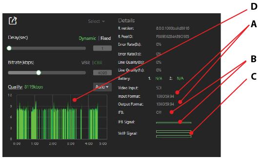
Many indicators are arranged vertically in the Status panel to help an operator make quality and troubleshooting decisions. Information such as error rate and line quality is displayed, and a quality histogram depicts the total transmission encoding bitrate over a period. The histogram’s scale can be changed by selecting a different display option from the drop-down menu. The status of the transmitter’s batteries is also displayed.
The Status panel diagnostics are shown below.
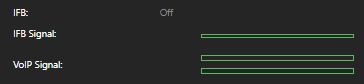
The Status panel includes the following controls and functions:
(A) Input and output formats: “Input” displays the video input format of the transmitter. “Output” displays the receiver output setting.
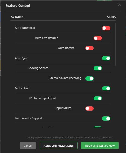
Note: The receiver output format follows the input format. When the Input Match feature within Feature Control is enabled.
The TVU Pack input and receiver output should match. The receiver software is not intended to convert or adjust the resolution. In the event of a mismatch, the receiver will attempt a format conversion, which may result in a loss of video quality and the removal of closed captions from the transmission.
(B) IFB status: Displays the IFB status and the IFB Signal. The IFB signal has a strength meter that indicates the IFB input level.
(C) VoIP status: The VoIP Signal has a strength meter that depicts the input level. (D)Quality histogram/Quality link: The quality histogram below the Quality link displays a 5-minute aggregate histogram of the live transmission.
Sources page
The Sources page is accessed by clicking the user interface Route tab. The Source page displays source thumbnails in the list view by default.
Users can rearrange columns by clicking the vertical three-dot menu in the top-right corner of the window. You can also shuffle the columns by dragging and dropping the column titles.
The sources preview panel includes the following controls and functions:
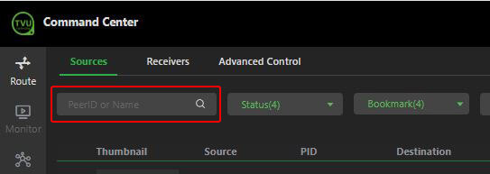
(A)Search: Enter the source PID or Name in the search bar to locate a source.
(B) Status: Click the Status drop-down menu to display sources based on the source types you select in the drop-down menu.
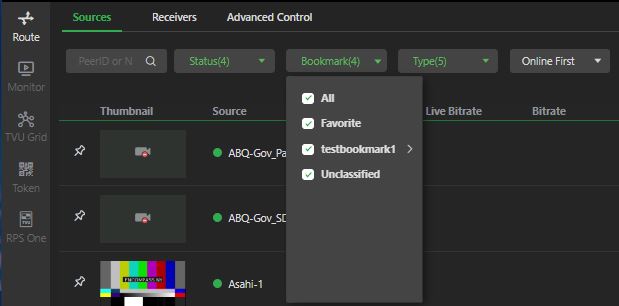
(C)Bookmark: The Bookmark drop-down menu can display special arrangements for receivers, including bookmark categories and favorites created by the user.
Note: the bookmark menu is hidden from new users and users who have not previously set up a bookmark category.
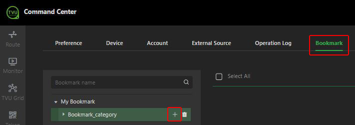
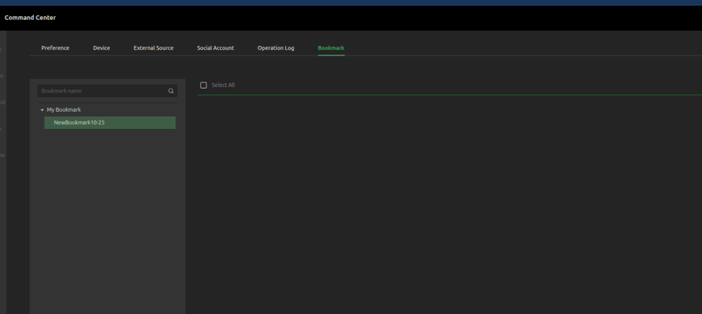
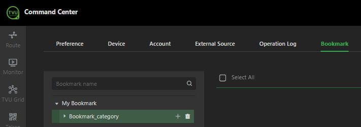
To create a Bookmark category
Click the Command Center Settings icon.
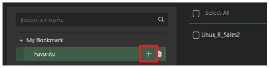
Click the Bookmark tab, hover the mouse over Bookmark, and click the “+”.
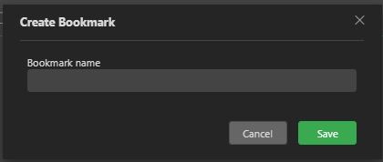
In the Create Bookmark window, enter a bookmark name and click Save.
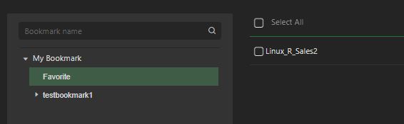
Your bookmark category displays below “Bookmark.”
The new entry will appear as a selection in the Sources and Receivers pages Bookmark menu.
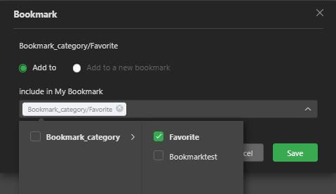
After creating a bookmark category, users can apply a Favorite bookmark independently to a receiver by selecting the Bookmark icon on the Receivers page.
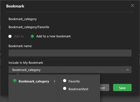
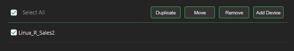
To apply a Favorite bookmark, click the Bookmark icon to open the Bookmark pop-up window. Select Add to, click the Favorite checkbox, and click Save.
Click Add to new bookmark to create and add to an existing bookmark in your list, then click Save.
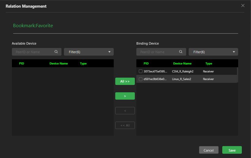
To add a device to your bookmark, refer to “To add a device to a bookmark.”
(D)Type: Click the Type drop-down menu to filter your sources based on type. The results displayed below the drop-down menu correlate to the selected checkboxes.
(F) Add external source: The plus + icon enables users to add an external source, such as a Generic External (Ext), SMPTE2022, YouTube, G-Link, SRT, NDI, or Zixi source. The added source displays in the source panel with the other source thumbnails.
(I) Source view options: These two icons will allow you to switch between a list view with a thumbnail or a video preview block. The default is the list with a thumbnail view. The list view will show you all of your filtered results and periodically update the preview thumbnail of the source’s content. It displays the source name and a status indicator to show if it is online, live, or offline.
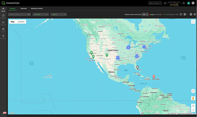
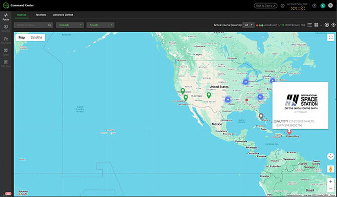
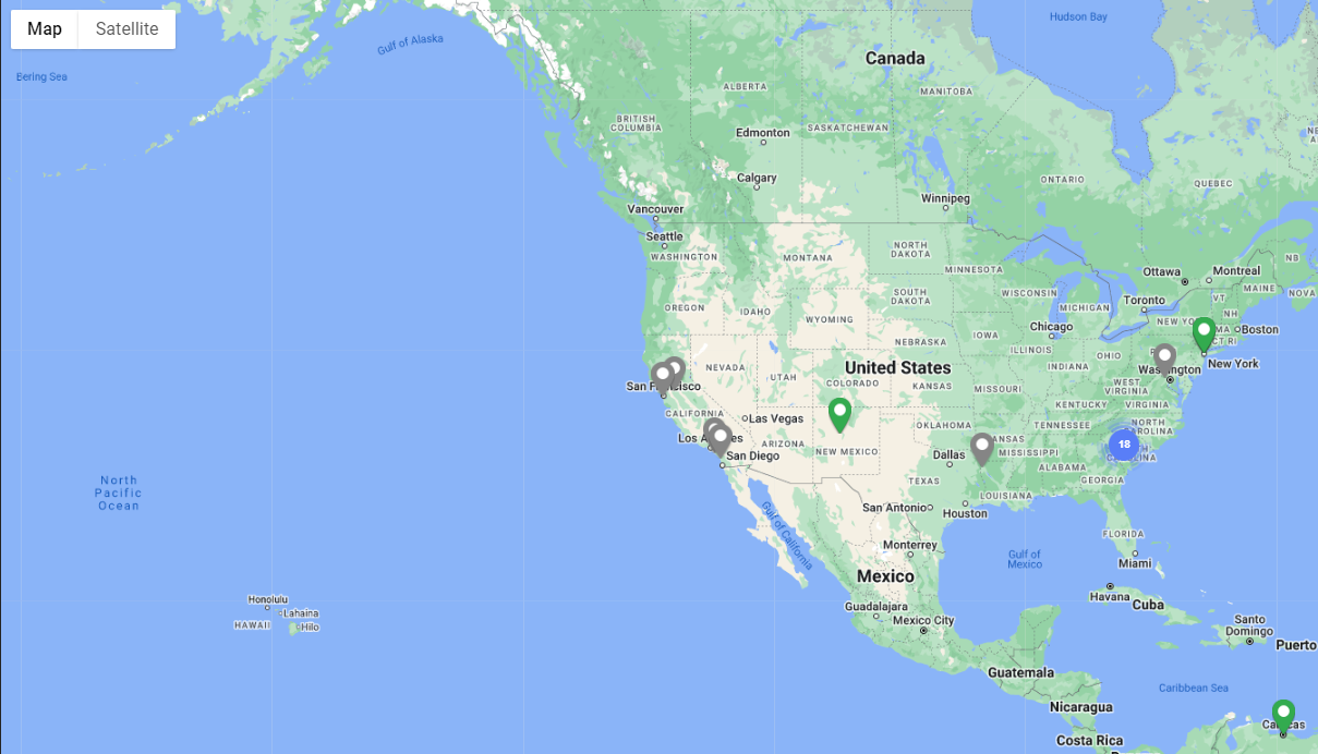
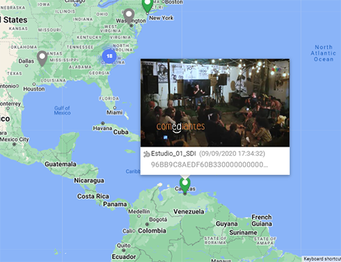
(J) Geo Location icon: Click the pin icon to open a geographic map showing the physical locations of sources and receivers.
Hover the mouse over a map pin to display the name of a source.
Click on a map pin to open a window showing a still capture of the source’s content and status. Additionally, the receiver that the source is live with will display as a red pin on the map.
To exit the map, click the block view or List view icon.
Note: Refer to “Source GPS locations, tracking, and previews” for more information about using the Geo location feature for a single source or receiver.
(K) Tracking icon: Click the Tracking icon to track a Pack or TVU Anywhere device in real time or by history.
User preferences
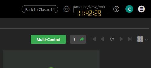
The Command Center’s main user preferences are located in the top-right corner of the user interface.
The user preference and main navigation panel include the following controls and functions:
(A)Setting icon: Click the Setting icon to change your settings.
(B) What’s New icon “?”: Click the “?” icon to see the latest product changes.
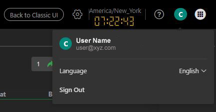
(C) User preferences: Click the user preference drop-down menu to choose a language and to log out of Command Center.
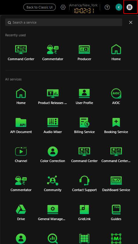
(D) Services navigation menu: Click the Waffle icon to access links to additional TVU Web services.
Expanded Source Control panel
Click a preview thumbnail to open that source’s expanded Source Control panel. The source control window works in the same way as the expanded Receiver Control panel, with source details and metadata to the right of the preview.
The sources in the Route tab look slightly different from the source views in the Receivers page. The receivers display as preview blocks. When you click a receiver preview, an expanded view of the source and a settings panel display the same information as the Sources control panel.
The Command Center Monitor tab replaces the Multi-view page. The Monitor tab provides users with the ability to watch a full-motion video of their Grid-related receivers that are currently live. Users can listen to the output audio, display individual full-screen windows, and use VoIP controls to communicate with each receiver’s respective TVU Pack. To remove a receiver from the Monitor view, hover your mouse over the preview and click the red “X.”
Note: Refer to “Monitor tab” for more information about using the Monitor tab operations.
Grid tab
The Grid tab allows users to request and share Grid sources.
TVU Grid services feature:
Self-service TVU Grid connects all TVU Grid entities regardless of station, group, affiliation, or location.
Grid availability of major Network news services over IP rather than satellite.
Search capability to help locate and take advantage of these services.
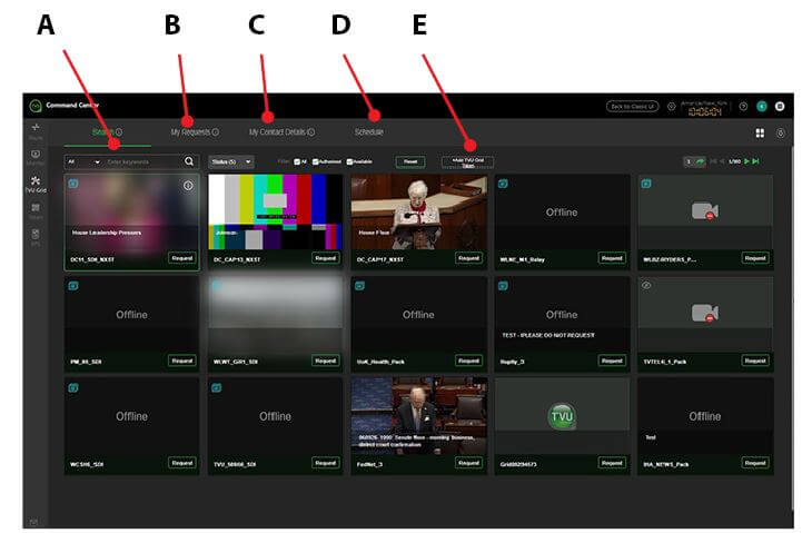
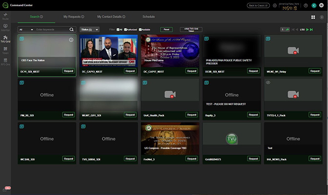
The Grid tab includes the following controls and functions:
(A)Search:
Find and control Grid sources you already have and don’t have access to.
Toggle between a thumbnail or map view to locate authorized and available Grid sources.
Filter your keyword search based on name, location, affiliation, and group.
Add Grid sources using a Grid Token code.
(B)My Requests:
View all of your direct and Grid Token access requests.
Control Grid sources that you have been granted access to via Direct Request and Grid Token.
Manage your Direct Request and Grid Token access requests.
Add Grid sources using a Grid Token code.
(C)My Contact Details: Configure your contact details so you can communicate efficiently with others and receive activity notifications.
(E) Schedule:
Use the Schedule tab to create a Grid source schedule by Month, Week, or Day.
Enter a title, date and time, reporter, and story slug directly in the calendar view.
Import a source event schedule from your local drive.
Download the slug information to your local drive.
(E) +Add Grid Token: Create a grid token.
Note: Refer to “Grid tab” for more information about using the Grid tab operations.
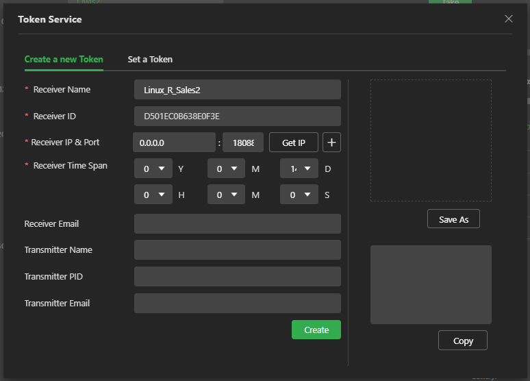
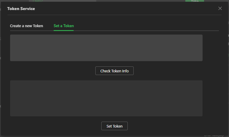
Token is a feature accessible by clicking the Token tab in the TVU Command Center User Interface. The TVU Anywhere app integrates with the token feature, which allows an operator to automatically pair a receiver without TVU Support intervention.
Using the TVU Anywhere token feature requires a token license activation from TVU Support.
The Settings gear in the top-right sources tab navigation allows users access to the following functional tab pages:
Preference
Device
Account
External Source
Operation log
Bookmark
Social Account
Access APP
License Feature report
Note: The Settings gear can be accessed in the top navigation panel of several other Command Center pages.
Click the Settings gear.
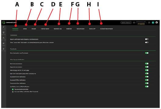
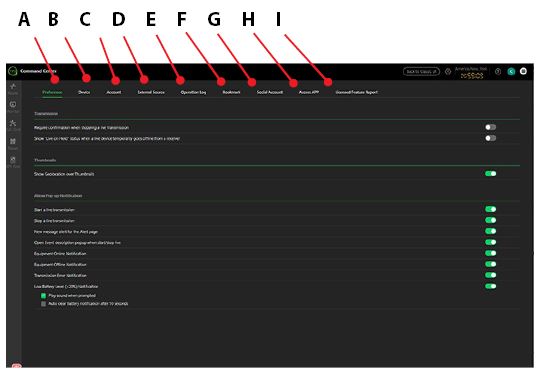
The Preference page Preferences tab opens by default.
(A)Preference: The Preference tab allows users to enable transmission confirmations, show Geo-location over thumbnails, and allow pop-up notifications for the Alert feature and when a transmission is live or stopped.
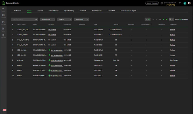
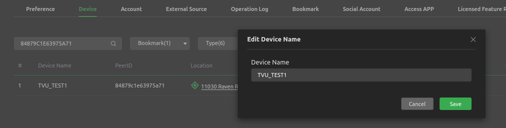
(B)Device: The Device tab displays a list of authorized receivers, their status, and version. The device name can be renamed here by selecting the edit icon in the right column.
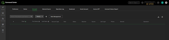
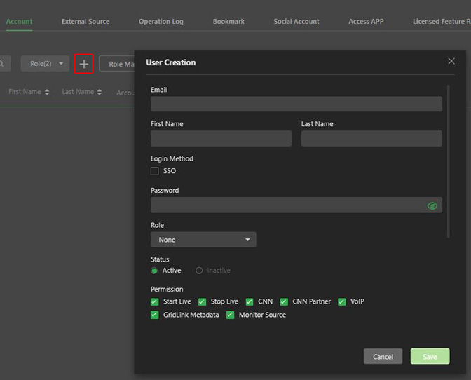
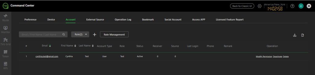
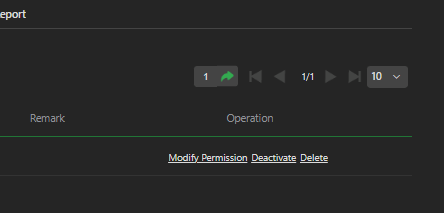
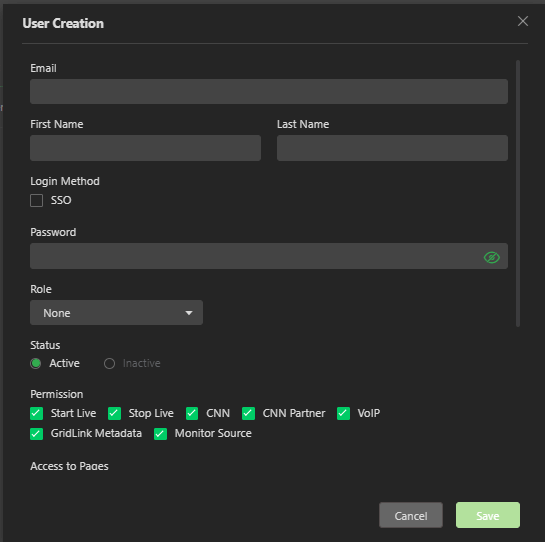
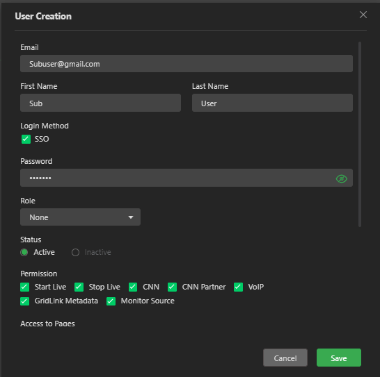
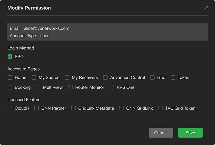
(C) Account: The Account tab allows the administrative account holder to create user-level accounts with and without SSO login credentials for their colleagues. The administrative account holder can set restrictions such as going live and stopping live, gaining access to specific receivers and sources, and gaining access to other features. In addition, the administrative account holder can assign a Co-admin role by clicking the Account tab Plus “+” icon to set up a new role, then Role Management button. Refer to “Creating a new user or Co-admin role” for more information.
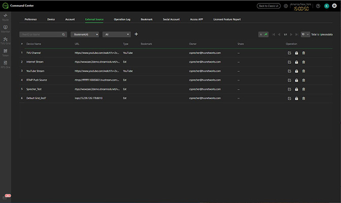
(D)External Source: The External Source tab displays a list of external source types by device name and URLs that have been accessed.
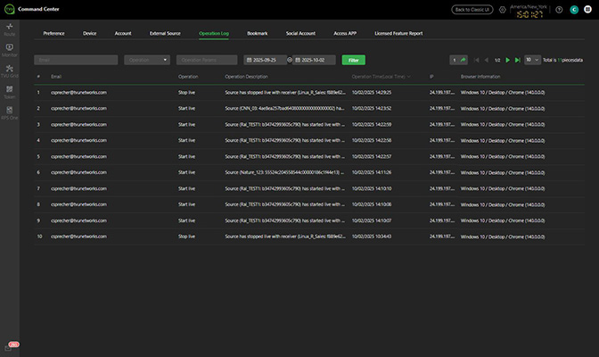
(E)Operation Log: The Operation Log tab displays the user’s operational status and descriptions by date, time, and IP address.
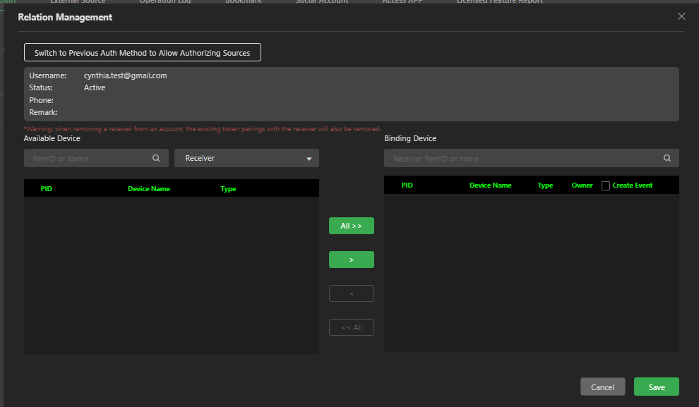
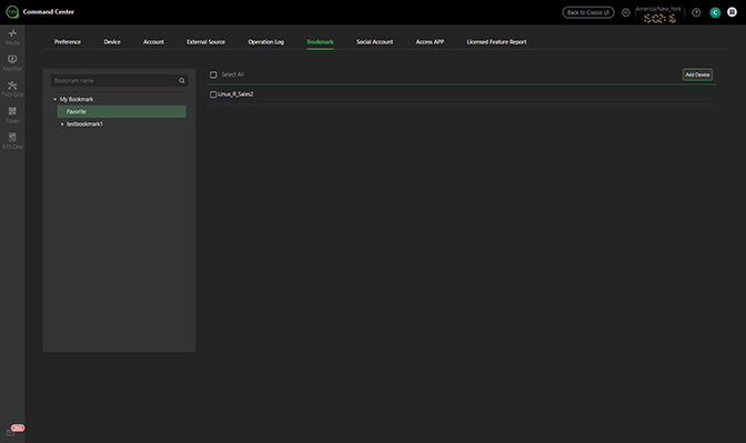
(F) Bookmark: The Bookmark tab allows users to view, select, and bookmark a Device in the Relation Management window.
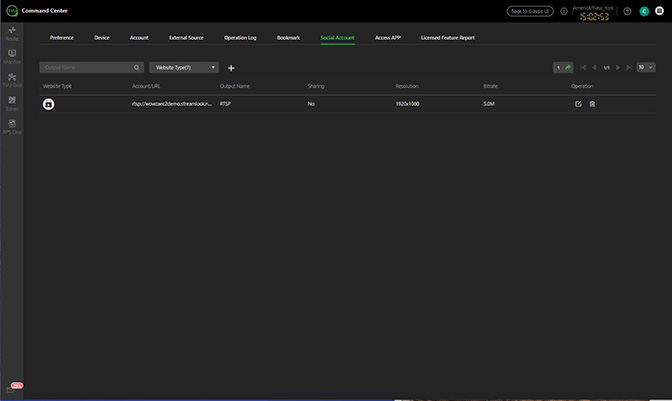
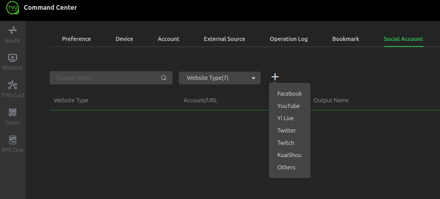
(G)Social Account: The Social Account tab allows users to configure Social Media CDN output accounts and lists the accounts they have configured. New accounts can be created by clicking the Plus “+” icon.
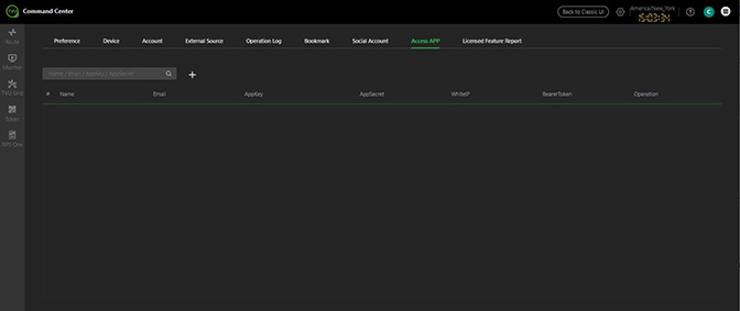
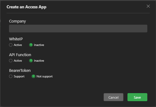
(H)Access APP: The Access APP tab allows users to search by company, email, Appkey, or AppSecret. Users can also create an Access App by company name and activate or deactivate the White IP and API functionality. In addition, a Bearer Token can be supported or not supported.
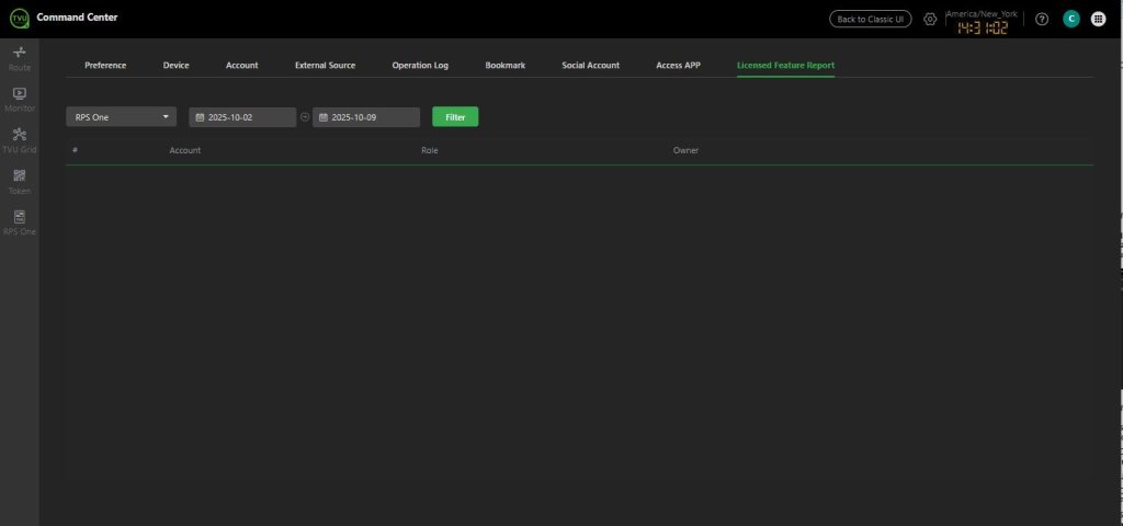
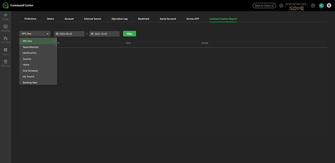
(I)Licensed Feature Report: The Licensed Feature Report tab provides a list of licensed feature owners, account, and their roles. The list can be filtered for a specific result.
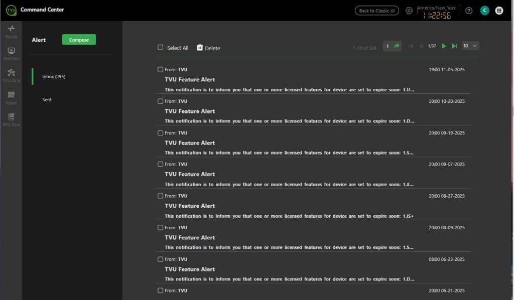
Alert feature
The Alert icon (mail) located at the bottom of the left panel on most pages provides support for TVU Analytics for full monitoring of data usage, including preset alerts for data usage thresholds. Click the Alert feature icon to open the Alert page, where the latest and sent alerts can be viewed and new feature alerts can be composed.
User settings, What’s new, preferences, and services menu
(A) Settings icon: Click the Settings icon drop-down menu to configure your setting preferences.
(B)What’s New feature: The What’s new (?) icon opens an overview of the latest Command Center enhancements and features.
(C)User Preferences: Click the user preference drop-down menu to choose a language and to Sign out of Command Center.
(D)Navigation menu icon: Click the Navigation menu icon to access links to additional TVU Web services.
Command Center receiver transmission – Going live
Taking your Command Center transmission live requires successfully signing into your Command Center account and performing advanced operations, which are explained in this section.
TVU Command Center User Interface
This section describes the basic components of the TVU Command Center user interface. The user interface left panel has five operational tabs:
Route tab – The Route tab manages all transmissions. It displays paired receivers and available sources. The user can select one or more receivers and go live with available sources from this tab. Sources can be displayed by status, bookmark, type, and name, or which source was online first. The Setting page can be accessed by clicking the gear icon at the top-right corner of the page.
Monitor tab – The Multi-view page has been renamed Monitor. Integration of the TVU Multi-view feature is available to monitor more than six live video streams on a single monitor.
Grid tab – The Grid tab enables the user complete control over all TVU Grid video content switching, routing, and distribution.
Token tab – The Token tab is used for TVU Anywhere pairings. Using this feature, the operator performs automatic receiver pairing without the intervention of TVU Support.
RPS One tab – Command center supports an RPS One 4-channel transmitter source. The RPS One tab allows users to enable Source Switch mode. Users can switch 1, 2, 3, or 4 on the touchscreen to output to a single receiver. All video formats and frame rates must be the same to use this function in Command Center.
Note: Outputting each source to a unique receiver is not possible in this mode.
TVU Command Center Route tab
After users successfully sign in to the TVU Command Center, they enter the Route tab’s Source page. Users will use the Route tab to perform all routing operations.
The Source page displays source thumbnails in the list view by default.
Selecting a receiver
Taking your source live involves selecting a receiver and starting a live session with a video source, setting the correct bitrate and delay, and tuning your shot.
To select a receiver and take a source live, complete the following steps:
Click the Route tab, then the Receivers tab in the top navigation panel.
The Receivers page opens.
Use the Status menu in the top navigation panel to filter your receiver options. The Status menu allows users to select and filter devices or video sources that display in the preview panel.
Click the AdvancedControl icon or the Advanced Control tab in the top navigation panel to select a receiver that is not displayed on the Receivers page.
The Advanced Control page opens.
Click the Receiver caret to select a different receiver.
Receivers page – Advanced and status functions
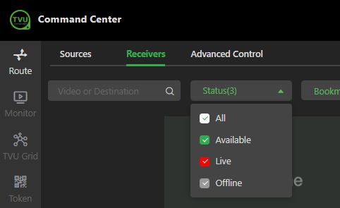
The receiver page includes the following Advanced and Status functions: (A) Status menu selections: Filters your receiver options.
Status selection descriptions are as follows:
All: Selecting the All checkbox automatically selects All of the status checkboxes.
Available: Selecting only the Available checkbox will display all receivers that are online AND idle, which means that they are not live with any source but are ready to do so. Offline and Live receivers are excluded from the results.
Live: Selecting only the Live checkbox will display receivers currently taking a source live. Online (idle) and offline receivers are excluded from the results.
Offline: Selecting only the Offline checkbox will only show offline and unusable receivers. Take (Live), and online (idle) receivers will be excluded from the results.
(B) Advanced icon: Opens the Advanced Control page. (C) Bookmark icon: Select the Bookmark icon to mark a source as a favorite and add it to your Bookmark list. Bookmark menu: Clicking the Bookmark menu and selecting Favorite will display Favorite sources a user has created.
Filter menu: Clicking the Sort by Name menu will arrange the displayed receivers by Online First, Live First, and By Name.
Taking a source live
There are three methods to take a source live:
From the Source page
From the Receivers page
From the Advanced Control page
To take a source live from the Source page:
Click the Route tab, then the Sources tab.
In the Sources page, filter your selections using the Type drop-down menu.
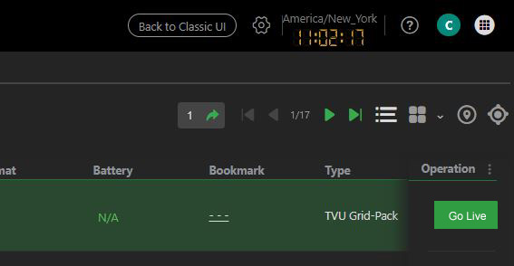
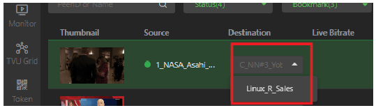
Select a source, then use the drop-down menu in the Destination column to pair the receiver.
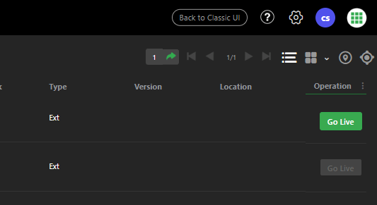
In the Operation column, click the green Go Live button.
To view the source, click the source name to expand the source window. To stop the source, click the red Stop button.
To take a source live from the Receivers page:
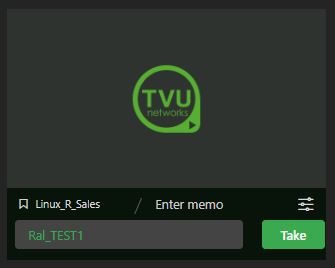
Click the Route tab and select the Receivers tab. In the Receiver page, enter a source name/PeerID in the source field or click the source field and make a selection from the drop-down menu to go live with.
Click the green Take button to go live.
The live transmission is displayed on the Receivers page.
To take a source live from the Advanced Control page:
Click the Route tab, then select the Advanced Control tab.
The Advanced Control page opens. Click the source field and select a source from the source menu. Click the green Take button to go live. The live transmission is displayed in the expanded Receiver Control window.
The live transmission audio is muted by default. To hear the live transmission audio, click the green Speaker icon in the lower right corner of the live stream preview window.
To stop the live transmission, click the red Stop button above the preview window.
Note: Exiting the Advanced Control page will not stop the live transmission.
If you exit from the Advanced Control page before stopping a live transmission, you can stop the transmission by clicking the red Stop button on the Receivers page.
Route tab – Receiver tab operations
Click the Route tab, then select the Receivers tab. Click the preview window on the Receiver page to expand the receiver panel.
The version information details and transmission status display.
Click the “i” icon to display the receiver PID and version information.
Route tab – Advanced Control tab operations
To open the Advanced Control page, click the Route tab, then select the Advanced Control tab. Users can also click the Advanced icon of a receiver block on the Receivers page.
The Advanced Control page opens.
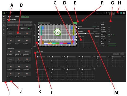
The Advanced Control page has the following indicators and advanced operations controls:
(A) Search bar: Use the Search bar to locate a PID or source Name. (B) Alert: The Alert tab supports TVU Analytics for full monitoring of data usage, including pre-set alerts for data usage thresholds using the Alert feature. (C) Setting menu: Mouse over the Setting icon to open a drop-down style menu that shows available configuration options for your selected receiver. (D) Source selection name (above the preview) and Source panel drop-down menus: Use the menus to select a source you want to go live with.
Note: Greyed out sources in the drop-down menu are offline and unavailable to use.
(E) Live, Record, and Transcriber tabs: These buttons control the content that displays below them. The live mode will show the individual modems for the transmitter and their current status. Record mode will show the console for managing recorded content on the selected transmitter. The Transcriber tab displays real-time speech to text transcribed content. This is a paid service and it becomes available when this feature is enabled.
Refer to “Live and record modes” for detailed information about recordings.
(F) Mute icon: Mouse over the live video preview to reveal a mute button in the lower-right corner of the video preview window. Click the green Speaker icon to enable or disable audio output to your PC. This button does not affect the audio output of the stream. (G) Live (Take) and Stop button: After you have selected a source from the drop-down menu, click the green Take (Live) button to start receiving that source. It will then become a red Stop button. Click the Stop button to stop receiving the source. (H) Delay and Bitrate settings: Use the Delay and Bitrate sliders to control the bitrate and delay settings of a TVU Pack stream. Bitrate and delay settings are only available for TVU Pack streams. Users do not have bitrate and delay setting sliders for Grid or External IP streams. The dynamic drop-down menu on the delay slider is specific to Grid only and determines whether you want to receive the stream at a fixed delay or use the dynamic delay that fluctuates in response to the Grid stream’s health. Using the dynamic delay for Grid is recommended. (I) Stream quality histogram: The stream quality histogram is a live-updating graph that displays the data throughput of the current transmission as the receiver receives it. Click the Setting drop-down menu above the histogram to change the scale of the graph. The setting option ranges from a maximum setting of 1.2 Mbp/s to 24 Mb/s. Clicking on the “quality” of the histogram opens a pop-up that allows for a searchable graph of the histogram. It is useful for looking into previous disruptions and can provide a clearer timestamp of any drops or transmission quality issues. (J) Receiver PID, version, and Time Remaining details: The Details panel displays the receiver’s PID and version. The Time Remaining indicator is above the Detail panel. (K) Setting icon: The setting icon in the top-right navigation offers options to change settings that affect other areas within Command Center. They include creating bookmark groups, adding external sources, adding user-level accounts, and locating individual hardware devices. (L) Source metrics: The source metrics represent the health and format of a source and its transmission. The Battery, error rate, and line quality will only populate for a TVU Pack transmission. The Video Input indicates if the pack’s input is SDI or HDMI. The Input format is the format of the source (not just for packs), and Output format is the SDI output video format of the receiver.
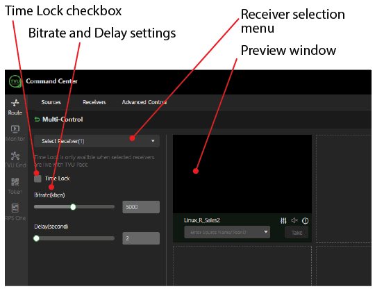
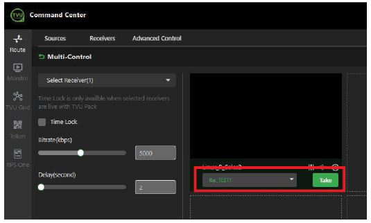
Receivers page -Using the Multi-Control button
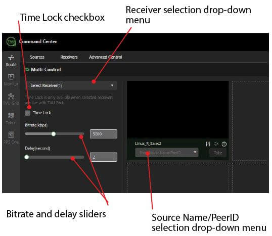
The Multi-Control dialog window allows the user to perform the following functions:
Select Receiver drop-down menu: Allows the user to select more than six receivers to control at once.
Time Lock: Time Lock is only available when all selected receivers are live with a TVU Pack. Activate this to synchronize all receivers in the window with the same bitrate and delay within two frames. This is useful for multi-camera productions of a common subject. If you receive an error, contact support to update your receivers to the correct version to support this feature.
Receiver block window: This function allows you to access receiver control windows. Any currently live video content will play in real-time in this receiver block.
Bitrate and delay sliders: Bitrate and delay sliders are only available when the Time Lock feature checkbox is active. The Time Lock feature changes bitrate and delay settings for all receivers in the window.
VoIP start button: Starts a VoIP call with a TVU Pack:
Click the VoIP start button (the green phone icon). Available TVU Packs to start a VoIP call, displayed in a small window.
Select the number of packs and click Start the call to begin communication from your local PC to the selected packs.
The call button will become red when a call is active. Click the red button to end the call.
To open the Multi-Control window:
Click the Route tab, then the Receivers tab in the top navigation panel.
Click the green Multi-Control button on the Receivers page.
The Multi-Control window displays.
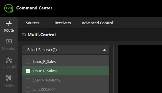
To add receivers to the Multi-Control window:
Click the Select Receiver drop-down menu.
Select the receiver checkboxes you want to add to your Multi-Control window.
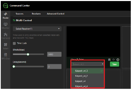
Enter a source name or click the Source drop-down menu below the preview window to select and go live with a source.
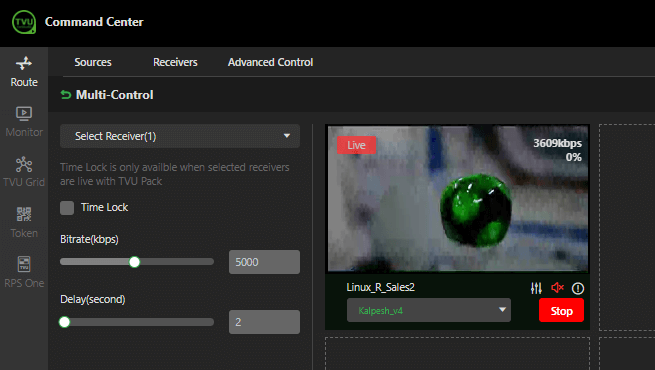
Click the green Take button.
To stop the live source, click the red Stop button.
Time Lock feature
The Time Lock feature is only available when all selected receivers are live with a TVU transmitter.
Click the Time Lock checkbox to synchronize all receivers in the window with the same bitrate and delay within two frames. This feature is helpful for multi-camera productions of a common subject. If you receive an error, contact support to update your receivers to the correct version to support this feature.
The bitrate and delay sliders are only available when the Time Lock checkbox is active. Use the sliders to change the bitrate and delay settings for all receivers in the window.
Multi-Control preview video controls and functions
Each receiver you select will display in the Multi-Control window as a separate block. The sources associated with your receiver selection are selectable using the Source selection drop-down menu.
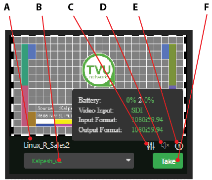
The Multi-control preview block has the following video controls and functions:
(A)Receiver: This field displays the selected receiver from the receivers page.
(B) Source selection drop-down menu: Click the drop-down menu to select a source to go live with. Then click the Take button.
(C)System settings: Click the SystemSettings icon to open the Receiver Web Controls user interface page in a new tab.
(D)Audio mute icon: Click the speaker icon to mute or unmute the audio. Note that this does not affect the video’s output audio.
E)Receiver information icon: The receiver’s information icon “I” displays the battery status, video input, input format, and output format information.
(F) Take/Stop button: Click the Take button to start the transmission. Click the Stop button to stop the transmission.
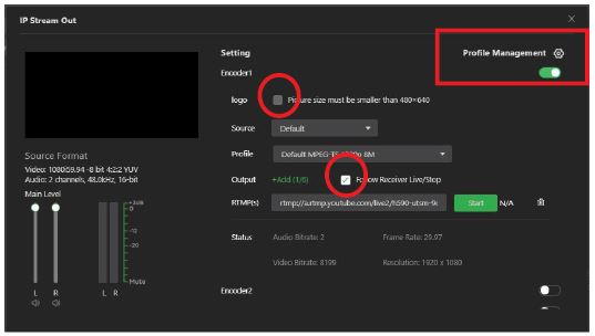
IP Streaming Output
Each encoder allows customers to configure six streams using the same stream profile.
To use the IP Streaming Output feature:
Click the Route tab, then select the Advanced Control tab in the top navigation panel.
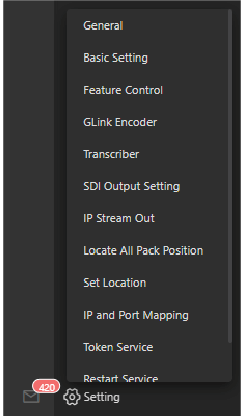
Hover the mouse over the Setting icon and select IP Streaming Out.
The IP Stream Out configuration screen displays.
Note: To Add or edit an IP Stream Out profile, click Profile Management.
Enable one or multiple Encoder sliders to activate up to six external IP streaming encoders. Each encoder sends one stream.
Click the Follow Receiver Live/Stop checkbox to choose whether you want the source to be the currently live source or take the receiver’s SDI input as the source.
To overlay a graphic logo onto your stream (PNG is the only accepted format), click the Logo checkbox and select a custom image.
Select a Profile from the drop-down menu.
To choose the stream you want to start and select the Output type. Multiple checkboxes can be selected.
When ready, enter your stream URL in the output field and click the green Start button to begin streaming.
You can adjust the Main Level audio bars to adjust the stream’s audio level relative to the source, or to mute audio on certain channels.
To stop the stream, click the red Stop button and close the window.
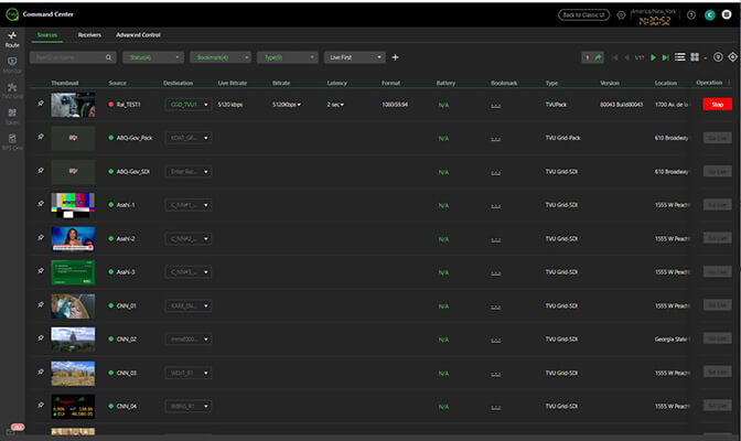
Route tab – Sources page
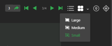
When you click the Route tab, the Sources page is selected by default. The Source Control page displays available source thumbnails in the list view. If desired, sources can also be viewed in large, medium, and small video preview blocks. These may include Grid, external, SMPTE2022, and YouTube sources. The Source Control page provides an extended view of your sources. The Status, Bookmark, Type, and Live First drop-down menus function as those on the Advanced Control page.
Sources page functions
The Sources page displays in list view by default and includes the following controls and functions:
(A)Search: Enter the source PID or Name in the search bar and press enter to locate a source.
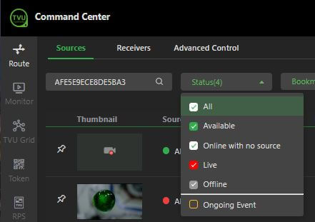
(B) Status: Click the Status drop-down menu to display sources based on the source types you select in the drop-down menu.
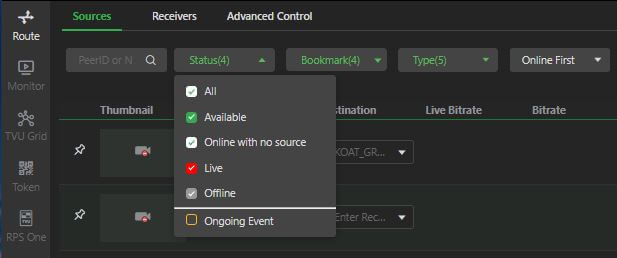
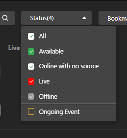
Status menu selection descriptions are as follows:
All: When you check the All checkbox, it automatically selects all options in the drop-down menu without checking them separately.
Available: When you check the Available checkbox, all available sources display.
Online with no source: Choosing only the Online with no source checkbox will display all online sources with no active video source connected to it. When checked, sources are not currently live with any receiver on your account but are ready to do so. The Offline and Live (Take) sources are excluded from the results.
Live: Choosing only the Live checkbox will display receivers currently taking a source live. Online (idle) and offline receivers are excluded from the results.
Offline: Choosing only the Offline checkbox will show receivers that are offline and unusable. Take (Live), and online (idle) receivers will be excluded from the results.
Ongoing event: Display events that are always live.
Note: Status menu checkbox color indicators are: Green = Online (Idle), Red = Live (Take), Grey = Offline
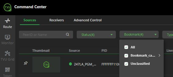
(C) Bookmark: The Bookmark drop-down menu allows a user to define specific arrangements of sources to display.
There is one difference between the bookmark drop-down menu on the Sources page and the Receivers page; the Sources bookmark drop-down menu includes a default group called Token. Using the bookmark checkbox (with the All and Unclassified boxes unchecked) will display only those sources added using the Token tool. These will typically be mobile devices using the TVU Anywhere app.
Alternative arrangements of sources can be displayed using the Bookmark drop-down menu. The user creates these by utilizing the Bookmark tool in the Settings menu.
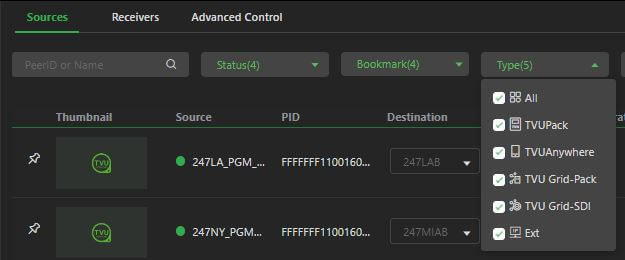
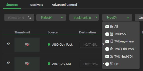
(D) Type: Click the Type drop-down menu to display your sources based on type. The results displayed below the drop-down menu correspond to the selected checkboxes.
Type menu selection descriptions are as follows:
All: Displays All source types.
TVU Pack: Displays TVU hardware transmitters.
TVU Anywhere: Displays mobile devices using the TVU Anywhere app.
Grid-Pack: Displays a re-encode of a partner’s TVU Pack or TVU Anywhere transmission from their receiver.
Grid-SDI: Displays an encode of a partner’s in-house content fed to their receiver’s SDI input.
Ext: Displays external IP sources, such as YouTube or IP cameras.
Grid via Token: Displays Grid sources that have been added to your account temporarily by the Token service.
Global Grid: Displays Grid sources only made available by participating in Global Grid.
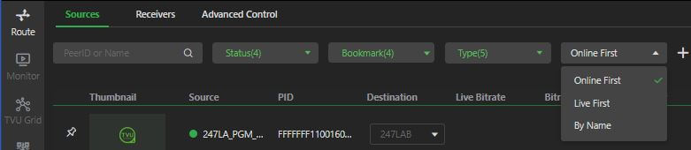
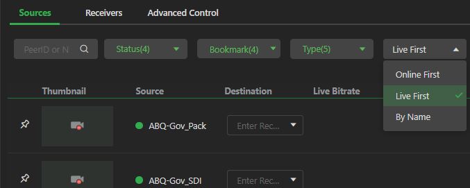
(E) Source filter: Click the Source filter drop-down to filter, select, and display the following source views:
Online first: Displays sources that are online (idle) and online with no source first. Live first: Displays sources that are currently live with a receiver first. By name: Displays source results in alphabetical order.
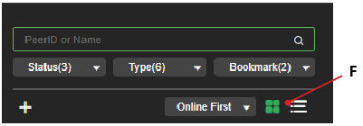
(F) Add external source: Click the plus “+” icon to add an external source to the sources panel.
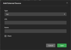
Adding an external source
The plus “+” icon enables users to add an external source, such as a YouTube video or an IP camera. The added source displays in the source panel with the other source thumbnails.
To add a new external source:
Click the Route tab, then the plus “+” icon in the Source Control window to add an external source to the sources panel.
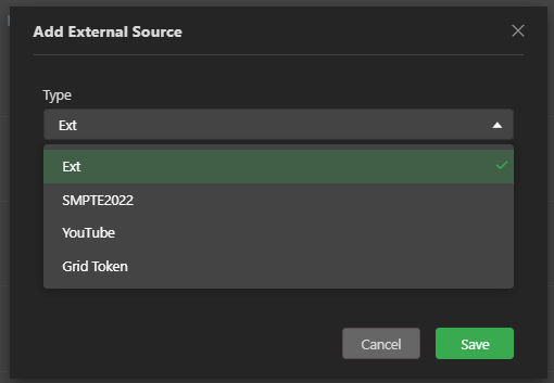
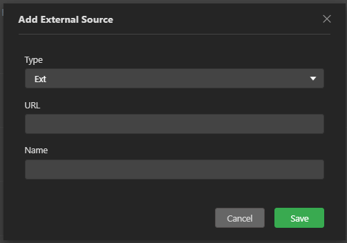
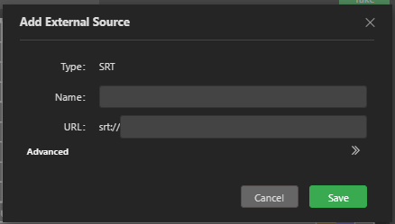
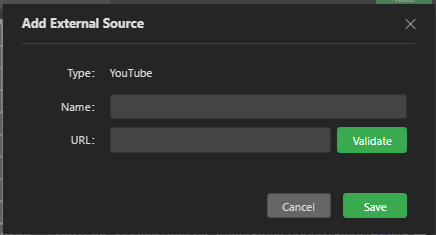
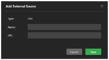
The Add External Source window opens.
Open the Type drop-down menu and make a selection.
Enter the source URL.
Enter a Name or description of the source. Then, click Save.
(G) Page navigation: Click these buttons to flip through multiple pages of sources, go to a specific page, or skip to the last page.
(H) Source view options: These two icons let you switch between thumbnail and list views. The thumbnail view is the default and shows all of your results with a periodically updating preview window of the source’s content, the source name, and a status indicator showing whether it is online, live, or offline.
By default, sources are displayed in list view with thumbnail previews, along with the source name and status, these previews update periodically.
To locate a source or change the source views:
Click the List view icon to view your sources in a list view.
To view your sources by source thumbnail, click the Thumbnail icon.
To locate a source’s physical location, click the Geo-location icon.
(I)Geo location icon: Click the Pin icon to open a geographic map with pins showing the physical location of all available sources and receivers.
Click the Route tab, then the Receiver selection drop-down menu, and select a receiver.
Click the Go Live button in the Operation column.
To stop the transmission, click the Stop button.
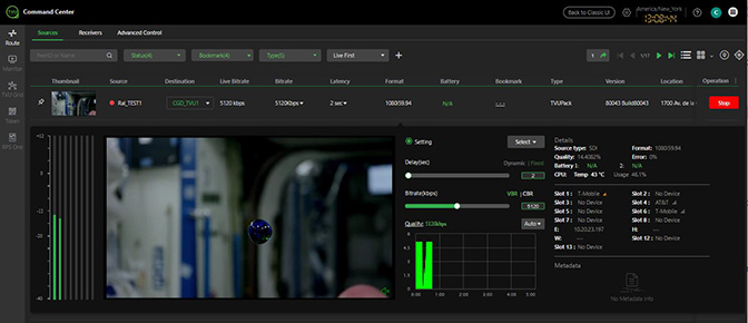
Expanded Source Control panel
The sources behave differently than the Expanded view on the Receivers page. When you click a source thumbnail on the Sources page, an expanded view of the source and a settings panel is displayed, as shown below.
Note: The following image is taken from the Sources page, which has the settings gear that opens a Pack source’s WEB UI. The gear does not show for grid sources or in the Receivers tab.
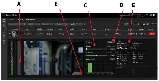
The expanded source pop-up window includes the following controls and functions:
(A) Audio levels: This view displays up to 8 audio levels.
(B)Mute icon: Click the speaker icon to mute the audio output to Command Center. This will not affect the actual audio output of the source to your receiver.
(C)Control settings: Delay and bitrate settings.
(D)Select button: Click the Select drop-down menu to change the pack’s bitrate and delay settings using preset modes. TVU provides five preset modes: Interview, Normal, Fast, Moving, SD (Standard Definition), and Tape Feed.
(E)Details panel: Source (input) type, format, (line) quality, error rate, and battery life of the pack are displayed in the Details panel. A new IP address section will display the IP address of your Ethernet and WiFi interfaces. Finally, a new section for metadata about the transmission is available.
Route tab – Receivers tab
The Receivers page offers a similar experience to the Sources page, except that each thumbnail represents a receiver instead of a source. Thumbnails on this page only show video when that receiver is live with a source, and that video is presented as a periodically updated frame. The Receivers tab offers a view that allows simultaneous control over multiple receivers (receivers) simultaneously.
To open the Receivers page, select the Route tab, then click the Receivers tab in the top navigation panel.
Receivers page controls and functions
The Receivers page offers a view that allows simultaneous control over multiple receivers. This page also includes the following checkboxes for controls and functions located in the main navigation:
(A)Search: Enter the source Video or Destination in the search bar and press Enter to locate a source.
(B)Status menu: The status drop-down menu includes a series of checkboxes. The All, Live, Available, and Offline checkboxes will function the same as in the other tabs.
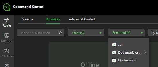
(C) Bookmark menu: A new Favorite checkbox can be added to this menu along with All and Unclassified.
Note: the bookmark menu is hidden from new users and users who have not previously set up a bookmark category. Refer to “To create a Bookmark category” for more information.
(D) By Name: If you select this menu, results will be shown in the order of Live first, Online First, and By Name.
(E) Multi-Control button: Opens the Multi-Control window.
(F) Page navigation: Click the navigation buttons to browse through multiple pages of sources, go to a specific page, or skip to the last page.
(G) Page views: Large, medium, or small thumbnail views.
Receiver block controls
Receiver block controls: The receiver thumbnail will have elements that should already be familiar to you, such as the receiver name, source selection drop-down, and the Take (Live) button. A new addition to the source thumbnail block is the Enter Memo text box and the Bookmark icon. Click the Bookmark icon to Add to or Add a new bookmark.
The source block controls and functions (when idle) are described as follows:
(A) Receiver name: Your selected receiver name displays in this field. (B) Memo text box: The user can enter custom information about the receiver thumbnail in the memo text box. Click the memo box to activate the text cursor. Then, customize the thumbnail description. (C) Source selection drop-down menu: Click the source field to open the drop-down menu and select a source to go live with. (D) Advanced icon: Click the Advanced icon to open the Advanced Control page. This icon can appear when live.
The source block controls and functions (when Live) are described as follows:
(A) Source status indicator: The Source indicator displays “Live” when the source is live.
(B) Receiver name: Your selected receiver name displays in this field.
(C) Source selection drop-down menu: Click the Source field to open the drop-down menu and select a source to go live with.
(D) Click the Expand info icon to open the source settings status overlay. (E) VoIP icon: Starts a VoIP call with a TVU Pack. (F) Publish icon: Click the publish icon to publish your output video stream to a website type of your choice.
(G) Expanded receiver panel: Click the source preview thumbnail to open the expanded version of the receiver thumbnail. In this view, you will see live moving video. You will also have a mute button in the bottom-right corner of the expanded live video window. The control panel allows you to adjust bitrate, delay, VBR/CBR, and dynamic or fixed delay.
Click the “i” icon to open the receiver status panel.
Going live with a source
To go live with a source from the Receivers page:
Click the Receiver thumbnail block. The expanded information displays below the thumbnail, similar to the Sources page.
Click the Source drop-down menu in the Receiver thumbnail block and select a source. Then, click the Take button to go live with that source. Click the preview block to open the expanded receiver view to monitor the live transmission.
Click the thumbnail again to close the window.
Publishing a video stream to social media
You can publish your video stream to a social media site when your transmitter source is live on the Receivers page. To set up a social media source refer to “Social Account tab.”
To publish your source to a social media site:
Click the Publish icon.
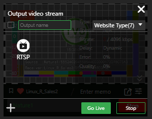
The Output Video Stream overlay is displayed.
Click +Add at the bottom of the window.
Select a social media name or Other output from the drop-down menu.
In the pop-up window, enter the required information for your selection.
Make a selection from the Website Type drop-down menu.
Click the Go Live button to publish.
To stop your video stream, click the Stop button, then click the X to close the window.
Advanced Control page
To select a receiver:
Click the Route tab, then the Receivers tab in the top navigation panel.
Click on an available receiver name to display source results corresponding to your receiver selection as source thumbnails.
Users can access the Advanced Control page from the Receivers page by clicking the Advanced icon in a source block or by clicking the Advanced Control tab.
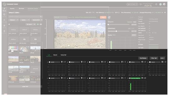
The Advanced Control page displays the selected receiver and its sources, along with any available sources associated with that receiver. The Advanced Control page includes the following six main control panels:
The Advanced Control page includes the following controls and functions:
(A)Search bar: Search for a source name or PeerID
(B)Source panel thumbnails: This section contains all available sources for the selected receiver along with filtering and search options.
(C)Live, Record, and Transcriber tabs: These tabs control the content that is displayed below them. Live mode will show the individual modems for the transmitter and their current status. Record mode will show the console for managing recorded content on the selected transmitter. When Transcriber is enabled, operators can use the real-time speech-to-text transcribing service.
(D)Live preview and Take/Stop button: This section contains the live preview window and a drop-down menu for selecting a source to take live. The Take / Stop button, used for starting and stopping a transmission, is also located here.
(E)Control panel: This section contains options for editing the bitrate and delay of a transmission as well as data related to the current status of the transmission such as, quality, error rate, video format, and IFB / VoIP status. You can also find the receiver PID in this section.
(F)Setting gear: Mouse over the setting gear to expand a drop-down menu that shows available configuration options for your selected receiver.
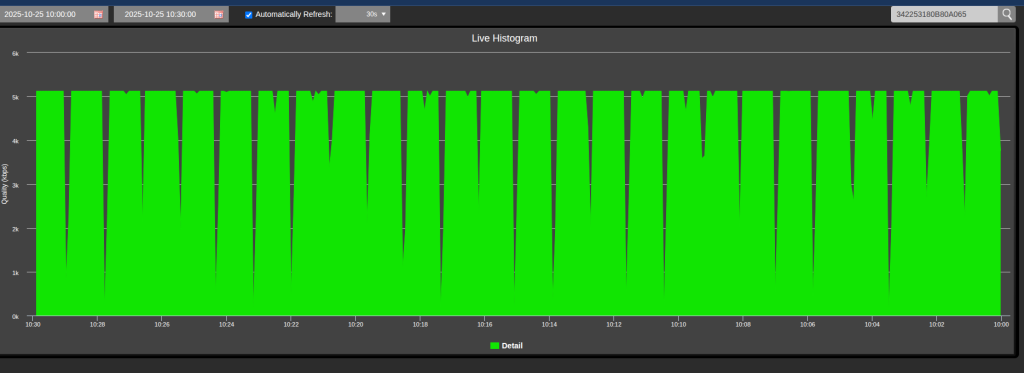
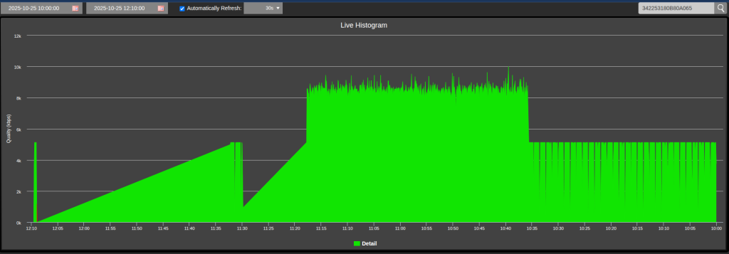
(G) Quality histogram: Clicking the “quality” of the histogram opens a pop-up that lets you search the histogram. It is useful for investigating previous disruptions and can provide clearer timestamps for any drops or transmission quality issues.
There are drop-down calendars to select the beginning date and time, and the ending date and time. The default time frame for bringing into view is 30 minutes; this can be adjusted to up to 4 hours. The search can go back in time about 5 days.
(H) Modem monitoring and status: This panel displays the transmitter’s modem histograms and current status.
Selecting a source
Click the Route tab, then click the Advanced Control tab in the top navigation panel.
The source selection panel is located in the left panel of the Advanced Control page.
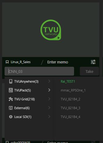
The Source panel menu displays TVU Pack, TVU Grid, G-Link, Local SDI, TVU Anywhere, and External sources.
To select a source:
In the source panel, click on the desired live source thumbnail.
After the source is selected, a red box will frame the thumbnail image.
Note: Selecting a transmitter that has a video preview will start a live session.
The source is displayed in the preview window. If the live source was previously activated and then stopped, the thumbnail will continue to display, framed in red. To take the source live again, click the Live button.
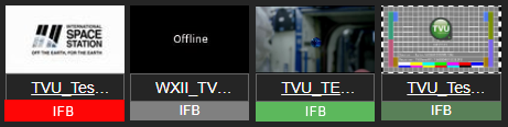
Source status indicators
The source thumbnails will display using one of the following status indicators:
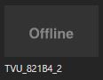
This thumbnail indicates that the video source is offline.
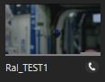
This thumbnail indicates that the remote source is powered and connected, but no video input is detected.
This thumbnail indicates that the video source is online and live video is detected.
This thumbnail indicates that the video is a generic external source. Other available external sources include SMPTE, YouTube, and SRT, each with its respective thumbnail icon.
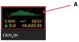
(A)Source video feed thumbnail: When a source is selected and live, the thumbnail is framed with a red box around the thumbnail image.
This thumbnail indicates that the video source is selected and taken live.
(B)Source information: Mouse over the thumbnail to display the source information. When a transmitter is online, its name will appear below the thumbnail.
(C)Search bar: The operator can search for available input sources by name.
(D)IFB indicator (VoIP predecessor): The Interruptible Feedback (IFB) feature used in older model transmitters allows your news operations center to speak directly to a TVU transmitter in the field. The IFB option includes a mixer/preamp. The mixer has a USB port for connecting to your receiver and an XLR and 1/4 in. port for plugging in a microphone.
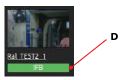
IFB: To turn on IFB, click “IFB” below the thumbnail. When IFB is on, the background color turns red.
To turn off IFB, click “IFB” below the thumbnail. When IFB is off, the background color turns green.
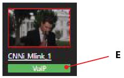
(E)VoIP indicator: The VoIP function provides a two-way, higher-quality communication than IFB. Click the VoIP (phone icon) under the live preview to use VoIP. When enabled, the VoIP background color turns from green to flashing red to solid red. VoIP is enabled automatically when a live transmission starts.
The VoIP/IFB status also displays in the diagnostics “Status” panel on the left side of the interface.
Additionally, if a TVU transmitter has a VoIP or IFB function, only IFB will automatically become enabled when going live.
(F) View by thumbnail or list: These features allow the operator to display all of the TVU transmitters and their status in a graphic thumbnail or in a list.
Located below the search field in the Source panel are three drop-down menus: the Status, Type, and Bookmark menu. These menus have the following functions:
(G) Click the Status drop-down menu below the “Search” bar to select and display any source by Live, Online, or Offline status.
(H) Click the Type drop-down menu below the “Search” bar to select and display any source by type.
(I) After creating a bookmark category, the Bookmark menu will be displayed. An operator can also choose source types to display by their status by clicking the Bookmark drop-down menu below the “Search” bar.
(J) An operator can also filter displayed source types by their status by clicking the Filter drop-down menu below the “Search” bar.
(K) In addition, an operator can click the Plus “+” to choose an external source. Generic External, SMPTE, YouTube, G-Link, SRT, NDI, and Zixi are available external sources.
Taking a shot live
To take the shot live, open the Advanced Control page and complete the following steps:
Click the thumbnail in the source panel to start a live session with a source not already framed with a red box.
Click the Live button to start a live session with a source framed with a red box.
Set the bitrate, delay, and VBR/CBR settings.
Setting the variable bitrate (VBR) and delay
The two primary controls that affect the quality and latency of a live shot are the bitrate and delay sliders.
To set or edit the bitrate and delay, complete the following steps:
Delay: To configure the live shot latency, manually adjust the slider or enter a value in the input box (the maximum delay is 50 seconds by default) and press Enter.
This value is always stable and will not change during the transmission unless it is manually adjusted. Delays as low as 0.5 seconds should be routinely achievable in good bandwidth conditions. Lower delays are related to the amount of bandwidth consumed for error correction, so higher delays of 4 to 10 seconds are recommended for non-latency-sensitive transmissions.
Bitrate: Use the slider to select a value, or enter it manually into the input box and press Enter.
A higher value will increase the encoding quality and transmission throughput of the pack (subject to bandwidth availability) to a maximum threshold of 10 Mbps. Bitrates above 5 Mbps should not be required except for fast or high-motion videos, such as sports videos.
Note: The encoding bitrate can be increased for certain specialized applications. Contact Support for details. Changes to the bitrate slider can be made during a live transmission without interrupting the shot.
Note: Adjusting the Delay setting during a live transmission will interrupt the video while the stream rebuffers.
Click the Select drop-down menu to view user-definable presets. Depending on your news-gathering environment, you can define the following preset bitrates and latencies:
Note: Presets can be adjusted. Contact support for more information.
User 1 & User 2: These are user-definable presets. To program them, users right-click the preset they want to define. They can then name the preset, change the bitrate, manually set latency, or check Set Current, saving the current latency setting to that preset. Once finished, they Press Apply to the program.
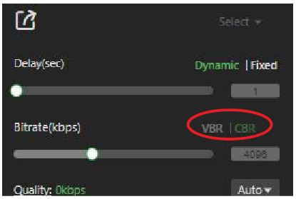
Selecting VBR vs. CBR
The TVU system uses SmartVBR™ adaptive encoding technology to maximize the reliability of the live transmission. The encoder detects the available bandwidth and adjusts the encoding bitrate up to the maximum value set on the slider. If the SmartVBR detects a drop in available bandwidth, it will decrease the encoding resolution to keep the video stable and smooth.
Variable bitrate (VBR) mode
VBR is the default setting and should be used under most circumstances. Click the VBR drop-down menu above the bitrate slider to select or change the setting.
Constant bitrate (CBR) mode
In some circumstances, turning off the VBR logic and forcing the transmission to CBR mode may be desirable. The encoding will be locked to the configured CBR mode bitrate regardless of available bandwidth. The most common application for this setting is with IP satellite systems with fixed bandwidth.
Tuning a shot
In a live interactive environment with ample bandwidth, the normal operation would combine a high bitrate with a low delay for a smooth, stable transmission. If the bandwidth is constrained and the transmission is not stable at the configured settings, the operator has two primary controls to affect the transmission:
Increase the delay of the transmission. An increase in delay reduces the error-correction overhead required for stability. A reduction in overhead frees up more available bandwidth for video quality. The delay can be increased from 0.5-second steps up to 10 seconds.
A stepped increase of 0.5 seconds to a maximum of 10 seconds should be attempted.
If the transmission is especially delay-sensitive or the conditions are very challenging, bitrate reductions should be performed in steps of approximately 500 Kbps until stability is achieved.
Combining these two controls should allow the operator to routinely and reliably manage video streams from challenging environments.
Note: When transmitting a very low movement or still setting, the pack will adjust and use less data until movement is reintroduced. This is normal behavior.
IFB indicator feature
The Interruptible Feedback (IFB) feature (used with early model transmitters) allows your news operations center to speak directly to a TVU transmitter in the field without needing telephone contact. The IFB option includes a mixer/preamp. The mixer has a USB port for connecting to your receiver, an XLR, and 1/4-inch ports for plugging in a microphone.
On the TVU transmitter, connect a standard set of headphones to the 3.5 mm audio jack on the unit.
To use the IFB feature, click the IFB indicator until it turns red. The IFB on/off status is also indicated in the “Status” panel on the right side of the interface. Additionally, if a TVU transmitter has an IFB function, the IFB is automatically turned on when that transmitter goes live. Once the live transmission is stopped, the IFB function is turned off.
The five indicator colors displayed in “IFB indicators” are defined as follows:
Red: The IFB function is in use.
Green: The IFB function is available but not in use.
Green-Gray: Either the transmitter is live with another receiver or using the IFB function with another receiver.
Gray: The IFB Function is not available for this transmitter.
VoIP indicator feature
VoIP indicator: The VoIP function provides a two-way, higher-quality communication than IFB. Click the VoIP indicator under the live preview to enable VoIP. When enabled, the VoIP background color turns from green to flashing red to solid red. VoIP is automatically enabled when starting a live transmission and disabled manually by pressing the button.
Note: For VS3500/VS3550 hardware models, an external audio box is required to support XLR audio input/output.
Note: The VoIP/IFB status also displays in the diagnostics “Status” panel on the right side of the interface.
Additionally, if a TVU transmitter has a VoIP or IFB function, both IFB and VoIP will automatically become enabled when going live.
Using the IS+ feature
IS+ is an advanced version of TVU Networks’ Inverse StatMux technology. With superior forward error correction technology, IS+ also has a higher throughput than the standard Inverse StatMux under the same conditions. Additionally, with IS+, file transfers are between 2x and 4x faster than standard Inverse StatMux. This solution enables TVU transmitters to deliver resilient, HD, professional broadcast-quality pictures in even the most challenging wireless environments.
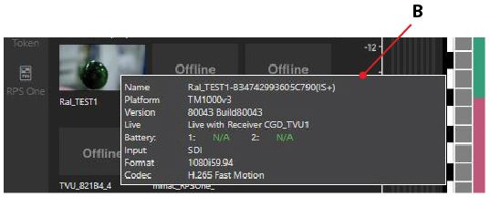
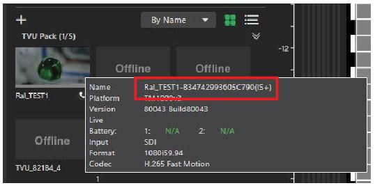
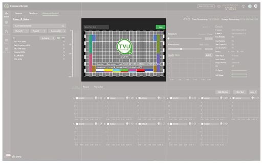
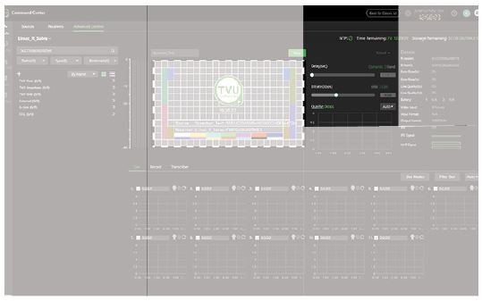
Once IS+ has been installed on a TVU transmitter, “(IS+)” will appear at the end of the PID when you mouse over the source thumbnail, as shown in “IS+ location” below.
TVU Grid source
To view the available Grid sources, click the Status menu and select a status. Click the Type drop-down menu and select Grid-pack.
Adding an external source
To add an external source to the receiver Web UI, complete the following steps:
Click the plus “+” icon next to the Status drop-down menu. The external source pop-up window displays.
Select an external source from the pop-up window to be added. The supported formats are:
Generic External Source
SMPTE2022 Source
YouTube Source
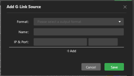
G-Link Source
SRT Source
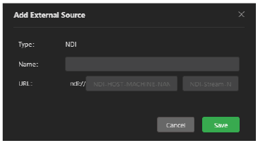
NDI Source
Zixi Source
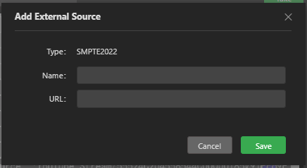
A pop-up window displays each external selection. Enter a Type and the appropriate information as follows:
When finished, click Save. A thumbnail icon of the added source will display as a selection in the source menu.
Data transmission monitor panel
The data transmission monitor panel is located below the preview panel.
The data transmission monitor panel includes visual modem histograms with the following controls and functions:
(A)Data transmission monitor panel (Live tab): This panel displays all data connections’ current number and status. The connection status appears as green, red, yellow, or gray.
(B)Check box: There is a check box and status bar associated with each card. The check box enables or disables a data connection. If unchecked, it will not be used to pass data. If the box is checked (default), the connection will be used to pass data.
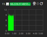
(C)Monitor histogram: Displays status, throughput, and the IP address of each modem.
(D)Connection mode and connection strength indicator: The connection mode is displayed next to the connection strength, indicated with three bars.
(E) Configuration menu: This modem configuration icon connects to the pack’s WEB UI.
(F)Reset: This feature provides a full-power reset for a modem. It is used when the modem can no longer connect or is experiencing a problem. Click the Reset icon to force the modem to power cycle and reset.
(G) Connection name and status: Individual read-out panels show each active card’s carrier name (when available). The slot number of each datacard is indicated in front of the carrier name. To retrieve the IP Address of a datacard, mouse over the name of that datacard. You can enter your preferred name if a name is not automatically provided and displayed. However, this will reset upon reboot.
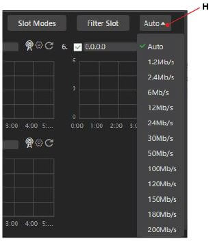
(H)Scale: The Scale drop-down menu allows the operator to set the scale for the histogram. When the scale is changed, it will affect all of the histograms displayed. Selection settings are 1.2 Mbps, 2.4 Mbps, 6 Mbps, 12 Mbps, 24 Mbps, 30 Mbps, 50 Mbps, 100 Mbps, 120 Mbps, 150 Mbps, 180 Mbps, and 200 Mbps.
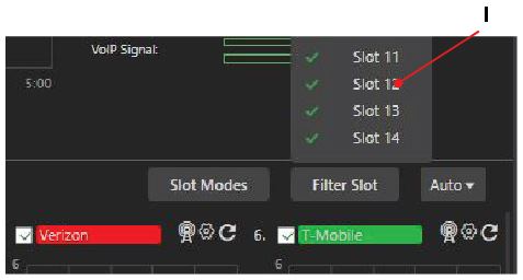
(I) Filter Slot: Use the Filter Slot menu to select which slots you want to display in the data transmission panel.
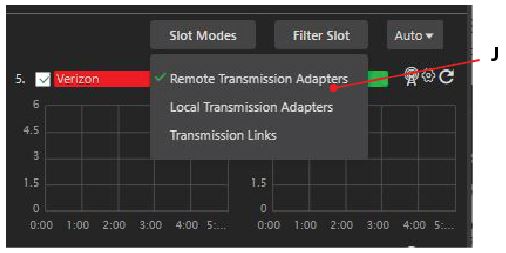
(J) Slot Modes: Use the Slot Modes drop-down menu to select a Transmission type for your slots.
(K)Mode selection tabs: The data transmission panel has up to three mode selection tabs:
Live: The Live mode is the primary interface used during a Live transmission. When this tab is selected, the status of each of the data card network connections will be displayed.
Record: The Record mode displays the store and forward interface to preview, download, and manage TVU Transmitter stored footage and files transferred via Auto Sync. This interface can also access files transferred via FTP.
Transcriber: The Transcriber tab also displays if the Transcriber feature is enabled. When enabled, the speech-to-text transcription is displayed.
Live and record modes are located in the data transmission panel.
The Live and Record tabs control the content displayed for each histogram. The live mode will show the individual modems for the transmitter and their current status. Record mode will show the console for managing recorded content on the selected transmitter.
The Live, Record, and Transcriber tabs for the data transmission monitor panel are shown below.
In the Live tab, the checkboxes for each data connection status bar enable or disable that connection. The box is enabled (checked) by default.
Click the check box to select and use the data connection. If the box is unchecked, the card will not pass data.
Note: When a datacard is installed, the carrier name and the slot number displays next to the check box.
To change the scale of the modem histogram, click the Auto drop-down menu at the top right to display the value menu. Then, click to select a desired maximum value.
Note: Changing the value will affect all modem histograms.
To retrieve the IP address of a data card, hover over the data card field name.
If there appears to be no name associated with the card, you can enter your name, which is displayed as <name>.
Note: The name change will reset itself upon a reboot.
The color indicators displayed within the carrier name panel indicate the following status:
Red: Not connected but dialing
Green: Connected and passing traffic
Yellow: Connected but not passing traffic
Gray: Disconnected or unplugged
Manual modem configuration
To manually configure a transmitter’s modems, complete the following steps:
In the source panel, click the desired source thumbnail. When selected, the source is framed with a red box.
To configure the modem, click the Setting “gear” icon above the source histogram.
The System Status page opens in a new window. Click the Modem icon.
The Modems panel opens. Select the Auto radio button. To save your configuration changes, click Apply.
The modem configuration on the pack is accessible in the modem option in the drop-down menu.
To manually select which carrier a modem will roam on:
Enable the Roaming slider.
Click the Manual radio button at the bottom of the Modem configuration screen.
Click the Scan button. The roaming modem will automatically generate a list of available carriers.
Click to select a desired Carrier, then click Apply to confirm your selection.
Setting menu
The Setting “gear” icon is located in the bottom-left corner of the Advanced Controls page. Click the Setting icon to open the Advanced setting menu and select your available settings.
The controls and functions in this menu are as follows:
The video preview window shows the live video output state or the offline state screens. The preview window has audio control capability. When a video is live, the operator can mute or unmute the audio to the live video by clicking the speaker icon in the bottom right corner of the preview window.
Note: The audio button only affects the audio output to your Web browser. It does not affect the SDI output to your receiver.
When a source is live, the video preview displays in the preview window, and the red Stop button displays. To stop the transmission, click the red Stop button.
When a source is not live, the video preview displays the following TVU slate, and the green Take button displays.
Take/Stop button: The Take/Stop button allows the operator to stop or restart a live transmission from a selected source.
Setting panel controls
The setting panel Delay, Bitrate, Adaptive Delay, and VBR/CBR controls are located below.
The setting panel includes the following controls and functions:
(A)Delay control: Set your desired latency and then the maximum bitrate you would like to utilize. When in “Live” mode, the error rate and picture quality will automatically adjust based on the desired latency and available bandwidth to produce the highest-quality picture.
(B)Bitrate control: The TVU receiver has a smart VBR scaling system. This means the unit will automatically adjust the bitrate to deliver the best-quality picture based on the desired latency. To effectively take advantage of the smart VBR scaling system, set your desired latency, then set the maximum bitrate you would like to use.
(C) Adaptive delay control (Dynamic/fixed) for Grid only: Controls the dynamic buffering feature of Grid. When set to dynamic mode (recommended), the receiver will automatically increase the stream buffer to ensure stable transmission. This selection maximizes stream stability, but at the potential cost of increasing the delay/latency. The Fixed mode will lock the Grid stream to a specific delay, but will allow errors if the setting is too aggressive. It is recommended that dynamic mode be used as usual. When fixed mode is enabled, the operator should pay extra attention to stream stability with their current settings.
(D)VBR/CBR: The TVU receiver has a smart VBR scaling system.
(E) Preset selection menu (operational): Click the Select drop-down menu to view user-definable presets.
Note: Presets can be adjusted, contact support for more information.
Status panel diagnostics
The Status panel has many vertical indicators to help an operator make quality and troubleshooting decisions. Additional information, such as error rate, line quality, and a histogram showing the total transmission encoding bitrate over a period. The histogram’s scale can be changed by selecting a different display option from the drop-down menu. The status of the transmitter’s batteries is also displayed.
The Status panel and histogram locations are shown below.
The Status panel includes the following controls and functions:
(A)Input and output formats: “Input” displays the video input format of the transmitter. “Output” displays the receiver output setting.
Note: The receiver output format follows the input format. When the Input Match feature within Feature Control is enabled.
The TVU Pack input and receiver output should match. The receiver software is not intended to convert or adjust the resolution. In the event of a mismatch, the receiver will attempt a format conversion, but this may result in a loss of video quality and the removal of closed captions from the transmission.
(B)IFB status: The IFB status and the IFB Signal visually display. The IFB signal has a strength meter that depicts the input level of the IFB.
(C)VoIP status: The VoIP Signal has a strength meter that depicts the input level.
(D) Quality histogram/Quality link: The quality histogram below the Quality link displays a 5-minute aggregate histogram of the live transmission.
Settings page
The Settings “gear” icon in the top-right navigation offers options to change settings that affect other areas within Command Center. They include creating bookmark groups, adding external sources, adding user-level accounts, and locating individual hardware devices.
There are nine tabs in the top navigation on the Settings page. The first tab that is opened by default when clicking the setting icon is the Preferences tab.
The Setting page has the following features and controls:
(A)Preference: The Preference tab allows users to enable notification confirmations for starting and stopping a live transmission and to show Geo-location over thumbnails.
(B) Device: The Device tab in the Setting window allows a user to view available paired receivers and source data and the option to rename a device.
To use the Device tab functions, complete the following steps:
Click the Device tab. The Device window displays.
To locate a specific device, enter the PID or Name in the search bar and press Enter.
To display Bookmarked devices, click the Bookmark drop-down menu and make a selection.
To display a device by type, click the Type drop-down menu and make a selection.
To display a device by location, click the Location drop-down menu.
To rename a device, click Edit in the right column, rename the device, and click Save.
(C)Account: The Account tab in the Setting window allows you (the administrative account holder) to create a Co-Admin or user-level account for your colleagues. It is highly recommended that you do this, as the administrator account has unrestricted power over all devices and sources in your Command Center. You can set restrictions such as going live and stopping live, accessing specific receivers and sources, and accessing other features. TVU discourages sharing the administrator account credentials with others.
To modify or create a new Sub-level user account with an SSO login, refer to “Setting up a Sub-User level account SSO login method”. To modify an existing user who prefers an SSO login, refer to Steps 5 and 6.
Creating a new user or Co-admin role
Account owners can create a new user-level role or a Co-admin role.
Please use real e-mail addresses. Refer to the account creation window below for access customization.
To create a user-level account, complete the following steps:
Click the Account tab > Plus icon “+.”
The User Creation window is displayed.
Enter a valid email address, First and Last name, Password, Role, and select the corresponding checkbox permissions.
Click Save.
After you create an account, the new account email displays in the account tab list.
Click an email address in the list. The Relation Management window opens. Note that User name and status fields are displayed at the top of the window.
In the Available Device column, enter the receiver PID into the search field.
Select the device(s) you would like your user to have access to and click the Add or Add All button to move your selection(s) into the Binding Device column.
Click the Save button when finished.
Account tab – Download the template and import accounts
The account tab enables users to download a template and import accounts. To download a template, click the Download Template icon located above the Operation column.
To Import accounts, click the Import Accounts icon, then follow the prompts.
New role modifications
To modify, deactivate, or delete a new sub-user role:
To modify a new role, click the Account tab. Click the Modify Permission, Deactivate, or Delete in the Operation column.
Click the email address in the Account tab to open the Relation Management window to modify pairings.
Click Save when finished.
Setting up a Sub-User level account SSO login method
When the Administrative account holder creates a new user-level account, and the user prefers using an SSO login, there is no need to set a TVU password. An optional SSO login method can be configured.
To configure a Sub-user level SSO login:
Click the Setting icon > Account tab and click the Plus “+” icon.
The User Creation window is displayed.
Enter the new user’s email, first and last name, and Role.
Select the SSO checkbox, the desired Permissions, and click Save.
To Modify an existing user-level account for SSO login, locate the user in the Account list and click the Modify Permission link.
The Modify Permission window is displayed. Select the SSO checkbox and click Save.
(D)External source: The External source tab in the Settings window allows users to add external sources such as YouTube, EXT, and SMPTE2022 sources to their source list.
To create an external source, Click the External Source tab.
Enter your receiver’s PID or Name in the search field. Then, click the plus “+” icon. The Add External Source window opens.
Select the Type of source from the Type drop-down menu.
Enter the URL if required and enter a Name, then click Save.
The external source is displayed in the External Source list.
(E)Operation log: The Operation Log tab lists a user’s Command Center activity. The activity can be filtered by date, operation type, and email.
(F)Bookmark: The Bookmark tab in the Setting window allows a user to create and share bookmarks for devices and sources (also referred to as category bookmarks) that are configured in the Relation Management window. The device and source groups you create are available in the bookmark menus on other Command Center tabs.
For example, you could create and share a group of receivers and sources that are meant only for a particular team with a Command Center account within your organization.
To add a device to a bookmark
To create a bookmark category and add a device to the bookmark:
Click the Bookmark tab.
Hover over My Bookmark. Click the plus “+” icon to create a new bookmark category. The Create Bookmark window will then display.
In the Create Bookmark pop-up window, enter a Bookmark name and click Save.
Select your bookmark name from the bookmark panel to add a device to your bookmark, then click the Add Device button.
The Relation Management window opens. Note that the selected bookmark name is displayed at the top of the Relation Management window.
Enter the Available device PID or Name in the search field. The Available Device column displays a list of available devices. You can also filter your devices by clicking the Filter drop-down menu.
Select an available device name to add to the Binding device column. Click the Add or Add All button to move the device(s) to the Binding Device column.
Click Save to save your entries.
Your bound device displays in the Bookmark list.
Select a device in the bound device list to Duplicate to another device, Move, Remove devices from the bookmark, or Add another device to a bookmark.
(G)Social Account: The Social Account tab allows users to quickly and easily transmit to a supported CDN such as Facebook and YouTube. Only receivers that are currently live with a source display in the Live Video screen.
There are two sharing methods available:
Use the Publish button on a live receiver’s thumbnail using a saved Social Media account in the Social Account tab.
Use the Facebook Share Directly button on one of your live receiver thumbnails.
The Social Account tab has the following features and controls:
Live video sources
To enable the Video preview functions:
To share with other CDNs besides Facebook, add your social media account, click the Social Account tab and the plus “+” icon, and follow the instructions.
After you add your account, return to the Live Video preview and click the Publish button on the thumbnail of the receiver you would like to share.
Select the account you want to use and click the Share button to begin sharing.
Click the Stop button to stop sharing.
Social Account tab
To share with Facebook, complete the following steps:
Add your Facebook account via the Social Account tab, then use the Facebook Share Directly button on the live receiver thumbnail you want to share.
Click the Authenticate radio button. The Output Setting window opens.
Add your desired details. Then, click Go Live to start sharing.
To stop sharing, click the Publish button on the receiver’s thumbnail and click Stop.
(H)Access APP: The Access App tab functionality allows users to set up an API access app by company name.
To set up an API Access App:
Click the Access App tab.
Enter a Company Name in the field to verify any existing accounts.
Click the plus “+” icon in the Access App tab. The Create an Access window opens.
Enter the company name and select the activation method radio buttons.
Click the Save button.
(I)Licensed Feature Report: The Licensed Feature Report tab allows a user to filter and view Command Center licensed features by device, Account, Role, and Owner email address.
To use the Command Center Licensed Feature Report, complete the following steps:
Click the Licenced Feature Report tab. The Licensed Feature Report window displays.
Use the Drop-down menu to select Command Center tab access.
Click the calendar icons to select a date range. Then, click the Filter button.
To review an activation time by account, click the account name in the list.
The Account activation setting window opens.
When finished, click Ok.
Monitor tab
The Monitor tab allows users to watch a full-motion video of their receivers that are currently live. Users can listen to the output audio, full-screen individual windows, and use VoIP controls to communicate with each receiver’s respective TVU Pack.
The Multi-view tab includes the following controls and functions:
(A)Receiver selection drop-down: Clicking here will open a menu of available live receivers By Chosen order, By Name, or By Status to add to the multi-view windows. There is also the option to add a bookmark group of receivers from the Bookmark drop-down menu. To create and display your own Bookmarks, set them up in the Settings > Bookmark tab.
(B) VoIP start button: Clicking the VoIP start button (the green phone icon) opens a small window displaying available TVU Packs to start a VoIP call. Select the number of packs and click “Start the call” to begin communication from your local PC to the selected packs. The call button will become red when a call is active. Click the red button to end the call.
(C)View selections: You can increase the number of available windows by selecting one of these viewing option icons. There is a maximum of 25 windows. A full-screen button is also present that will collapse the Command Center navigation bar when selected.
(D)Audio meter, Show Info, and Page Never Times Out sliders: Enable the Audio meter to listen to audio and Show Info slider to show the preview transmission details. Enable the Page Never Times Out slider to monitor live transmissions without timing out.
Grid tab
The new TVU Grid for Command Center features form part of a three-tiered service that allows TVU Command Center account owners to access and manage Grid sources outside of their traditional organizational boundaries. This new Grid service uses the expanded Command Center user interface to search for, request, and go live with these sources.
Token is a feature accessible within the TVU Command Center User Interface. The TVU Anywhere app integrates with the token feature, which allows an operator to perform automatic receiver pairing without the intervention of TVU Support.
To use the TVU Anywhere token feature, it requires a token license activation from TVU Support.
The Advanced Control page Settings drop-down menu in the bottom-left of the Advanced Control page displays the following General and Basic configuration setting selections:
General
The General setting window allows users to:
Select a time zone.
Enable Custom NTP service. When enabled, the Time Lock feature will become disabled.
Configure the microphone and speaker devices.
Enable VoIP to start with live.
Enable a prompt warning when stopping a live transmission.
When using the Progressive download feature, choose to auto-convert recorded streams to MOV, MXF, and MP4 formats.
Enable a default for delay and bitrate settings.
Configure the Eternal source buffer size.
Choose a Video Feedback resolution and rate.
Enable Switch Live on Hold to Standby.
Basic setting – Network IP and port mapping
To review the Network IP and port mapping settings, click the Settings gear and select Basic Setting. The TVU Networks Setup page displays.
The TVU Network Setup page has the following controls.
The TVU Network Setup page contains the following configurable panels:
(A) Home button – Opens the TVU WebR page
(B) Network settings
(C) DNS settings
(D) Web Control – Displays PIDs
(E) System settings – Restart Service, Factory Reset, Restart System, Update firmware, and Shut Down controls.
Click the Home button in the top right corner of the interface to access links from the Receiver interface page.
The Receiver interface page includes the following links:
Web Control Network Setup File Browser Migration Port Test Security Update (beta) Service Control
Refer to the “TVU Server Hardware Setup User Guide, Models VS3100, VS3200, VS3250, VS3500, and VS3500 – Linux” for hardware set up and configuration instructions.
Feature Control
Many features in the Feature Control menu must be enabled before they can be used. To access the Feature Control menu and enable features, complete the following steps:
Click the Route tab and Advanced Control tab.
From the Receivers page, click the Advanced icon.
To open the Feature Control settings dialog, click the Settings gear in the bottom-left panel and select Feature Control.
The Feature Control dialog displays.
Move the slider to the right to enable a feature, or move the slider to the left to disable a feature.
Restart the receiver software for changes to take place.
Feature Control settings are as follows. These features may be enabled or disabled in the Feature Control window:
Auto Download: Enable the Auto Download feature if you want a live session to download automatically after the session stops.
Auto Live Resume: This feature automatically resumes the last live source when the receiver shuts down.
Auto Record: When Auto Record is enabled, live transmissions from the receiver are recorded to local storage.
Auto Sync: Auto Sync is a high-speed file transfer feature that automatically pushes the files from the transmitter to the receiver using ISX.
There are two Auto Sync methods you can use to send files to the TVU receiver automatically:
You can perform Auto Sync by inserting a USB stick into the transmitter.
You can use the TVU transmitter wireless hotspot feature to transfer files directly to the TVU transmitter for upload.
Booking Service: TVU Booking Service is a simple scheduling solution designed to help broadcasters better manage multiple streams within their IP video workflow within the Grid ecosystem.
External Source Receiving: When enabled, this feature allows the operator to connect to external video sources, including YouTube, by using an IP address or URL.
Global Grid: TVU Grid’s web-based, easy-to-use interface grants control over all TVU servers by request.
IP Streaming Output: The live video transmission is encoded into an IP format and can be sent to six remote locations.
Input match: The receiver SDI output will be converted to match the source input resolution setting.
Live Encoder Support: The Live Encoder support controls one function.
Enabling the operation of the Command Center Share function when used in conjunction with a social media account.
Local SDI: The operator can view SDI input as a local source.
Remote File Storage: Use the Remote File Storage to push downloaded files to external FTP receivers.
SDI to IP: Enables an SDI input for IP streaming output.
TVU G-Link Encoder: The TVU G-Link encoder feature slider enables the G-Link encoder on the transceiver.
TVUG-Link Receiving: The G-Link decoder feature enables the TVU transceiver to receive the encoding of a G-Link enabled TVU transceiver.
TVU Transcriber: TVU Transcriber is a real-time speech-to-text transcribing service. For detailed information, refer to the TVU Transcriber Feature Guide.
TVUGrid Encoder: Enable the encoding of a TVU pack or local SDI stream to Grid.
TVUGrid Receiving: Set to receive Grid feeds.
TVUMe Receiving: TVUMe allows news organizations to connect with video content providers and freelancers worldwide to exchange live and recorded content.
TVU Pack Receiving: Enable TVU Pack Receiving to allow the encoding of the pack stream or local SDI stream to Grid.
Time Lock: The Time Lock feature enables multiple TVU One’s to synchronize with other receivers at the same set latency.
Token Service: The Token Service allows users to create and share Grid and TVU Anywhere Tokens.
Video Feedback: This option enables the remote video feedback function, encoding content at the receiver and sending it to field equipment for remote monitoring.
Vision Tag: Used to enable/disable live MediaMind AI facial and location recognition.
Web File Support: Enables ENPS integration functions.
Grid Encoder
To view the Grid Encoder feature, ensure the feature is enabled in the Feature Control window. Then, complete the following steps:
Click the Settings menu and select Grid Encoder.
The Grid Encoder dialog window displays.
Click the Source drop-down menu to select which source type you want available on output 1.
Note: Output 2 will always use the SDI input as its source.
When finished, close the window.
G-Link Encoder
TVU G-Link encoder feature slider enables the G-Link encoder on the transceiver. G-Link Encoder allows users to configure their video’s bitrate so that G-Link can select a codec.
To configure the GLink source, open the Settings menu and select GLink Encoder.
The GLink Encoder window opens.
In the Output 1 panel, select a source from the Source drop-down menu.
Make a CODEC selection.
Set the Bitrate and enter a Port number.
In the Output 2 panel, select a CODEC.
Set the Bitrate and enter a Port number.
SDI Output settings
SDI settings can be configured for single or dual-output receivers. To access the SDI Output settings dialog, click Settings and select SDI Output Setting.
The SDI Output Setting window opens.
SDI Output settings overview:
On: Enable SDI Output. Card ID: When enabled, use the Card ID drop-down to select either 1 or 2 for the SDI output.
Note: If the card ID is set to 1, then the video output will be the center BNC connector. If the card ID is set to 2, then the video output will be the far right connector.
Refer to “Dual output receiver configurations”.
Output Format: Use the Output format drop-down menu to select a resolution for your video output.
3G-SDI formats: Choose a format. Select SMPTE Level A or SMPTE Level B from the drop-down menu.
Custom logo: To add a logo to your SDI output, check the Custom logo checkbox, enter the X and Y offset positions, click the Plus “+” to add a logo, and follow the prompts.
Aspect: Select an aspect ratio from the drop-down menu.
Last Frame: Select Logo from the Last Frame drop-down to output the TVU slate screen. Select Last Frame to repeat the last frame or select Black for no image.
Last Frame lasts for N seconds: Enter a value for the “Last Frame” selection to display.
Audio Channels: Use the Audio Channels drop-down to select 2, 8, or 16 audio channels.
Output -12 db audio while standing by (checkbox): Click the check box to enable a 12 dB audio output along with the TVU slate. When the box is unchecked, the 12 dB audio output is disabled, and the TVU slate is only enabled.
Stay on the last frame during transmission interruption (checkbox): Click this checkbox to enable the “Last Frame” and “Last Frame to last for N seconds” settings in the event of a transmission interruption.
Note: In the event of any changes made to the SDI Output setting dialog, you are prompted to restart the receiver for settings to take effect.
Dual-output receiver configurations
With a dual-receiver configuration, an operator can access each receiver by completing the following steps:
Click the Web Control drop-down menu and select a receiver from the list.
Log in to the TVU receiver UI.
IP and Port Mapping
The IP and Port Mapping setting enables users to add a receiver IP and configure the port mapping.
To configure a receiver IP, click the Settings menu and select IP and Port Mapping.
The IP and Port Mapping window opens.
Click +Add to add a Receiver IP to Slot 2.
Fill in the appropriate fields and click Apply.
Token Service
The Token Service allows users to create and share Grid and TVU Anywhere sources that they own by creating Tokens.
To Create Tokens:
Open the Settings menu and select Token Service.
The Token Service page displays.
Click the Create a new Token tab and enter a Receiver Name and Receiver ID.
Click the Get IP button to obtain the Receiver IP.
Enter the Receiver Time Span.
To add a second receiver, Click the Plus “+” button, and enter the IP address and Time Span in the provided fields.
Enter the Receiver Email, Transmitter Name, Transmitter PID, and Transmitter Email.
Click the Create button.
In the Set a Token tab, Enter the Token information and click the Set Token button.
Auto Download feature
To enable the Auto Download feature, complete the following steps from the Advanced Control page:
Open the Settings menu and select Feature Control.
The Feature Control settings menu displays.
To enable this feature, drag the Auto Download slider to the right until it turns green.
Click the Apply and Restart Now button.
Close the Feature Control window and refresh the screen.
To ensure that Auto download has been enabled, open the Settings menu. The Auto download displays as a selection. Click Auto download.
The Auto Download pop-up dialog displays.
Enable Auto Download and close the pop-up window.
Progressive Download feature
If the TVU receiver is available, the TVU transmitter can automatically trigger the immediate upload of a mirror image of a high-resolution clip from its SSD to the TVU receiver by pressing the camcorder’s record button. The TVU receiver will display the download process.
To use the Progressive Download feature, complete the following steps from the Advanced Control tab:
To access the Progressive Download dialog, open the Settings menu and select General.
The General pop-up dialog displays.
In the Progressive Download panel, click the Auto-Convert to drop-down menu to select from three conversion options for the mirror image.
When finished, click Apply and click the X to close the window.
Locate All Pack Positions
Locate All pack positions dialog displays the location of all live TVU Packs using GPS.
To view pack positions, open the Settings menu and select Locate All Pack Positions.
The GPS location window opens.
Use your mouse to hover over the location pin to display the TVU Packs’ PID.
Notes:
In order to improve the location accuracy, make sure the TVU Pack is connected to a WiFi card.
If there is no real-time GPS data for a TVU transmitter, cache GPS data will be used for that TVU transmitter, and the location pin displays red.
Source GPS locations, tracking, and previews
From the Source Control window, in the top-right navigation panel, the geographic location of the transmitted video and tracking information are available.
To locate the physical location of a source, click the geo-location pin icon.
To Track a device by mode, click the Tracking icon. The Tracking window opens. Select a Tracking mode.
["TVU Home Quick Start User Guide","TVU RPS Link Encoder Model TE5700 Hardware Setup Guide","TVU RPS Link Encoder v6.7 Software Setup Guide","TVU RPS VS3500 Hardware Setup Guide","TVU RPS VS3500 Software User Guide","TVU Servers Linux v8.4 Hardware User Guide","TVU Servers Linux v8.4 Software User Guide","TVU RPSVS3600 Multi-Channel Software User Guide v8.1","TVU Command Center User Guide","TVU Remote Commentator Quick Start Guide","TVU Partyline Quick Start User Guide","TVU Anywhere Quick Start Guide","TVU Producer Quick Start User Guide","TVU Producer Advanced Audio Mixer User Guide","TVU MLink TE5500 v7.4 and TE5800 v8.0 User Guide","TVU RPS One Model TM1100 Software QSUG v8.3","TVU One Model TM1000v4 Software QSUG v8.3","TVU RPS One Model TM1100 Hardware QSUG v8.3","TVU One Model TM1000v4 Hardware QSUG v8.3","TVU One TM1000v3 FHD and 4K Hardware Quick Start User Guide","TVU RPS One Model TM1100 Software QSUG v8.2","TVU MediaHub Quick Start User Guide","TVU Home User Guide (Beta) version","TVU Review Quick Start User Guide","TVU Replay Quick Start User Guide","TVU Servers Linux v8.3 Software User Guide","TVU Servers Linux v8.3 Hardware User Guide","TVU Router Portal Quick Start User Guide","TVU Media Analyzer Quick Start User Guide","TVU One TM1000v3 FHD and 4K Software Quick Start User Guide","TVU MLink TE5500 and TE5700 User Guide v7.4","TVU Anywhere Lite Fast Track Guide","TVU POWERPAC and POWERPAC 2 Quick Start User Guide","TVU Servers Linux v8.2 Software User Guide","The One Model TM1100 Software Quick Start User Guide","TVU Servers Linux v8.2 Hardware User Guide","TVU Timelock Quick Start User Guide","TVU One Model TM1100 HDMI RVF Quick Start User Guide","The One Model TM1100 Hardware Quick Start User Guide","TVU Producer Advanced Audio Mixer User Guide","TVU Servers Linux v8.1 Software User Guide","TVU Servers Linux v8.1 Hardware User Guide","The One Model TM1100 Software User Guide","TVU Nano Router (5G) Model RD300 Setup and User Guide","TVU Rack Router 5G Hardware Setup and User Guide","TVU MLink TE5500 and TE5700 User Guide","TVU G-Link Software feature User Guide","How to configure TVU Channel settings tutorial","TVU Servers Linux v7.9 Hardware User Guide","TVU Servers Linux v7.9 Software User Guide","How to add an HLS output in TVU Channel","How to add an ISSP output in TVU Channel","How to add an SRT output in TVU Channel","How to go live with HLS to VLC in TVU Channel","How to show, hide, create, and delete folders in TVU Channel","How to add an RTMP output in TVU Channel","How to add a UDP output in TVU Channel","How to add an RTSP output in TVU Channel","How to add a Facebook output in TVU Channel","How to add a Yi Live output in TVU Channel","How to add a Twitter output in TVU Channel","How to add a Twitch output in TVU Channel","How to add a KuaiShou output in TVU Channel","How to output a Generic IP stream in TVU Channel","How to use the emergency switch function in TVU Channel","How to use TVU Transcriber\/CC in TVU Channel","How to configure TVU Channel Settings in Workbench","How to use keyboard shortcuts in TVU Channel","How to create a new channel in TVU Channel","How to change TVU Channel Settings in Workbench","TVU Channel User Guide","TVU Servers Linux v7.8 Software User Guide","TVU One Li-ion Battery Safety and Use Guidelines","TVU Grid for Command Center Quick Start User Guide","TVU Command Center File-Based Workflows User Guide","TVU Grid Token Quick Start User Guide","TVU Anywhere Token Quick Start User Guide","TVU Servers Linux v7.8 Hardware User Guide","TVU Search Quick Start User Guide","TVU Transcriber Feature Guide","TVU POWERPAC Quick Start User Guide","How to tag participants in TVU Partyline","Where to learn about TVU Partyline updates and latest features","How to use the vertical video feature in TVU Producer","How to add video transitions in TVU Producer","How to use voice over IP (VoIP) with the TVU Anywhere app","How to use token pairing with TVU Anywhere","How to use TVU One Wired Remote Control","How to output to IP destinations in TVU Search","How to post a clip to Social Media in TVU Search","How to select templates when sharing clips in TVU Search","How to upload a facial image to find content in TVU Search","How to use facial selection to find the speech in TVU Search","How to select text to create a clip in TVU Search","How to create Grid tokens to share Grid feeds in TVU Command Center","How to use the Talkback feature in TVU Remote Commentator","How to add Singular Live graphic overlays in TVU Channel","How to add a Zixi output in TVU Channel","How to add a ProMPEG output in TVU Channel","How to add a YouTube output in TVU Channel","How to manage your program Schedule in TVU Channel","How to upload and verify media in TVU Channel","How to add and schedule live sources in TVU Channel","How to create a Program Template with SCTE markers in TVU Channel","How to delete and duplicate a program or media in TVU Channel","How to use the program settings window TVU Channel","How to move or drag and drop media into the TVU Channel Scheduler","How to create a Program Template in TVU Channel","How to create a Schedule Template in TVU Channel","How to change a live input source or program duration in TVU Channel","How to remove and replace live programs in the TVU Channel Playout window","How to add backgrounds and logos in TVU Partyline Kiosk mode","TVU Remote Commentator – How it works","How to use the Coordinator room in TVU Remote Commentator","How to use the commentator view in TVU Remote Commentator","How to invite commentators to join an event in TVU Remote Commentator","How to add commentary groups to an existing event in TVU Remote Commentator","How to change the backup input source in TVU Remote Commentator","How to switch to a backup feed in TVU Remote Commentator","How to set up a backup source in TVU Remote Commentator","How to create an event in TVU Remote Commentator","How to use the change layout function in TVU Partyline","How to use screen sharing as a host in TVU Partyline","How to use the Kiosk mode in TVU Partyline","How to use screen sharing as a participant in TVU Partyline","How to ingest IP video sources into TVU Producer","How to configure participant settings in TVU Partyline","How to add a Local video source in TVU Producer","How to add a Partyline feed in TVU Producer","How to use the clip recording feature in TVU Producer","How to add HTML video sources into TVU Producer","How to set up IFB and VoIP on a TVU receiver","How to use the “Take Next” feature","How to take your channel to Air","How to add and execute crawls","How to add a graphic logo overlay","How to break into and rejoin programming","How to build live and recorded program templates","How to schedule a program","How to duplicate\/repeat programs and program templates","How to create a Channel","How to add pre-recorded programs","How to add SCTE triggers to your program schedule","How to create and add schedule templates","How schedule live events","How to import and export the Programming Guide","How to enable Closed Captioning (CC)","How to use the TVU Command Center mobile App. For iOS","How to start TVU Partyline as a host","How to use Split Screen or Picture-by-Picture (PBP) with TVU Anywhere app.","How to integrate a Singular Live and graphic URL into TVU Producer","How to use the overlay feature in TVU Producer","How to use the pull or push feature with RTMP sources in TVU Producer","How to use Return Video Feedback (VFB) with the new TVU Anywhere user interface.","How to use replay in live productions with TVU Producer","How to use TVU Partyline for remote collaboration and conferencing for live video production","How to add a custom Dual and Quad-view video effect in TVU Producer","How to use TVU One Progressive Download mode","How to extend the battery life of a TVU One using the TVU POWERPAC Li-ion external battery.","How to conduct port tests with Linux v7.5 and 7.6 receiver software","How to use the Picture-in-Picture feature in TVU Producer","How to use the Picture-in-Picture (PiP) in TVU Partyline","How to use Picture-in-Picture (PIP) to play recorded video into the live stream, with the new TVU Anywhere user interface.","How to output multiple audio channels in TVU Producer","How to use the monitoring panel in TVU Producer.","How to lock and rename participants in TVU Partyline","How to join TVU Partyline as a participant","What is ISO Recording? Does TVU Producer support it?","How to use the group and private chat feature in TVU Partyline","How to use the full-screen feature in TVU Partyline","How to enable VLAN Service with the Linux v7.5,7.6 receiver software","How to add multiple custom views and borders in TVU Producer","How to use the remote collaboration feature in TVU Producer","How to use the clear overlay and remove overlay features in TVU Producer","How to add graphic overlays in TVU Producer","How to add a Grid source into TVU Producer","How to add a TVU One source into TVU Producer","How to add a TVU Anywhere app source into TVU Producer","How to add paired TVU Anywhere sources in TVU Producer","How to use the TVU One 4-Channel Encoder"]