Contents
- Introduction, setup, and base operation
- Key features
- Log in to the RPS Web interface
- Encoder controls and functions
- Accessing the TVU RPS Web interface using Command Center
- Configuring the encoder and decoder
- Establishing an Internet connection
- VLAN and VoIP configuration
- NTP configuration
- Output video format
- TVU RPS decoder server settings
- Transmitting to TVU Producer
- Encode Channel Monitor operations and settings
- RPS 4-channel Web interface overview
- Monitor client feature
- Product specifications
- Applications overview
TVU RPS Software User Guide

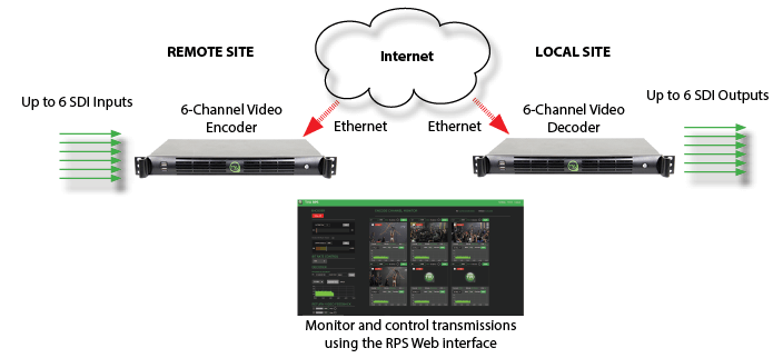
The TVU multi-channel RPS is a remote solution for at-home production/REMI (Remote Integration Model) production. TVU offers the only cost-effective RPS solution for frame-accurate, synchronized, multi-channel production over the public internet in the broadcast industry. Capture content live from any remote location and produce it instantly from your studio.
Chapter 1 – Introduction, setup, and base operation
TVU Remote Production System (RPS) is a cost-effective way to deliver live multi-camera broadcast using only a standard Internet connection and existing staff, equipment, and control room infrastructure.
With the TVU Remote Production System and TVU Timelock, you can produce professional quality video from up to six channels from the comfort of your facility, regardless of your network connection or whether your cameras are fixed or on the move.
Product overview
The TVU Remote Production System provides synchronized live multi-camera remote production. TVU RPS allows broadcasters to leverage their existing studio control room staff and equipment while using a public internet connection from the field. The TVU RPS provides a cost-effective alternative to live multi-camera remote coverage or production.
The TVU RPS transmitter encodes up to six synchronized SDI sources. It transmits high-quality, low-latency IP video from the remote location to a studio-based TVU RPS receiver, which outputs six synchronized SDI outputs. The TVU RPS can also send up to 2 low-latency return video feeds from the studio back to the field.
The TVU RPS encoder and decoder share the same basic hardware platform. The front panel features a simple button to power on the unit.
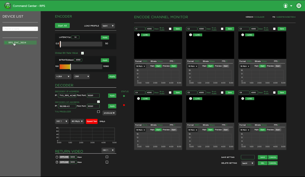
After the unit is set up and powered on, the TVU RPS Web interface, hosted on the encoder, monitors and controls the system.
You will use the TVU RPS Web interface to monitor and control all aspects of transmission, including real-time previews of all four channels with the Duo 2 card and all six channels with the Quad 2 card, current bitrate, and latency.
Key features
- Supports TVU Switch via VLAN Tunnel (Layer 2 connectivity). Users can now switch between standard VLAN tunnel and TVU Switch based VLAN tunnel.
- Transmit to RPS decoder and Producer simultaneously.
- Support for VBR and VBR Channel Priority transmitting to Producer or multiple decoders.
- Support for CC708/608 embedded captions transmission.
- Supports up to six fully synchronized multi-channel transmissions. Supports the 6-channel Quad 2 and 4-channel Duo 2 cards.
- Dependable, fixed, low-latency transmission over standard-contended Internet connections.
- Includes multiple encode behaviors to suit virtually any network environment.
- The RPS sends metadata and control from the studio to the field using a VLAN Tunnel.
- Support for return feeds and up to 16 channels of audio per SDI input.
- Compatible with TVU Producer 3.0, our cloud-based video production solution, to manage remote broadcasts from any location.
- A high-quality, low-latency video feed of the live program from the station via HDMI. Up to two low-latency return video feeds sent from the studio back to the field.
- The Monitor client feature sends an individual decoder output stream to a transceiver using an EXT IP source input with the ISSP protocol. In addition, decoder output streams can also be sent to an SRT decoder using the SRT protocol.
- The RPS encoder easy-to-use browser interface that is accessible using the TVU RPS Web interface or your TVU Command Center account.
- Supports the restart option for users.
About this guide
This user guide will enable you to:
- Set up the TVU RPS VS3500 encoder and decoder
- Log in to the RPS interface
- Configure the TVU RPS VS3500 encoder and decoder using the RPS Web interface.
- Operate the TVU RPS VS3500 encoder and decoder
Before you begin
Complete the following procedures in the TVU RPS Hardware Setup Guide to set up the TVU RPS VS3500 transmitter (encoder) and VS3500 receiver (decoder) hardware.
Logging in to the TVU RPS Web interface
To log in to the TVU RPS Web interface, have your encoder static IP address available and complete the following steps:
Log in to the RPS Web interface
- Open a Web browser window and enter:
http://IP_Address/rps/index.html
(Where IP_Address is your Encoder static IP address)
- Click Enter. The login pop-up displays.
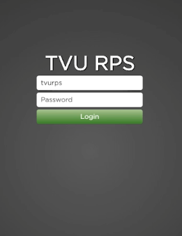
- To Log in to the RPS Web interface, Enter the following using all lowercase letters:
User ID: tvurps
Password: Enter the last 8-digits of the PID using all caps
- Click Login. The TVU RPS Web interface displays.
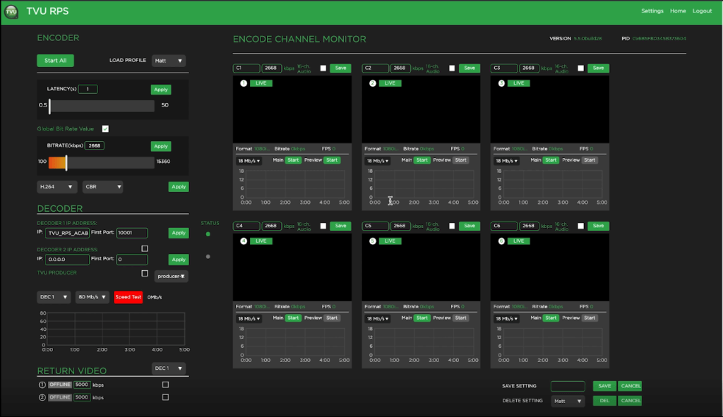
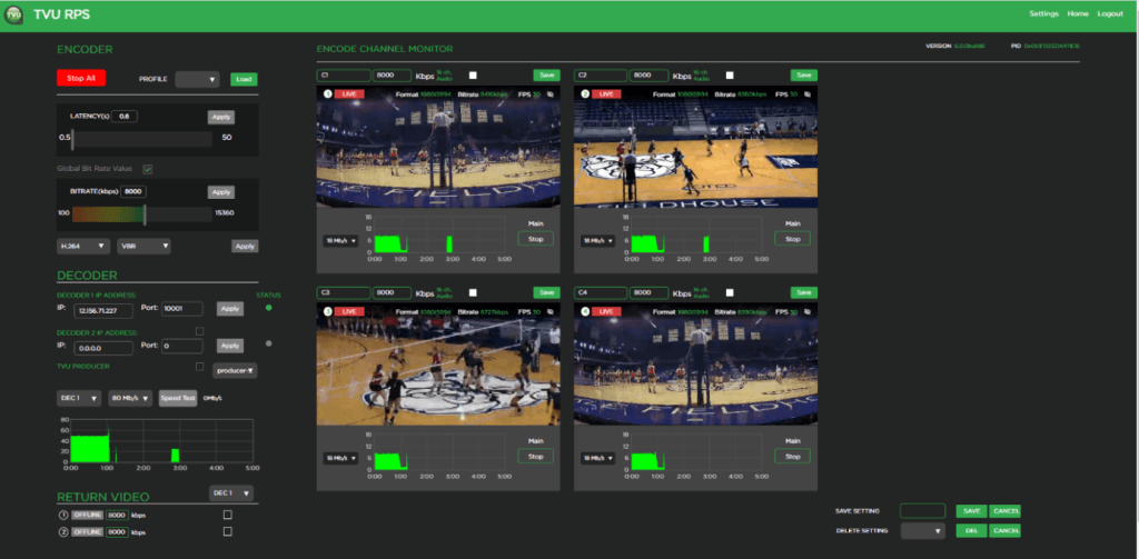
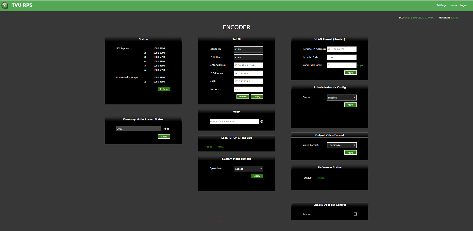
TVU RPS Web interface
The RPS Web interface has the following features and functions:

RPS 4-channel Duo 2 PCI Express card
The Duo 2 PCI Express, capture and playback card, features 4 independent 3G-SDI connections. The card supports SDI formats in SD and HD up to 1080p60 with the flexibility of 4 separate capture or playback cards in one.
Encoder controls and functions
(1) The Encoder panel
(2) The Encode Channel Monitor panel
(3) Settings menu – The Settings tab/menu
(4) The Return Video panel
(5) The Decoder panel
(6) Bitrate controls
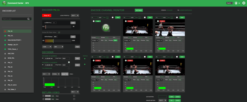
Accessing the TVU RPS Web interface using Command Center
The RPS user interface can be added to your Command Center account and accessed from within Command Center. With the Command Center interface, a user can control transmission virtually anywhere.
To access the TVU RPS Web interface using Command Center, complete the following steps:
- Log in to Command Center, click the services navigation icon, and select RPS.
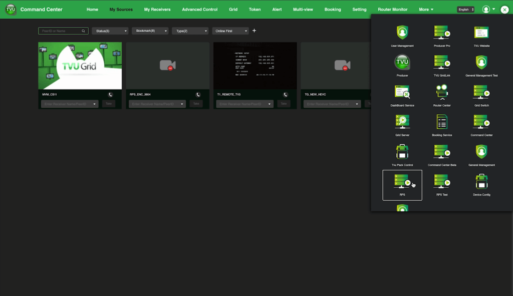
The Command Center RPS page displays.
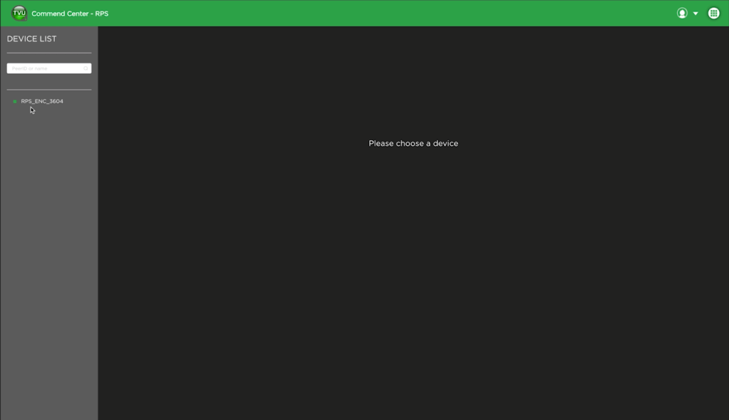
- Select the encoder you want to control in the Device list. The Command Center RPS Web interface displays.
Note: The RPS Web interface from Command Center does not support video streaming from the encoder to the cloud.
Configuring the encoder and decoder
The TVU RPS Web interface allows users to configure the TVU RPS decoder and encoder. Use the following procedures to configure the encoder and decoder.
TVU RPS encoder server settings
The encoder and decoder setup pages display slightly different information. However, they accomplish the same goals and are accessible using an HDMI out connection, VGA connection, or a web browser. After the encoder is powered on and the splash screen briefly appears, the encoder server settings screen displays.
You will use the TVU RPS Web interface to monitor and control all aspects of transmission, including real-time previews of all six channels, current bitrate, and latency.
Complete the remaining steps to configure the TVU RPS encoder settings using the RPS Web interface:
- Access the encoder Web interface by clicking Settings in the upper right pane of the RPS Web interface.

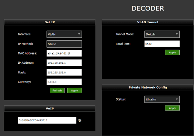
Establishing an Internet connection
Notes:
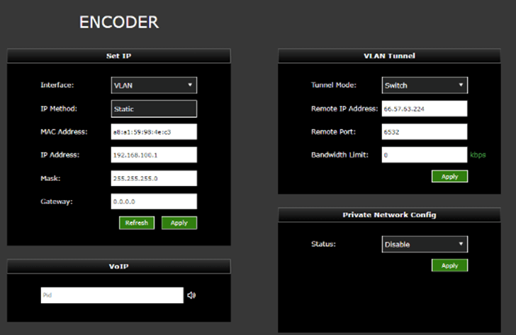
- IP Addresses can be static or dynamically assigned (DHCP), and can be assigned to interface Eth0 which is used for primary RPS functionality, or assigned to Eth1, which is used for the VLAN tunnel.
- The physical ports Lan1 / Lan2 and logical designations Eth0 and Eth1, are reversed:
LAN2 = Eth0. Primary communications
LAN1=Eth1. VLAN tunnel functionality
To set up an internet connection for the encoder using a DHCP or static IP method, complete the following steps:
- Use the default interface settings ‘Eth0’ and ‘IP Method’ in the Set IP pane if you use DHCP. Click the Refresh button in the Set IP pane. The IP address, Mask, and Gateway fields should automatically populate.
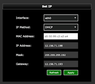
- If you use a static IP address, click Eth1 from the Interface drop-down menu. Click the IP method drop-down menu and select Static. Enter your desired IP address, Mask and Gateway.
- Click Apply to save your settings.
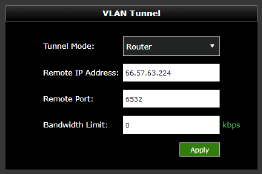
VLAN Tunnel configuration overview
Note: IP Addresses can be static or DHCP and assigned to interface eth0 which is used for primary RPS functionality, or assigned to eth1, which is used for the VLAN tunnel.
By default, VLAN configuration automatically populates. In addition, the VLAN tunnel is designed to be a “set it and forget it” network between the encoder and decoder and distributes IP address accordingly using DHCP.
Suppose the user would like to perform an advanced VLAN configuration. In that case, the VLAN tunnel settings can be used to network several devices connected to an encoder through a local switch or view the encoder Web UI from the decoder network. The VLAN Tunnel supports IP Intercom, IP Tally, or CCU.
Subnet rules: The IP addresses assigned to eth1 for each device can be any desired subnet configuration as long as they are separated enough not to conflict with one another in a DHCP environment.
For example:
- You can use 10.0.1.1 and 10.0.200.1
- Do not use 10.0.1.1 and 10.0.1.20
VLAN Tunnel configuration
The VLAN Tunnel setting pane configures the VLAN tunnel functionality by inputting the IP address of the decoder, port, and bandwidth limit (optional). The port is associated with 6532 by default and can be changed if desired. Refer to the latest TVU port forwarding guidelines for more information.
To change the VLAN tunnel (Router) settings, enter your change(s) in the VLAN tunnel pane and click Apply.
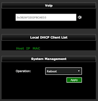
VoIP configuration
The VoIP settings pane allows the user to enter the PID of the decoder into the encoder’s VoIP settings pane to establish communication between the encoder and decoder.
To configure VoIP complete the following steps:
- In the VoIP pane, enter the full PID number of the encoder.
- Click the speaker icon to initiate the call.
TVU VLAN Tunnel Switch mode
The VLAN Tunnel Switch mode:
- Provides support for TVU Switch via VLAN Tunnel (Layer 2 connectivity)- User can now switch between standard VLAN tunnel and TVU Switch-based VLAN tunnel.
- Without network configuration, remote networking devices become true plug-and-play devices using TVU Switch. This allows the DHCP connectivity to work with any device when connected to the TVU Encoder or Decoder.
To configure VLAN Switch mode on the Encoder (router client):
- Open to the Encoder setup page. In the VLAN Tunnel panel select Switch from the Tunnel Mode drop-down menu.
- Enter the Remote IP Address of the Decoder.
- Leave the Remote Port set to the default 6532 and click Apply.
- In the Set IP panel, allow the VLAN IP, Mask, and Gateway defaults as shown in the following “Encoder (router client) configuration” figure.
To configure VLAN Switch mode on the Decoder (router server):
- Open the Decoder setup page.
- Select Switch from the Tunnel Mode drop-down menu in the VLAN Tunnel panel and click Apply.
- In the Set IP panel, assign the required VLAN IP, Mask, and Gateway as per your requirement and click Apply.
- In the Set IP panel, allow the VLAN IP, Mask, and Gateway defaults as shown in the following “Decoder (router server) configuration” figure.
The Local DHCP client list in the following “Decoder (router server) configuration” displays the IP/MAC address of the clients connected to the Encoder and Decoder VLAN port.
VLAN Tunnel Switch Mode basic setup diagram
Note: When in Switch mode, the decoder is the DHCP server and the encoder is the router client.

Dual live decoder support
Using this method, the user can push the RPS Encoder streams to both Decoder 1 and Decoder 2 or Producer and Decoder 2.
When using TVU Producer, the user needs to select the check box next to TVU Producer which will prompt the user to add the login and password for a producer VM session.
To support two live decoders simultaneously, complete the following steps:
- In the RPS user interface Decoder 2 IP Address settings panel, click the checkbox as shown in “Enable dual live decoder settings.”
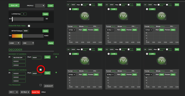
- Enter the Decoder 2 IP address and port number.
- Click Apply.
Closed Caption support
There is no specific setting in the RPS user interface for Closed Captions. The user must connect the closed caption source to the Encoder and Decoder to output the CC video in the output.
NTP configuration
The NTP configuration panel allows users to configure the encoder and decoder as local NTP servers in a closed network. If you are using RPS in a closed network without internet access, you must use the “Customized” setting for NTP configuration.
To configure NTP, complete the following steps:
- Click the Mode drop-down menu in the NTP Config pane and select a mode.
- To customize the NTP Configuration mode, select Customized from the drop-down menu. Then, enter the Server IP address of the decoder and leave the Port number 123.
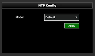
- Click Apply to save your settings.
Output video format
The Output video setting panel allows users to select the output resolution and framerate of all of the channels that are coming from the encoder.
- Select a Video format from the drop-down menu in the Output Video format pane.
- Click Apply.
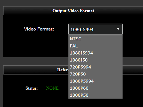
Video status in the encoder settings pane
Users can monitor video input formats and status in the RPS GUI status window. The GUI will show the format of each video input on the Encoder and the received video format for the Return Video.
RPS encoder Web interface configuration settings
Open the TVU RPS Web interface to configure the encoder settings.
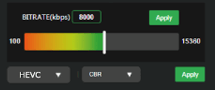
Edit the bitrate and delay
To edit the bitrate and delay settings, complete the following steps:
- Click the Global Bitrate Value check box in the RPS Web interface.
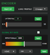
- Enter your preferred Bitrate (kbps) value in the provided field and click Apply.
- Enter your preferred Latency (delay) value in the provided field and click Apply.
- To select a bitrate control, click the Bitrate Control VBR drop-down menu to select a value:
- VBR + Average Priority: (is the preferred default average priority)
- VBR + Channel Priority: (is the preferred channel priority)
- CBR: (is a fixed or constant bitrate variable)
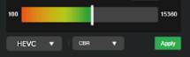
Editing the CODEC
The H.264 and HEVC (H.265) options allow users to select which CODEC to use. HEVC allows better throughput with a lower bitrate setting.
To edit the CODEC setting, complete the following steps:
- Click the drop-down menu and select H.264 or HEVC from the menu.
- Click the drop-down menu and select CBR or VBR from the menu.
- Click Apply.
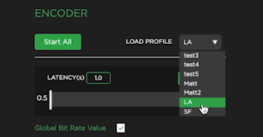
Save, load, and delete profile features
The Load profile feature in the Encoder panel allows users to save encoder profiles for later use. For example, if an encoder is moved from one location to another, the encoder profile settings can be recalled and applied to that specific location.
To save an encoder profile, complete the following steps:
- Enter your settings in the Encoder pane and click Apply for each change.
- Enter a Setting name in the Save setting field on the window‘s bottom right side. Then, click Save.
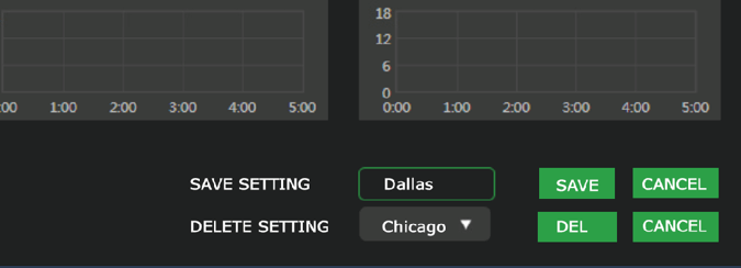
A pop-up message confirms the saved profile.
- To load a saved profile, click the Load profile drop-down menu in the Encoder panel and select a saved profile.
Autolive function
If an encoder or decoder is powered off when live, when that encoder powers on again, it will automatically go live with the last receiver it had been live with.
Enabling Decoder Control
To access the encoder GUI via the decoder IP, complete the following steps:
- Enable the check box in the Enable Decoder Control panel.
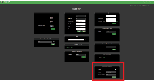
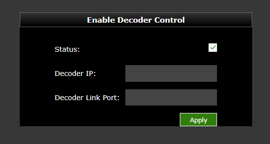
- Enter the decoder IP and 22222 as the Decoder Link Port.
- The Decoder setting panel, enter port 22222 for port-forwarding when the decoders are in a different LAN.
- Use [Decoder IP]:8080/rps/ to access the encoder GUI.
Channel status in the encoder GUI
If there is no network connection on the encoder, the status will display as OFFLINE.
Status indicators are as follows:
- If the encoder is online, the status will display “Standby” in green.
- If the set decoder is connected (and ports are open) to the encoder, the status will remain green but display “Online.”
- A red “LIVE“ status will only appear if a decoder receives the signal successfully.
- If a video input is unplugged during live transmission, that specific channel will be green and display “Online.”
RPS decoder configuration settings
In the Decoder panel of the RPS Web interface, a user can encode to a single decoder. A user can also encode two separate decoders simultaneously. Encoding to 2 decoders allows users to create 2 independent programs using the same sources.
Set the decoder 1 IP address
To set the decoder IP address, complete the following steps:
- In the Decoder 1 IP address IP field, enter your primary decoder’s static IP address, source name, or PID.
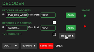
- Enter your first port number in the First Port field. The default port range begins with 10001. If you want to use another port range, you will need a total of 10 ports in a sequence.
For example, a new port range would be:
20081-20091 (input would start at port 20081)
IP and port changes are not editable when in live mode.
- Click Apply.
Set the decoder 2 IP address
- To encode to a secondary decoder, enter the Decoder 2 IP address IP field, the static IP address, source name, or PID.
- Enter your first port number in the First Port field. The default port range begins with 10001. If you want to use another port range, you will need a total of 10 ports in a sequence.
- Click the checkbox to enable the decoder.
- Click Apply.
Note: both transmissions are unicast to the individual decoder. Extra bandwidth is required to support two outbound transmissions.
Decoder status indicator LEDs
The status indicator LEDs in the Decoder panel indicate the connection status between the encoder and decoder. The status indicators are as follows:
Green – Operational and connected
Red – Offline or the port is not open
Transmitting to Producer
The RPS to Producer function allows a user to pair four channels of an RPS encoder with TVU Producer. Only channels 1-4 are supported and only support 2-channel audio. When an encoder is transmitting to Producer, it is not possible to transmit to a second decoder. While transmitting from RPS to Producer, the signal is encoded as CBR.
When a user selects Producer in the Decoder section, Decoder 1 and 2 are disabled and displayed as grayed out. The user is also given a pop-up window to add their producer account.

Return Video
In the Return video panel, you can select where the return video feeds come from when using 2 decoders.
- Click the decoder drop-down menu to select a decoder.
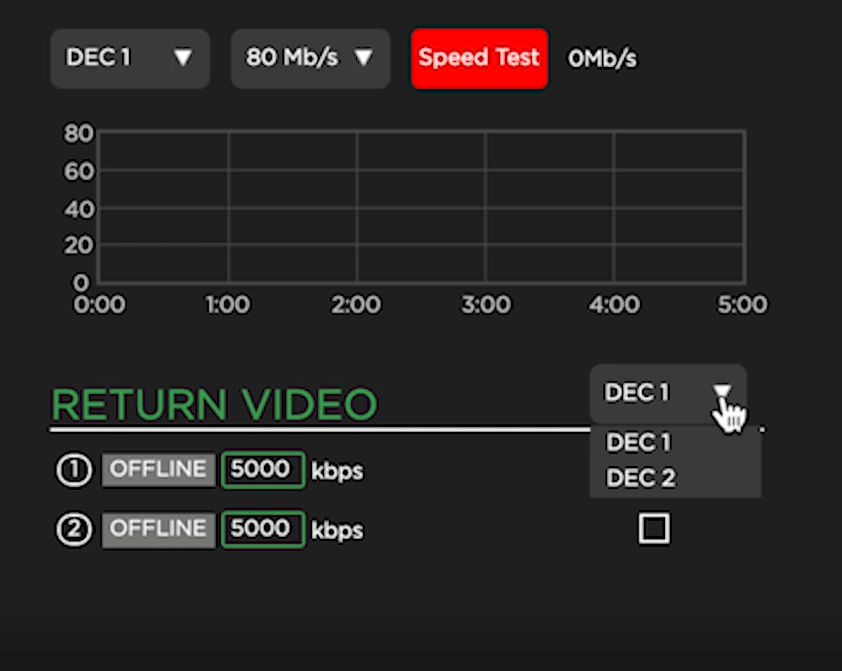
- To initiate a return video transmission, connect one or two SDI inputs to ports 7 and 8 on the rear panel of the decoder. Then, connect one or two SDI inputs to ports 7 and 8 on the rear panel of the encoder.
The encoder to decoder “Return Video” port settings 1 and 2 must be synchronized, for example:
(1) Port 7 (encoder) to the decoder (port 7).
(2) Port 8 (encoder) to the decoder (port 8)
Complete the following steps to route the video to the decoder to enable the field to see what is being transmitted:
- To enable a preview, you must disable a station video feed in the Return Video pane. The example shows port (2) offline.

- To enable a bitrate change, recheck the bitrate check box.
Note: Bitrate can be changed during a live preview.
IMPORTANT: Only 4 Main transmissions are possible when using 2 Return Video Feeds.
The user can go live with up to 6 main transmissions with a maximum of 2 video returns simultaneously.
- The Quad card model uses ports 7 and 8 for returns.
- The Duo card model uses ports 3 and 4 for returns when it is not using main transmissions.

The example below shows both stations (1) and (2) Offline.

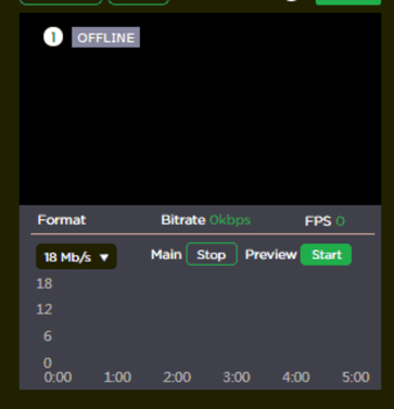
Encode Channel Monitor operations and settings
To start a transmission, complete the following steps:
- In the Encode Channel Monitor pane, click Start.
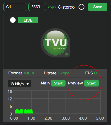
- You can mouse over the upper left field and rename your channel.
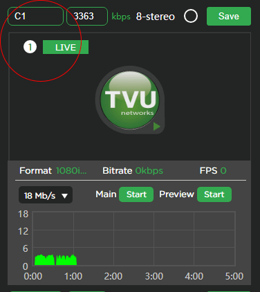
- To change the individual channel bitrate, uncheck the bitrate check box shown in Edit the bitrate and delay. Then make the bitrate change. Then, click Save.
- To choose 8-channel stereo, select the 8-stereo check box. Then, click Save.

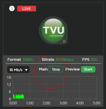
- To move your transmission into the Live mode, Click the “Main” Start button. When your production is Live, the Preview window will indicate Live mode in red, and the “Main” button will display “Stop”.
Video preview rules
Typically, active preview configurations are: 6 main + 0 previews, 5 main + 1 preview, and 4 main + 4 previews.
If all six sources are active, click the Main Stop button to stop a source. Then, click the Preview Start button to view a new Preview.
RPS 4-channel Web interface overview
The RPS v6.3 and higher 4-channel configuration uses the same TVU VS3500 server with the Duo 2 card in place of the standard Quad 2 card. The hardware is the same as our standard TVU RPS Transceiver which comes with the Duo 2 card.
When a Duo 2 card is detected on the system, the main Web interface shows 4 previews instead of the standard 6 previews. The previews for the 4-channel configuration are much larger than the standard 6-channel version, as shown in the following figure.
4-channel preview
- The Preview start/stop button has been replaced with a preview eye logo. Clicking the eye logo will turn the preview picture On and Off.
- The Format, Bitrate, FPS, and Preview (eye logo) are located above the preview window.
6-channel preview
The Format, Bitrate, FPS, and Preview display below the preview window.
4 primary live channels
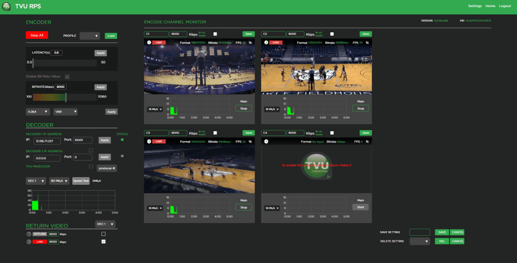
The following figure shows 4 primary live channels.

3-channels primary plus 1 return video
The following figure shows 3-channels primary plus 1 return video.

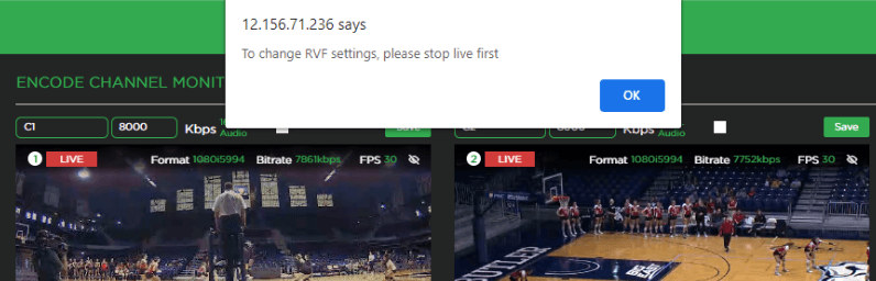
To enable or disable the return video feed, complete the following steps:
- Click Stop All to stop all of the primary transmission channels.
If the user tries to enable or disable return video with the primary transmission live, the warning message “To change RVF settings, please stop live first” displays.
- Once the primary live transmission is stopped, enable or disable a single or both return video feeds. This depends on the operator’s requirement.
- To resume primary transmission live, click Start All or click Start under the Main tab for the individual primary channel.
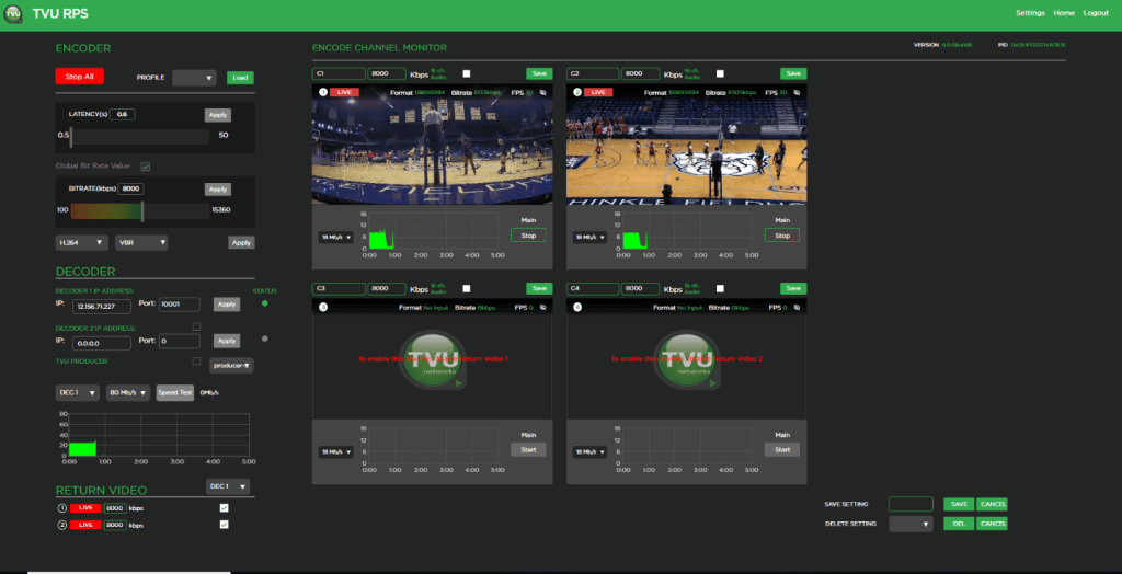
3-channels primary plus 1 live return video
The following figure shows 3 primary channels and 1 return live video feed where channels 1, 2, and 3 are primary, and channel 4 is the return feed.
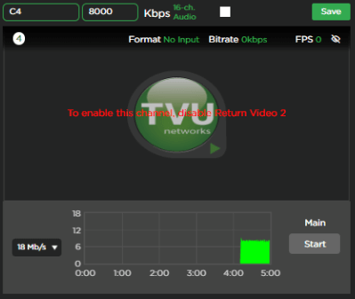
2-channels primary plus 2 return video
The following figure shows 2 primary channels and 2 return live video feeds where channels 1 and 2 are primary and 3 and 4 are return feeds.
If the operator is using 2 primary and 2 returns and decides to turn ON the primary transmission again on channels 3 and 4, the operator must complete the following steps:
- Click Stop All. Then, disable the return video feed by unchecking the box under the RETURN VIDEO section.
- Click Start All.
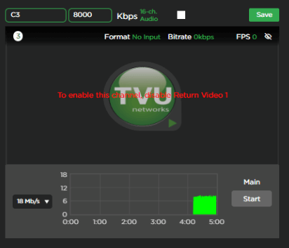
The message displays “To enable this channel (channel 3), disable Return Video 1” and “To enable this channel (channel 4), disable Return Video 2” as shown in the following figures.
Note: This feature should be possible for both 4 and 6 channel versions.
Chapter 2 – Monitor client feature
The Monitor Client feature is now available for RPS v6.3 and higher.
Overview
The primary purpose of the Monitor client feature is to allow a user to monitor outputs from decoders in different locations. For example, a user monitoring their own decoder’s outputs in New York can also monitor the outputs of a decoder in Tokyo.
This is accomplished by passing output channels 1-6 of the Tokyo decoder to the New York decoder as video streams in ISSP format.
Alternatively, if the user wants to monitor these channel streams in a different stream decoder, such as the VLC software application, the streams can also be formatted as SRT video.
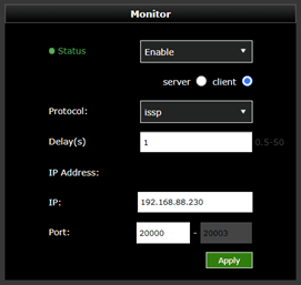
Setting up the Monitor Client connection
To establish the monitor client connection between a remote decoder-1 in location A to decoder-2 in location B, complete the following steps:
- Open the decoder setting page and scroll to the Monitor tab.
- Click the Status drop-down tab and select Enable.
- Select the server radio button.
- Click the Protocol drop-down menu and select ISSP or SRT.
- Leave the default Port as 20001. Note that you can set any port between 20000-21000 if needed.
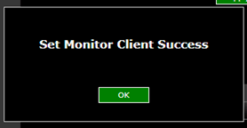
- Click Apply to save your settings.
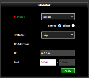
- After clicking Apply, a success message displays to confirm your settings.
- The Status indicator in the Monitor panel changes from red to green.
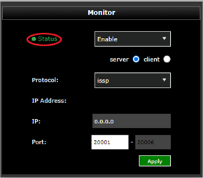
To establish the monitor client connection for decoder-2:
- Open the decoder setting page and scroll to the Monitor tab.
- Click the Status drop-down tab and select Enable.
- Select the client radio button.
- Click the Protocol drop-down menu and select ISSP.
- In the Delay field, enter a delay (in seconds).
- In the IP Address field, enter the decoder-1 IP address.
- Leave the default Port as 20001. Note that you can set any port between 20000-21000 if needed.
- Click Apply to save your settings. The user will now see the same decoder-1 output for the decoder-2 output.
To send the decoder-1 output stream to a TVU transceiver, complete the following steps:
- Open the decoder setting page and scroll to the Monitor tab.
- Click the Status drop-down tab, select Enable.
- Select the server radio button.
- Click the Protocol drop-down menu and select ISSP.
- Leave the default Port as 20001. Note that you can set any port between 20000-21000 if needed.
- Click Apply to save your settings.
- In the TVU Transceiver user interface, enter the following ISSP URL as an Ext IP source input and go live:
srt://IP_address_dec:port
For example:
If the decoder-1 IP address is 192.168.88.230 and set to port 20001, enter the ISSP URL as: issp://192.168.88.230:20001 as an Ext IP source input on the transceiver where port 20001 is for channel-1. Similarly, if you want to pull channel-2 from decoder-1, use port 20002 in the ISSP URL, and apply the same method for channels-3, 4, 5, and 6, where the ports used will be 20003, 20004, 20005, 20006.
Note: The monitor client feature should only be enabled on the initial TVU Transceiver that is distributing the streams. The secondary transceiver/decoder software does not require this feature to receive the streams.
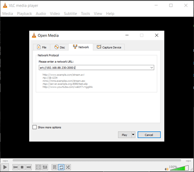
Sending the decoder output to an SRT decoder
To send the decoder-1 output stream to an SRT decoder such as a VLC Player, complete the following steps:
- Open the decoder setting page and scroll to the Monitor tab.
- Click the Status drop-down tab and select Enable.
- Select the server radio button.
- Click the Protocol drop-down menu and select SRT.
- Leave the default port as 20001 for the decoder-1 channel-1 output stream.
- Enter port 20002 for the channel-2 output stream
- Enter port 20003 for the channel-3 output stream
- Enter port 20004 for the channel-4 output stream
- Enter port 20005 for the channel-5 output stream
- Enter port 20006 for the channel-6 output stream
- Click Apply to save your settings.
- In the VLC Player under Media > Network stream tab, enter the following SRT URL. Then, click Play:
srt://IP_address_dec:port
For example, enter srt://192.168.88.230:20001 if you are using the channel-1 decoder-1 output stream.
Note: The last digit of the port number is equal to the channel number. Therefore port 20001 is for channel 1, port 20002 is for channel 2, etc., up to port 20006 for channel 6.
If the operator uses the return video feed, the SDI IN cables must be removed and replaced with the SDI OUT cables on ports 3 and 4 for both the encoder and decoder.
If the encoder receives SDI video input on ports 3 and 4, the operator must remove the SDI video input cables and connect them to ports 3 and 4 on the decoder.
To view the return video feed on the SDI monitor, remove the SDI out cables from ports 3 and 4 on the decoder and connect them to ports 3 and 4 on the encoder.
Use WebRTC for web GUI preview
The RPS v6.3 and higher 4-channel configuration also supports WebRTC for a web GUI preview where the latency for preview is as low as 200 ms.
Low Latency mode for fixed lines
The RPS v6.3 and higher 4-channel configuration supports a low latency mode of up to 0.6 seconds between the encoder and decoder for closed and open networks.
Chapter 3 – Product Specifications
Chapter 3 – Applications overview
TVU RPS provides the following production solutions and applications:
- TVU RPS supports 1080p/1080i/720p HD and NTSC and PAL formats.
- The system uses TVU’s Inverse Statmux Plus (IS+) transmission algorithm for stable, high-quality, low-latency transmissions. The system’s simple web interface gives real-time previews of all six channels and allows users to monitor and control all aspects of the transmission, including current bitrate and latency.
- TVU RPS provides multi-camera remote production for live coverage without the costs associated with expensive dedicated fiber or satellite links, extensive dedicated transmission equipment, and large on-site production crews.
- TVU RPS features a VLAN tunnel that allows IP devices in the field to connect virtually to the LAN in the studio, making it ideal for teleprompters, tally, remote cameras, and more.
- TVU’s VoIP solution, TVU Voice, is also compatible with TVU RPS, making communication between the field and headquarters easier than ever.
Applications
- 6 Channel Remote Multi-cam or Remote Studio Application
- 4 Channel Remote Multi-cam or Remote Studio Application with 2 Channel Return Video
- Remote Production System VLAN Tunnel Application – IP Intercom
- Remote Production System VLAN Tunnel Application – IP Tally
- Remote Production System VLAN Tunnel Application – CCU
© Copyright 2024 TVU Networks Corporation. All rights reserved in all media.
Document Part Number: TVU RPSVS3500 Software Setup Guide Rev F EN 03-2024