Contents
- Introduction, setup, and base operation
- About this guide
- Features overview
- TVU RPS Link Web interface
- Access the RPS Link via Command Center
- TVU RPS Link encoder configuration
- Private Network configuration
- RPS encoder Web interface configuration
- RPS decoder configuration
- Channel monitor operations/settings
- Web interface overviews
- Product specifications
- Applications overview
- Introduction, setup, and base operation
- Features overview
- About this guide
- TVU RPS Web interface
- Network requirements and configuration
- Front/Rear panel overviews
- Setup and configuration guide
- RPS receiver (decoder) setup
- TVU RPS Link encoder settings
- Private Network configuration
- VLAN Tunnel, VoIP, and Output configurations
- RPS decoder server settings
- Log in – RPS Link Web UI
- Hardware configurations
- Product specifications
- Applications overview
TVU RPS Link Encoder Software Setup Guide
TVU RPS Link is a complete and versatile IP video solution designed specifically for REMI production. TVU RPS Link combines the TVU RPS encoder and TVU Rack Router into a single package for REMI production over aggregated wired or wireless connections.
Chapter 1 – Introduction, setup, and base operation
The RPS Link is an IS+ encoder in a 2RU rack-mount form factor. The RPS Link provides the same primary performance and features as the standard 4 or 6-channel RPS encoder and includes onboard Wifi and a Hotspot with external antennas. The RPS Link functional status can be viewed from the front panel LCD, and you can access the six SIM card slots from the front panel. The RPS Link works seamlessly with the standard RPS decoder and is fully compatible with the TVU Cloud ecosystem.
Product overview
The RPS Link transmitter encodes up to six synchronized SDI sources. It transmits high-quality, low-latency IP video from the remote location to a studio-based TVU RPS receiver, which decodes six accurately synchronized SDI outputs. The user-friendly RPS Link interface grants control over all aspects of transmission, including bitrate and latency, and provides previews of all four channels with the Duo 2 card and all six channels with the Quad 2 card. Channel and slot operations can be monitored by using the Encoder Channel Monitor and Slot Monitor tabs in the top panel of the RPS Link user interface.
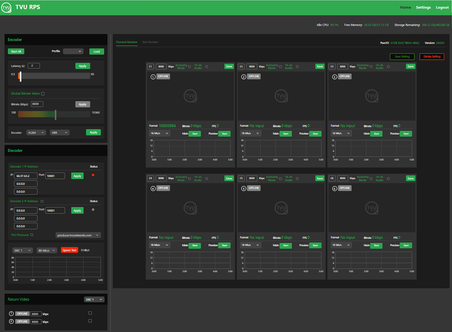
TVU RPS Link Web interface, Channel Monitor tab
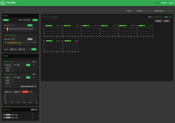
TVU RPS Link Web interface, Slot Monitor tab
TVU RPS Link provides up to two low-latency return video feeds from the studio to the field. VLAN tunnels on RPS decoders enable communication between the studio and the field over a private network.
About this guide
This user guide will enable you to:
- Describe the contents and key features of the RPS Link Remote Production System.
- Log into the RPS Web interface.
- Describe the RPS Web user interface monitoring and control functions.
- Perform encoder and decoder VLAN Tunnel, VoIP, and NTP configurations.
- Set up the encoder to transmit to two decoders simultaneously for redundancy or two independent programs using the same sources.
Features
- Supports up to six fully synchronized multi-channel transmissions. Supports the 6-channel Quad 2 and 4-channel Duo 2 cards.
- Super low-latency transmission over commodity internet. Glass-to-glass latency as low as 500ms over cellular networks and Ethernet.
- It includes multiple encode behaviors to suit virtually any network environment.
- The RPS sends metadata and control from the studio to the field using the VLAN Tunnel.
- Supports up to 16-channels of SDI embedded audio or 8-channels of HDMI embedded audio.
- High-quality, low latency video feed of the live program from the station via HDMI. Up to two low-latency return video feeds sent from the studio back out to the field.
- Connect to virtually any live professional or consumer video device via 6G-SDI or HDMI 2.0a input including cameras, video routers, pool-feeds, video switchers, video players and more.
- Aggregates any mix of cellular, Ethernet, and WiFi.
- It supports up to six embedded LTE or 5G modems. Ships standard with external IP67-rated external LTE antennas (3m cables included) or optional 5G antennas.
- It can support a mix of 5G (optional) /LTE/4G and 3G modems (internal to the chassis) with external SMA antenna connections (4x SMA per 5G Modem, 2x SMA per LTE modem). The RPS Link allows modem antennas to be connected directly to the chassis itself, simplifying cabling.
- It Auto-senses and supports virtually all video formats including 4K (25/30P), 1080p, 1080i, 720p, and NTSC/PAL transmission using HEVC or H.264 VBR or CBR encoding (300K-50Mb/s).
- File upload management: Upload files from the field using a connected USB device (thumb drive or HDD/SSD) with file management capability (package dependent).
- Web-based ConfigT interface for local or remote monitoring and control.
- Easily accessible front panel SIM card slots for easy configuration.
- Front panel LCD interface for easy configuration, control and monitoring.
- Embedded outbound WiFi module with external antenna support (MIMO) for use with IS+ transmissions.
- Embedded Hotspot WiFi module with external antenna support (MIMO) for access point use (Internet connectivity).
- Support for TVU Return Video Feed via SDI Din ports 7 and 8 on the DeckLink Quad2 card and SDI ports 3 and 4 on the DeckLink Duo2 card port.
- Talkback support using either TVU Voice (2-way voice) or traditional IFB (package dependent).
- Supported as a source when used with TVU Partyline for collaboration.
- Optional dual power supply
- Works seamlessly with the standard TVU RPS decoder.
- The RPS Link encoder has an easy-to-use browser interface accessible using the TVU RPS Web interface or your TVU Command Center account.
- Directly compatible with the TVU Cloud production tools, including TVU Command Center, TVU Producer, TVU Partyline, TVU CloudR, and TVU Channel.
Setup guide
This Setup guide provides instructions to complete the following topics:
- Setting up the TVU RPS VS3500 encoder and RPS decoder.
- Log in to the RPS interface and access it using your Command Center account.
- Configuring the TVU RPS Link encoder and RPS decoder using the RPS Web interface or Command Center.
- Operating the TVU RPS Link encoder and RPS decoder.
Before you begin
Complete the procedures in the TVU RPS Link Hardware Set Up Guide to set up the TVU RPS Link transmitter (encoder) and VS3500 receiver (decoder) hardware.
IMPORTANT: The RPS Link TE5700 V7 supports the 12th generation CPU platform only. If you are using the 11th generation CPU platform, continue to use the previous software build 65107. Refer to the units label for the RPS Link version and use the appropriate documentation.
Logging in to the TVU RPS Link Web interface
After the unit is set up and powered on, monitoring and control of the system are performed with the TVU RPS Link Web interface, which is hosted on the encoder. This interface is also accessible through the Command Center user interface.
To log in to the TVU RPS Link Web interface, have your encoder static IP address available and complete the following procedure.
Log in to the RPS Link Web interface
- Open a Web browser window and enter:
http://IP_Address/rps/index.html
(Where the IP_Address is your Encoder static IP address)
- Click Enter. The login pop-up displays.
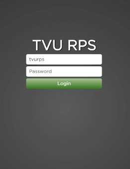
- To Log in to the RPS Link Web interface, Enter the following using all lowercase letters:
User ID: tvurps
Password: Enter the last 8-digits of the PID using all caps
- Click Login. The TVU RPS Link Web interface displays.
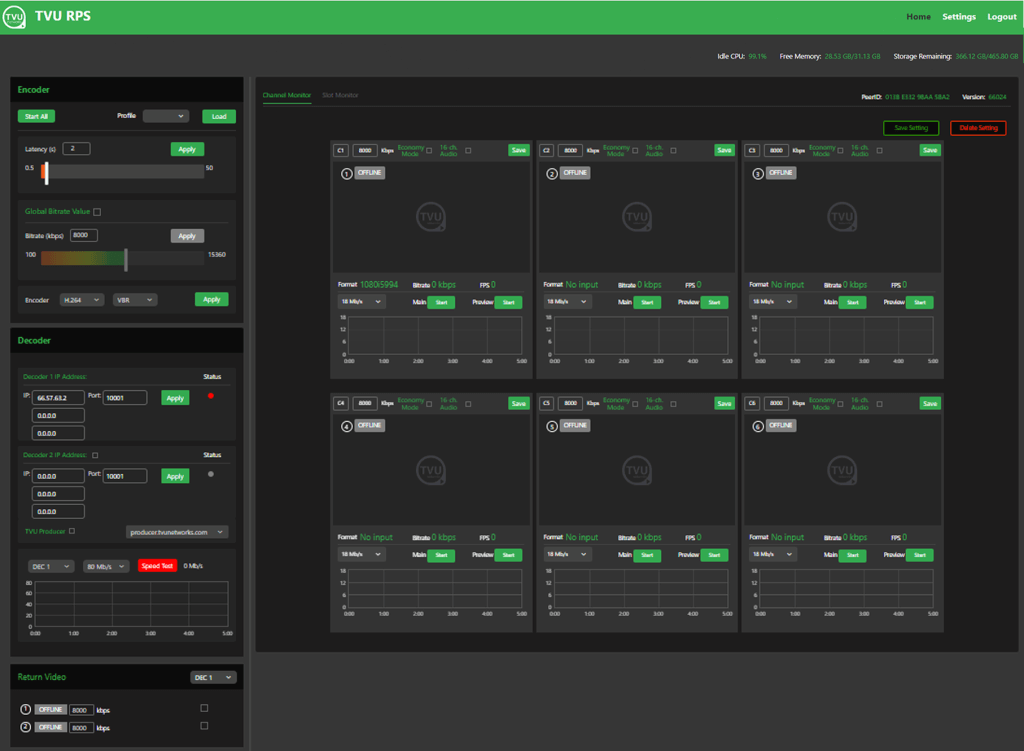
TVU RPS Link Web interface
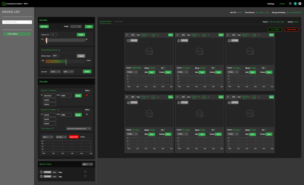
You will use the TVU RPS Link Web interface to monitor and control all aspects of transmission, including real-time previews of all four channels with the Duo 2 card and all six channels with the Quad 2 card, current bitrate, and latency. The RPS Web interface has the following controls and functions.
Encoder controls and functions
(1) The Encoder panel
(2) The Encoder Channel Monitor tab and Slot Monitor tab
(3) Settings menu – The Settings tab/menu
(4) The Return Video panel
(5) The Decoder panel
(6) Bitrate controls
(7) Real-time display for CPU Idle, Free Memory, and Storage Remaining
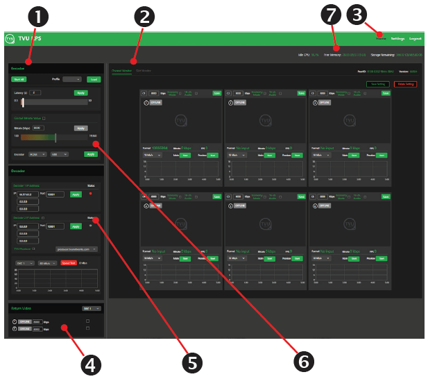
TVU RPS Link Web interface, 6 channel
RPS 4-channel Duo 2 PCI Express card
The Duo 2 PCI Express capture and playback card features 4 independent 3G-SDI connections. The card supports SDI formats in SD and HD up to 1080p60 with the flexibility of 4 separate capture or playback cards in one.
TVU RPS Link Web interface, 4 channel
Accessing the TVU RPS Link Web interface using Command Center
The RPS Link user interface can be added to your Command Center account and accessed from within Command Center. With the Command Center interface, a user can control transmission virtually anywhere.
To access the TVU RPS Link Web interface using the TVU Command Center, complete the following steps:
- Log in to Command Center, click the services navigation icon in the top-right panel of the Command Center Web interface, and select RPS.
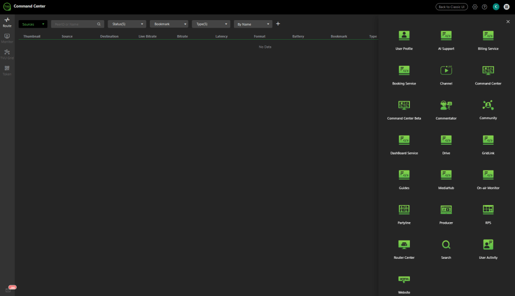
TVU Command Center Web interface – TVU Services
The Command Center RPS page displays. The current encoder does not support HTTPS access if the following error page is displayed. Click the Copy URL button and paste the link into a new browser window.
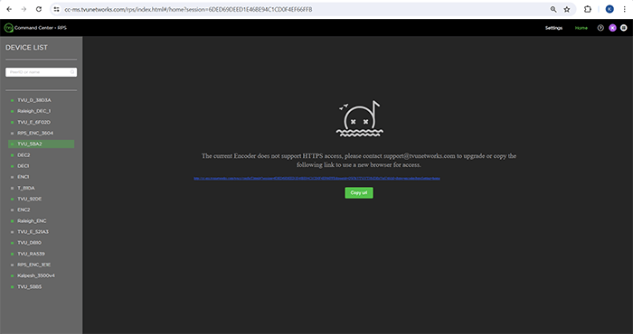
- Select the Encoder you want to control in the Device list.
The Command Center RPS Web interface Home screen displays the Device List and RPS Web interface. It has two tabs: Channel Monitor and Slot Monitor.
You will use the TVU RPS Link Web interface to monitor and control all aspects of transmission, including real-time previews of all six channels, current bitrate, and latency.
Command Center RPS interface
Note: Using the RPS Link Web interface from Command Center does not support video streaming from the encoder to the cloud.
Encoder and decoder settings
The encoder and decoder setup pages display slightly different information. However, they accomplish the same goals and are accessible using an HDMI out connection, VGA connection, or a web browser. After the RPS VS3500 decoder is powered on and the splash screen briefly appears, the decoder server settings screen displays.
RPS Link Settings overview
Complete the remaining steps to access the TVU RPS Link encoder Settings using the RPS Link Web interface:
- From the Encoder Web interface Home screen, click Settings in the top-right panel of the RPS Web interface.
- Click the Encoder tab at the top of the screen.
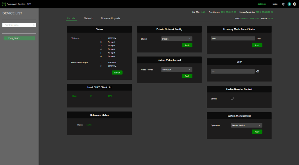
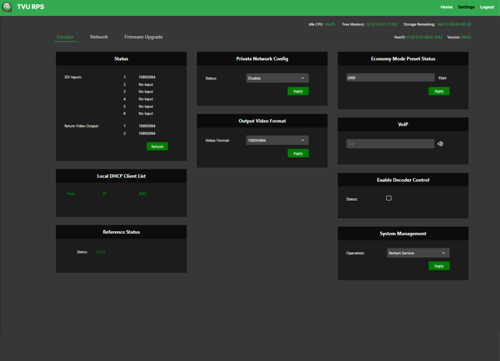
The Encoder settings window displays. The Encoder settings screen includes three tabs in the top navigation. Use these tabs to access the Encoder settings, Network settings, and Firmware Upgrade screens.
The Encoder tab incudes the following panels:
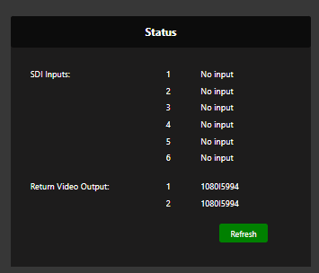
- Status – SDI Inputs 1-6 and Return Video Outputs for decoders 1 and 2.
- Local DHCP Client List – Host, IP, and MAC.
- Reference Status – Displays reference status.
- Private Network Config – Disable and enable selections.
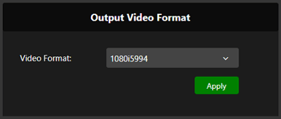
- Output Video Format – Video Format selections.
- Economy Mode Preset Status – Configure preset status in Kbps.
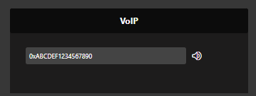
- VoIP – Enter the PID and click the Speaker icon to initiate the call.
- Enable Decoder Control – Checkbox to enable decoder control.
- System Management – The System Management panel allows users to Restart Service and Reboot.
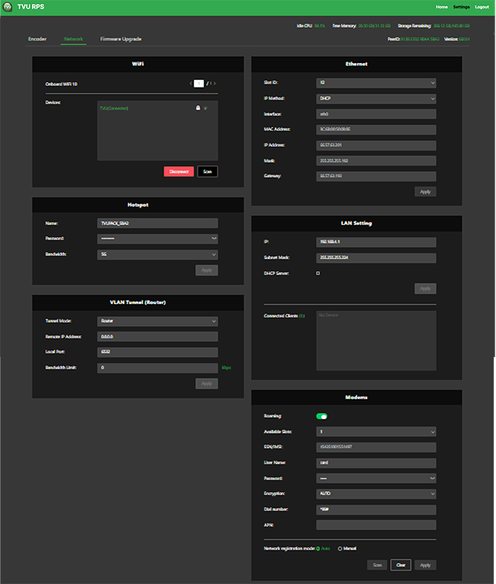
The Network tab provides configuration information for:
- WiFi
- Hotspot
- VLAN Tunnel (Router)
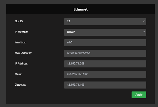
- Ethernet
- LAN Setting
- Modems
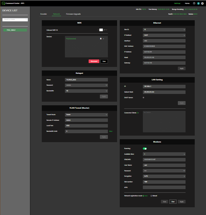
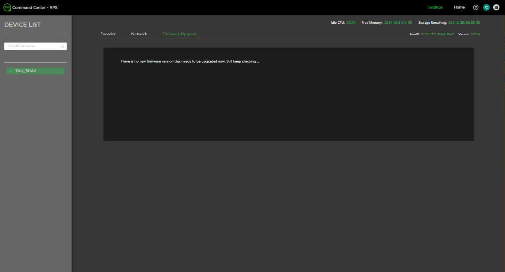
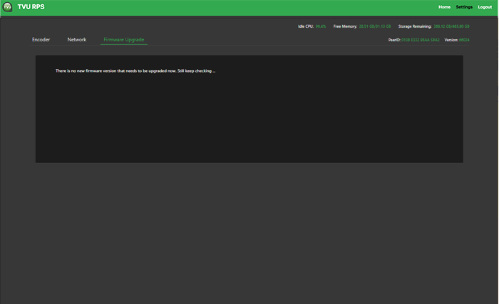
The Firmware Upgrade tab allows users to upgrade the firmware for embedded wireless modems as required.
Configuring the RPS Link encoder and decoder
The TVU RPS Link Web interface allows users to configure the TVU RPS Link encoder and RPS decoder. The following procedures can be used to configure the encoder and decoder.
Complete the remaining steps to configure the TVU RPS Link encoder settings using the RPS Link Web interface:
Establishing an Internet connection
Notes:
- IP Addresses can be static or DHCP and assigned to interface eth0, which is used for primary RPS functionality, or assigned to eth1, which is used for the VLAN tunnel.
- The physical ports Lan1 / Lan2 and logical designations Eth0 and Eth1, are reversed:
LAN2 = Eth0. Primary communications
LAN1=Eth1. VLAN tunnel functionality
To set up an internet connection for the encoder using a DHCP or static IP method, complete the following steps:
- Click the Network tab. In the Ethernet panel, use the default interface setting ‘Eth0’ and ‘IP Method’ if you use DHCP.
- The IP address, Mask, and Gateway fields should automatically populate. Click the Apply button to save your settings.
- If you use a static IP address, click the IP Method drop-down menu and select Static. Enter your desired IP address, Mask, and Gateway.
- Click Apply to save your settings.
VLAN Tunnel (Router) configuration overview
By default, VLAN configuration automatically populates. In addition, the VLAN tunnel is designed to be a “set it and forget it” network between the encoder and decoder and distributes IP addresses accordingly using DHCP.
If the user would like to perform an advanced VLAN configuration, the VLAN tunnel settings can be used to network several devices connected to an encoder by using a local switch or to view the encoder Web UI from the decoder network. The VLAN Tunnel supports IP Intercom, IP Tally, or CCU.
Subnet rules:
The IP addresses assigned to eth1 for each side of the VLAN tunnel must be on different subnets. The VLAN tunnel routes between networks.
For example:
- For the encoder, use: 192.168.100.1/255.255.255.0
- For the decoder, use: 192.168.101.1/255.255.255.0
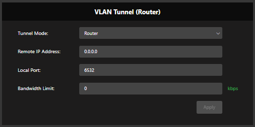
VLAN Tunnel (Router) configuration
The VLAN Tunnel setting pane configures the VLAN tunnel functionality by inputting the IP address of the decoder, port, and bandwidth limit (optional). The port is associated with 6532 by default and can be changed if desired. Refer to the TVU port forwarding guidelines for more information.
- To change the VLAN tunnel (Router) settings, click Settings > Network tab.
- Enter your change(s) in the VLAN tunnel (Router) panel and click Apply.
VoIP configuration
The VoIP settings pane allows the user to enter the PID of the decoder into the encoder’s VoIP settings panel to establish communication between the encoder and decoder.
To configure VoIP, complete the following steps:
- Click Settings > Encoder tab.
- In the VoIP panel, enter the full PID number of the encoder in the Pid field.
- Click the speaker icon to initiate the call.
Private Network configuration
The Private Network configuration panel allows the user to enable the encoder and decoder as a private network.
To configure a private network, complete the following steps:
- Click the Encoder tab.
- Click the Status drop-down menu in the Private Network Config panel and select Enable.
- Point the server to the Decoder by replacing 127.0.0.1 with the Decoder IP address.
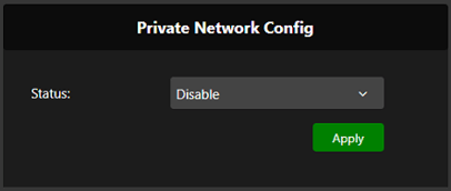
- Click Apply to save your settings.
Output video format
The Output video setting panel allows users to select the output resolution and framerate of all channels from the encoder.
- Click Settings > Encoder tab.
- In the Output Video format panel, select a Video format from the drop-down menu and click Apply.
Video status in the encoder settings pane
Users can monitor video input formats and status in the Command Center RPS GUI. Click Settings > Encoder tab to view the status pane. The GUI would show the format of each video input on the Encoder and the received video format for the Return Video.
RPS Link encoder Web interface configuration settings
Open the TVU RPS Link Web interface to configure the encoder settings.
Edit the bitrate and delay
To edit the bitrate and delay settings, click the Home tab in the top navigation panel and complete the following steps:
- Click the Global Bitrate Value check box in the RPS Web interface.
- Enter your preferred Bitrate (kbps) value in the provided field and click Apply.
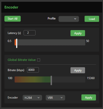
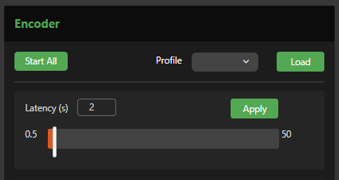
- Enter your preferred Latency (delay) value in the provided field and click Apply.
- To select a bitrate control, click the Bitrate Control VBR drop-down menu to select a value:
- VBR + Average Priority (is the preferred default average priority)
- VBR + Channel Priority (is the preferred channel priority)
- CBR (is a fixed or constant bitrate variable)
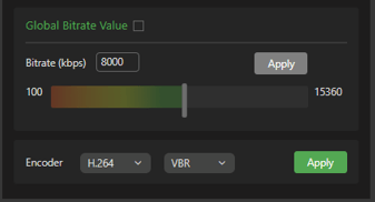
Editing the CODEC
The H.264 and HEVC (H.265) options allow users to select the preferred CODEC. HEVC allows better throughput with a lower bitrate setting.
To edit the CODEC setting, complete the following steps:
- Click the Home tab in the top navigation panel.
- Click the drop-down menu and select H.264 or HEVC from the menu.
- Click the drop-down menu and select CBR or VBR from the menu.
- Click Apply.
Save, load, and delete profile features
The Load profile feature in the Encoder panel allows users to save encoder profiles for later use. For example, if an encoder is moved from one location to another, the encoder profile settings can be recalled and applied to that specific location.
To save an encoder profile, complete the following steps:
- Enter your settings in the Encoder pane and click Apply for each change.
- Enter a Setting name in the Save setting field on the window’s bottom right side. Then, click the Save Setting button.

A pop-up message confirms the saved profile.
- To load a saved profile, click the Load profile drop-down menu in the Encoder panel and select a saved profile.
Autolive function
If an encoder or decoder is powered off when live, when that encoder powers on again, it will automatically go live with the last receiver it had been live with.
Channel status in the encoder GUI
If there is no network connection on the encoder, the status will display as OFFLINE.
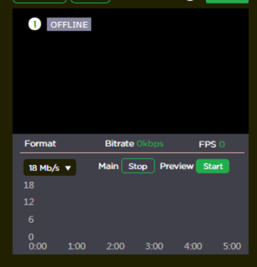
Status indicators are as follows:
- If the encoder is online, the status will display “Standby” in green.
- If the set decoder is connected (and ports are open) to the encoder, the status will remain green but display “Online.”
- A red LIVE status would only appear if a decoder successfully receives the signal.
- If a video input is unplugged during live transmission, that channel will be green and display “Online.”
RPS decoder configuration settings
In the Decoder panel of the RPS Web interface, a user can encode to a single decoder. A user can also encode two separate decoders simultaneously. Encoding to 2 decoders allows users to create 2 independent programs using the same sources.
Set the decoder 1 IP address
To set the decoder IP address, complete the following steps:
- In the Decoder 1 IP address IP field, enter your primary decoder’s IP address.
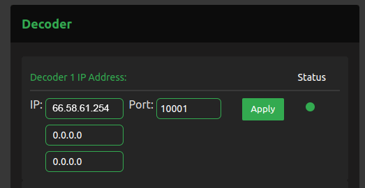
- Enter your first port number in the First Port field. The port range default is 10001. You will need 10 ports maximum in a sequence if you want to use another port range.
For example, a new port range would be:
20081-20091 (input would start at port 20081)
IP and port changes are not editable when in live mode.
- Click Apply.
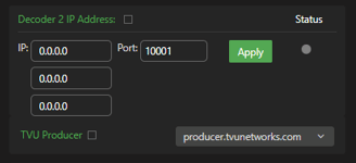
Set the decoder 2 IP address
- To encode to a secondary decoder, enter the Decoder 2 IP address in the Decoder 2 IP address field.

- Enter your first port number in the First Port field. The port range default is 10001. You will need 10 ports maximum in a sequence if you want to use another port range.
- Click the Decoder 2 IP Address checkbox to enable the decoder.
- Click Apply.
Note: both transmissions are unicast to the individual decoder. Extra bandwidth is required to support two outbound transmissions.
Decoder status indicator LEDs
The status indicator LEDs in the Decoder panel indicate the connection status between the encoder and decoder. The status indicators are as follows:
- Green – operational and connected
- Red – offline, or the port is not open
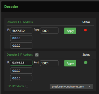
Transmitting to TVU Producer
The RPS to Producer function allows a user to pair four channels of an RPS encoder with TVU Producer. Channels 1-6 are supported and only support 2-channel audio. The encoder is dedicated to transmitting only to TVU Producer and cannot transmit to a second decoder. Please note that when transmitting to TVU Producer, the output will be in CBR mode of Channels 1 to 6 with 2-channel audio.
When a user selects Producer in the Decoder section, the Decoder 1 and 2 options are unavailable and displayed as grayed out. The user is also provided a pop-up window to add their TVU Producer account.
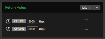
Return Video
In the Return video panel, you can select where the return video feeds come from when using 2 decoders.
- Click the DEC 1 drop-down menu to select a decoder.
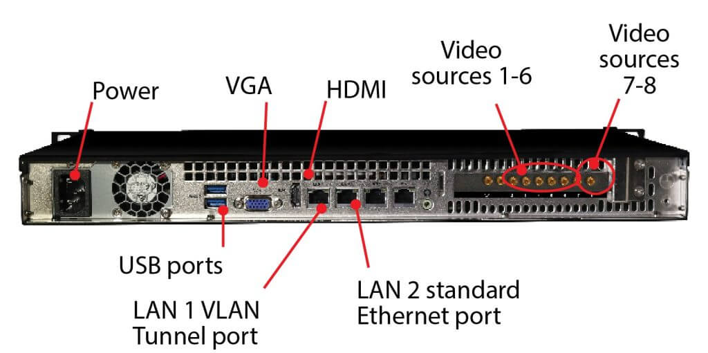
- To initiate a return video transmission, connect one or two SDI inputs to ports 7 and 8 on the rear panel of the decoder. Then connect one or two SDI inputs to ports 7 and 8 on the rear panel of the encoder.
The encoder to decoder “Return Video” port settings 1 and 2 must be synchronized, for example:
- (1) Port 7 (encoder) to the decoder (port 7)
- (2) Port 8 (encoder) to the decoder (port 8)
Complete the following steps to route the video to the decoder to enable the field to see what is being transmitted.
- Disable a station video feed in the Return Video pane to enable a preview. The example shows port (2) offline.
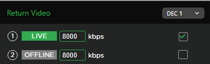
- To enable a bitrate change, check the bitrate checkbox.
The bitrate can be changed during a live preview.
IMPORTANT: 6 Main transmissions are possible when using 2 Return Video Feeds with 1080i.
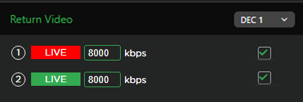
The example below shows both stations (1) and (2) offline.
Channel Monitor operations and settings
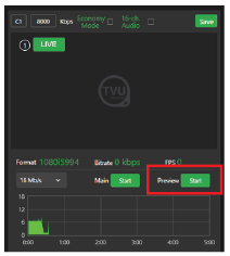
To start a transmission, complete the following steps:
- Click the Channel Monitor tab. In the Encode Channel Monitor panel, click the Preview Start button.
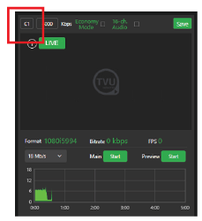
- You can mouse over the upper left field and rename your channel.
- To change the individual channel bitrate, uncheck the Global bitrate checkbox shown in “Edit the bitrate and delay”
- . Make the bitrate change and click Save.
- To choose 16-channel audio, select the 16-channel audio check box. Then, click Save.
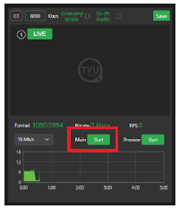
- To move your transmission into the Live mode, Click the “Main” Start button. When your production is Live, the Preview window will indicate Live mode in red, and the “Main” button will display “Stop.”
Video preview rules
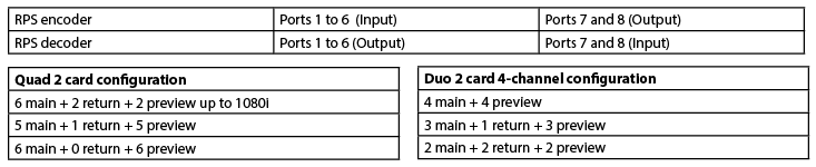
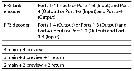
Typically, active preview configurations are: 6 main + 0 previews, 5 main + 1 preview, and 4 main + 4 previews.
It is possible to run 6 channels, 6 previews and 2 return feeds simultaneously (up to 1080i).
- If all six sources are active, click the Main Stop button to stop a source. Then, click the Preview Start button to view a new Preview.
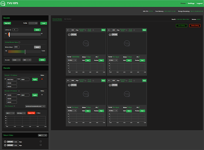
RPS Link 4-channel Web interface overview
The RPS Link 4-channel configuration uses the same TVU VS3500 decoder with the Duo 2 card instead of the standard Quad 2 card. The hardware is the same as our standard TVU RPS Transceiver, which comes with the Duo 2 card.
When a Duo 2 card is detected on the system, the main Web interface shows four previews instead of the standard 6 previews.

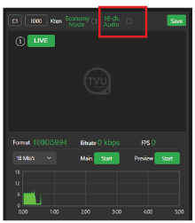
4-channel preview
Clicking the Preview start/stop button will turn the preview picture On and Off
The Format, Bitrate, FPS, and Preview Start button are located below the preview window.
6-channel preview
The Format, Bitrate, FPS, and Preview display below the preview window.
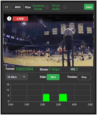
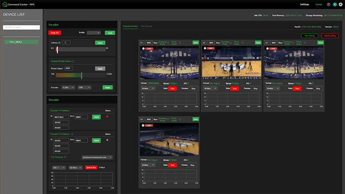
4 primary live channels
The following figure shows 4 primary live channels.
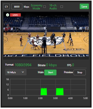
3 primary channels plus 1 return video
The following figure shows 3 primary channels plus 1 return video.
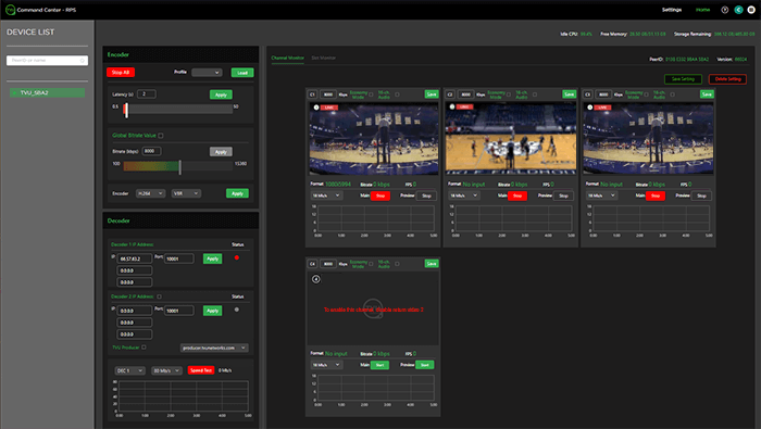
To enable or disable the return video feed, complete the following steps:
- Click Stop All in the Encoder panel to stop all of the primary transmission channels.
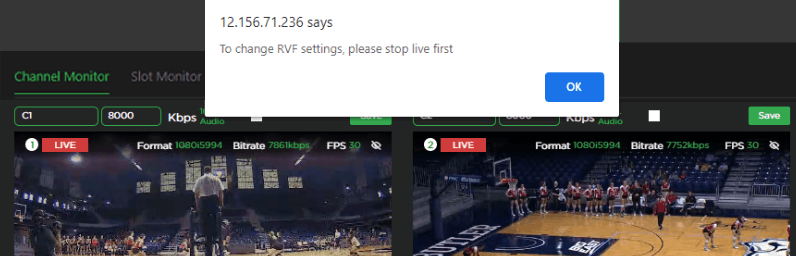
If the user tries to enable or disable return video while the primary transmission is still live, the warning message “To change RVF settings, please stop live first” displays.
- Once the primary live transmission is stopped, the operator can enable or disable the return video feeds as needed.
- To resume the live primary transmission, click the Start All button in the Encoder panel or click the Main Start button.
3 primary channels plus 1 live return video
The following figure shows 3 primary channels and 1 return live video feed where channels 1, 2, and 3 are primary, and channel 4 is the return feed.
2 primary channels plus 2 return video
The following figure shows 2 primary channels and 2 return live video feeds where channels 1 and 2 are primary and 3 and 4 are return feeds.
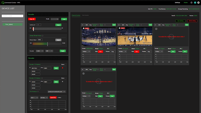
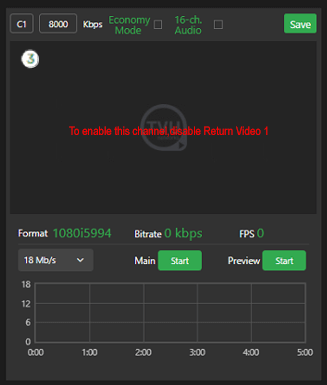
If the operator is using 2 primary channels and 2 returns and decides to turn ON the primary transmission again on channels 3 and 4, the operator must complete the following steps:
- Click the Stop All button in the Encoder panel, then disable the return video feed by unchecking the box under the Return Video panel.
- Click Start All.
The message displays “To enable this channel (channel 3), disable Return Video 1” and “To enable this channel (channel 4), disable Return Video 2,” as shown in the following figures.

If the operator uses the return video feed, the SDI IN cables must be removed and replaced with the SDI OUT cables on ports 3 and 4 for both the encoder and decoder.
If the encoder receives SDI video input on ports 3 and 4, the operator must remove the SDI video input cables and connect them to ports 3 and 4 on the decoder.
The SDI out cables connected to ports 3 and 4 on the decoder must be removed and connected to ports 3 and 4 on the encoder to view the return video feed on the SDI monitor.
Use WebRTC for web GUI preview
The RPS Link 4-channel configuration also supports WebRTC for a web GUI preview where the latency for preview is as low as 200 ms.
Low Latency mode for fixed lines
The RPS Link 4-channel configuration supports a low latency mode of up to 0.6 seconds between the encoder and decoder for closed and open networks.
Note: This feature should be possible for both 4 and 6 channel versions.
Chapter 2 – Product Specifications
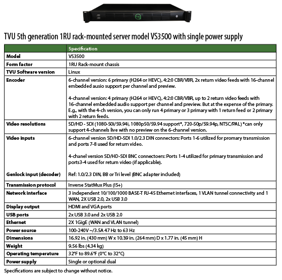
1RU rack-mounted server model VS3500 with single power supply
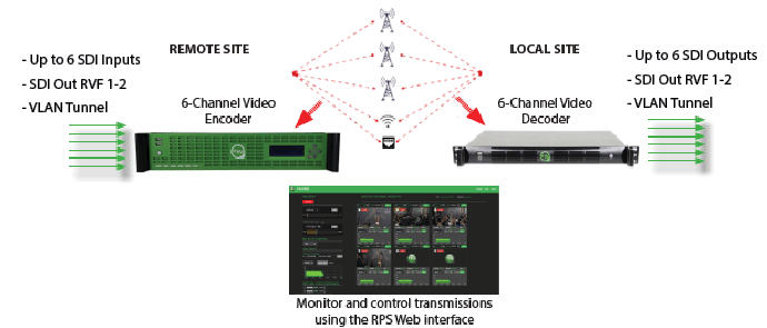
TVU RPS Link production solutions and applications
- TVU RPS Link supports 1080p/1080i/720p HD, NTSC, and PAL formats.
- The system uses TVU’s Inverse Statmux Plus (IS+) transmission algorithm for stable, high-quality, low-latency transmissions. The system’s simple web interface gives real-time previews of all six channels. It allows users to monitor and control all aspects of the transmission, including current bit rate and latency.
- TVU RPS Link provides multi-camera remote production for live coverage without the costs associated with expensive dedicated fiber or satellite links, extensive dedicated transmission equipment, and large on-site production crews.
- TVU RPS Link features a VLAN tunnel to allow IP devices in the field to virtually connect to the LAN in the studio, making it ideal for teleprompters, tally, remote cameras, and more.
- TVU’s VoIP solution, TVU Voice, is also compatible with TVU RPS Link, making communication between the field and headquarters easier.
Applications
- 6-Channel Remote Multi-cam or Remote Studio Application
- 4-Channel Remote Multi-cam or Remote Studio Application with – Channel Return Video
- Remote Production System VLAN Tunnel Application – IP Intercom
- Remote Production System VLAN Tunnel Application – IP Tally
- Remote Production System VLAN Tunnel Application – CCU
© Copyright 2024 TVU Networks Corporation. All rights reserved in all media.
Document Part Number: TVU RPS Link Software Setup Guide Rev C EN 07-2024
TVU RPS Link is a complete and versatile IP video solution designed specifically for REMI production. TVU RPS Link combines the TVU RPS encoder and TVU Rack Router into a single package for REMI production over aggregated wired or wireless connections.
IMPORTANT: The RPS Link TE5700 V7 supports the 12th generation CPU platform only. If you are using the 11th generation CPU platform, continue to use the previous software build 65107. Refer to the units label for the RPS Link version and use the appropriate documentation.
Chapter 1 – Introduction, setup, and base operation
The RPS Link is an IS+ encoder in a 2RU rack-mount form factor. The RPS Link provides the same primary performance and features as the standard 4 or 6-channel RPS encoder and includes onboard Wifi and a Hotspot with external antennas. The RPS Link functional status can be viewed from the front panel LCD, and you can access the six SIM card slots from the front panel. The RPS Link works seamlessly with the standard RPS decoder and is fully compatible with the TVU Cloud ecosystem.
Product overview
The RPS Link transmitter encodes up to six synchronized SDI sources. It transmits high-quality, low-latency IP video from the remote location to a studio-based TVU RPS receiver, which decodes six accurately synchronized SDI outputs. The user-friendly RPS Link interface grants control over all aspects of transmission, including bitrate and latency, and provides previews of all four channels with the Duo 2 card and all six channels with the Quad 2 card.
TVU RPS Link provides up to two low-latency return video feeds from the studio to the field. VLAN tunnels on RPS decoders enable communication between the studio and the field over a private network.
Features
- Supports up to six fully synchronized multi-channel transmissions. Supports the 6-channel Quad 2 and 4-channel Duo 2 cards.
- Super low-latency transmission over commodity internet. Glass-to-glass latency is as low as 500ms over cellular networks and Ethernet.
- It includes multiple encode behaviors to suit virtually any network environment.
- The RPS sends metadata and control from the studio to the field using the VLAN Tunnel.
- Supports up to 16 channels of SDI-embedded audio or 8 channels of HDMI-embedded audio.
- A high-quality, low-latency video feed of the live program from the station via HDMI. Up to two low-latency return video feeds from the studio back to the field.
- Connect to virtually any live professional or consumer video device via 6G-SDI or HDMI 2.0a input, including cameras, routers, pool feeds, switchers, video players, and more.
- Aggregates any mix of cellular, Ethernet, and WiFi.
- It supports up to six embedded LTE or 5G modems. It ships standard with external IP67-rated external LTE antennas (3m cables included) or optional 5G antennas.
- It can support a mix of 5G (optional) /LTE/4G and 3G modems (internal to the chassis) with external SMA antenna connections (4x SMA per 5G Modem, 2x SMA per LTE modem). The RPS Link allows modem antennas to connect directly to the chassis, simplifying cabling.
- It auto-senses and supports virtually all video formats, including 4K (25/30P), 1080p, 1080i, 720p, and NTSC/PAL transmission using HEVC or H.264 VBR or CBR encoding (300K-50Mb/s).
- File upload management: Upload files from the field using a connected USB device (thumb drive or HDD/SSD) with file management capability (package dependent).
- Web-based ConfigT interface for local or remote monitoring and control.
- Easily accessible front panel SIM card slots for easy configuration.
- Front panel LCD interface for easy configuration, control, and monitoring.
- Embedded outbound WiFi module with external antenna support (MIMO) for use with IS+ transmissions.
- Embedded HotSpot Wifi module with external antenna support (MIMO) for access point use (Internet connectivity).
- There is support for TVU Return Video Feed via SDI Din ports 7 and 8 on the DeckLink Quad2 card and SDI ports 3 and 4 on the DeckLink Duo2 card port.
- Talkback support uses TVU Voice (2-way voice) or traditional IFB (package dependent).
- Supported as a source when used with TVU Partyline for collaboration.
- Optional dual power supply
- Works seamlessly with the standard TVU RPS decoder.
- The RPS Link encoder has an easy-to-use browser interface accessible using the TVU RPS Web interface or your TVU Command Center account.
- Directly compatible with the TVU Cloud production tools, including TVU Command Center, TVU Producer, TVU Partyline, TVU CloudR, and TVU Channel.
About this guide
This user guide will enable you to:
- Set up the RPS Link encoder and RPS decoder hardware.
- Operate the faceplate controls and operations panel
- Configure the RPS Link encoder IP address.
- Configure the RPS Link encoder and decoder ports.
- Log into the RPS Web interface.
Components
TVU RPS Link includes the following:
- TVU MLink transmitter (encoder)
- Two WiFi MIMO antennas
- LTE dome antenna
- 5G modem antenna
- 18x 2.3 DIN to BNC male adapter cables, BB or Tri-level (BNC adapter)
TVU RPS Web interface
After the unit is set up and powered on, monitoring and control of the system is performed with the TVU RPS Link Web interface, which is hosted on the encoder. This interface is also accessible through the Command Center user interface.
You will use the TVU RPS MLink Web interface to monitor and control all aspects of transmission, including real-time previews of all four channels with the Duo 2 card and all six channels with the Quad 2 card, current bitrate, and latency.
For more information about setting up the RPS Link with the 4-channel Duo 2 card, refer to “Hardware configuration options.”
Network requirements
TVU Networks® recommends that you assign a static IP address to the RPS decoder to ensure the network configuration remains stable.
Contact TVU Networks support if you want to use a configuration other than the one specified in the this hardware set up guide.
Router and firewall configuration
Complete the following steps to configure your router or firewall:
- Permit all UDP incoming traffic for port 10001 at the receiver (video).
- Permit both TCP and UDP incoming traffic for port 10010.
- Permit TCP incoming traffic for port 10009.
- Permit all UDP incoming traffic for port 6532 at the receiver (VLAN Tunnel).
- For VoIP services, permit outbound traffic to ports 9001, 9091.
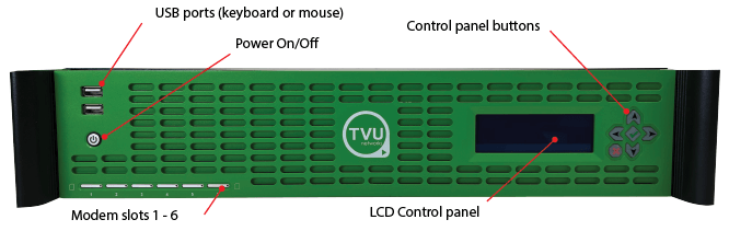
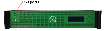
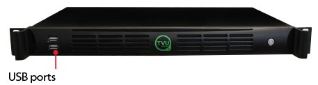
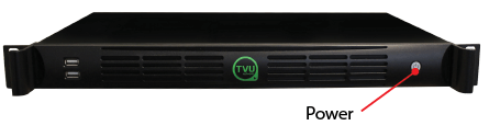
Front panel overview
The TVU RPS Link encoder and decoder front panel feature two USB 2.0 ports and the power on/off button.
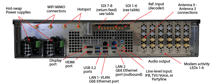
Rear panel overview – Quad 2 card configuration
The TVU RPS Link encoder and decoder rear panel feature the following connections:
Rear panel overview – 4-channel Duo 2 card configuration
The TVU RPS Link encoder and decoder rear panel feature the following connections:
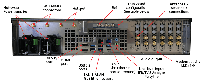
For SDI port mapping, refer to “Hardware configuration options.”
Encoder and decoder SDI port configuration table:
Note: The Duo 2 card 4-channel configuration supports WebRTC low-latency preview in the encoder web GUI.
Setup and configuration guide
This setup guide provides instructions to complete the following procedures:
- Setting up the TVU RPS Link encoder and RPS decoder
- Setting up the RPS Link encoder IP address
- Configuring the RPS Link encoder and RPS decoder ports
- Connecting WiFi and dome antennas.
- Front panel controls and operations
- Logging in to the RPS Link Web interface
- Configuring the RPS Link encoder and RPS decoder using the RPS Web interface.
Setting up the RPS Link encoder
Complete the following instructions to set up the RPS Link encoder and RPS decoder hardware.
Note: Refer to the port numbers printed on the adapter card when attaching the BNC cables, as the adapter may be oriented differently in the TE5700 chassis.
RPS Link (encoder) identification and setup procedure
The following procedure provides the steps necessary to identify and perform the initial setup for the RPS Link encoder with the 6-channel Quad 2 card.
If your RPS Link is using the 4-channel Duo 2 card refer to “Hardware configuration options” for set up information.
Complete the following steps to set up the TVU RPS Link transmitter (encoder):
All input sources must be the same video format and frame rate.
- Connect the factory-supplied AC power cable(s) to the RPS Link hot-swap power supplies and AC power source.
- Connect a computer display connector to the rear panel display or HDMI output port to view real-time system status.
- Connect a VLAN cable to the LAN1 GbE Ethernet port for VLAN connectivity on the rear panel.
- Connect an Ethernet cable to the LAN2 GbE Ethernet port for outbound connectivity on the rear panel.
- TVU IFB and VoIP service are provided using the USB audio box connected to the receiver. Connect your audio equipment as appropriate.
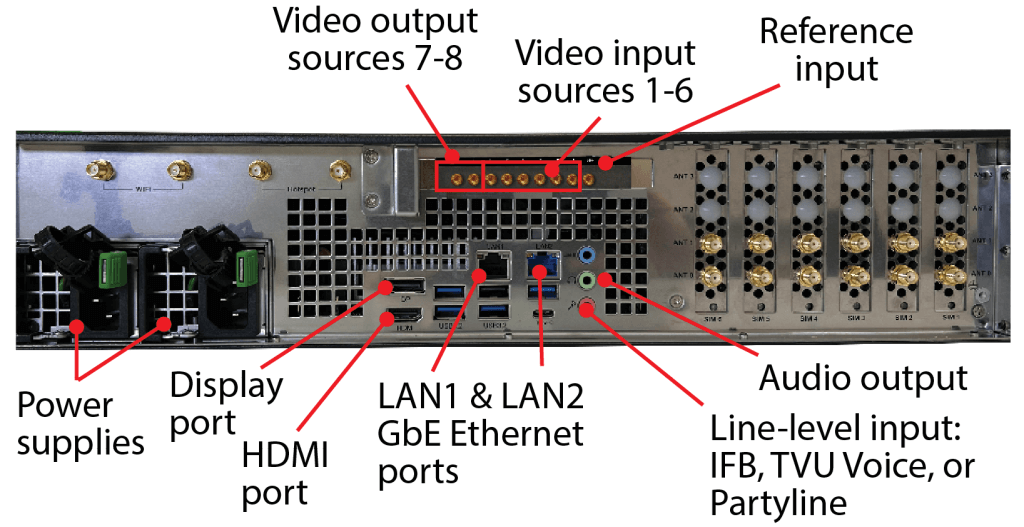
- Connect a keyboard and mouse to the encoder using the two front or rear panel USB ports.
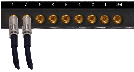
- Connect a factory-supplied 2.3 DIN to BNC male adapter cable to the decoder reference (Ref) input port.
Note: The RPS Link Quad2 card is installed in the upside down position starting with port 8 on the left side of the card.
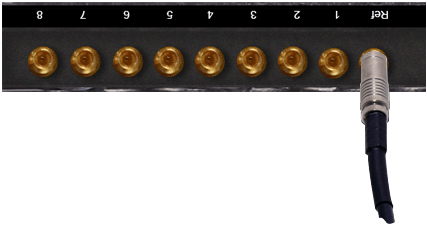
- Starting with port 6, connect 6 to 1 SD/HD-SDI video output sources to ports 1 to 6. Use the factory-supplied 2.3 DIN to BNC male adapter cables.
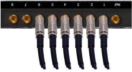
- Connect SD/HD-SDI return video sources to ports 7 and 8, starting with port 8 for the return video. Use the factory-supplied 2.3 DIN to BNC male adapter cables.
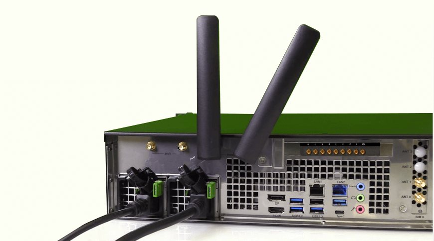
- If required, connect WiFi MIMO antennas to the top left WiFi connectors to support the MIMO mode configuration for LTE downloading (does not support uploading.)
- Connect the antenna connector to the modem connection on the rear panel:
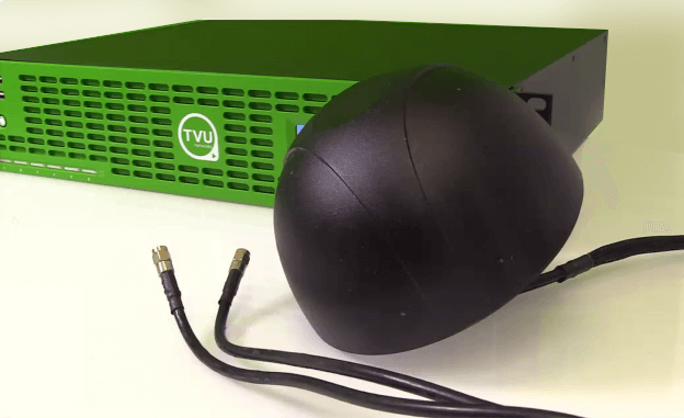
- 3 LTE dome antennas that use two modem ports each. One antenna supports 2 modems and should be installed at least 20 centimeters apart.
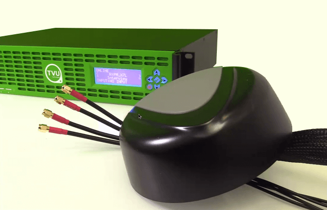
- 5G modem antennas (one per modem) with four connectors. Each 5G antenna connects to a single modem port. The 5G antenna should be installed at least 20 centimeters apart.
Powering the RPS Link on and off
Complete the following steps to power on/off and restart the RPS Link transmitter:
- To power on the RPS Link, press the power button in the front panel’s left lower section. The name and PID number of the unit displays on the RPS Link LCD screen during boot-up.
- To power off the RPS Link, press and hold the power button down for more than four seconds.
Note: The RPS Link will automatically restart if the power button is pressed and held in for less than four seconds.
RPS Link front LCD panel
The front panel’s LCD and button functionality is not currently supported.
The LCD panel displays the system PID and product information.
RPS receiver (decoder) and setup procedure
Complete the following steps to set up the TVU RPS VS3500 receiver (decoder):
- Connect the factory-supplied power cable to the decoder.
- Connect a monitor to the encoder using the HDMI or VGA connections.
- Connect the VLAN cable to the VLAN 1 port for VLAN tunnel support. Ports marked “LAN1” (the left port) are later encoder models.
- Connect an Ethernet cable to the following Ethernet port:
- LAN2 (second from left) is for a standard Ethernet connection.
- Connect a keyboard and mouse to the decoder using the two front or rear panel USB ports.
- Connect a factory-supplied 2.3 DIN to BNC male adapter cable to the decoder reference input (if required).
- Starting with port 1, connect 1 to 6 SD/HD-SDI video output sources to ports 1 to 6. Use the factory-supplied 2.3 DIN to BNC male adapter cables.
- Connect the SD/HD-SDI return video sources to ports 7 and 8 for the return video. Use the factory-supplied 2.3 DIN to BNC male adapter cables.
- Verify that the encoder and decoder are connected as described in the encoder and decoder setup procedures. Then, power on both units.
During boot-up, the “RPS Decoder” and “RPS Link Encoder” Web interfaces display on their respective monitors.
TVU RPS Link encoder settings
The encoder and decoder setup pages display slightly different information. However, they accomplish the same goals and are accessible using an HDMI out connection, VGA connection, or a web browser. After the encoder is powered on and the splash screen briefly appears, the encoder server settings screen displays.
You will use the TVU RPS Web interface to monitor and control all aspects of transmission, including real-time previews of all six channels, current bitrate, and latency. The RPS Web interface includes three tabs in the top navigation to access the Encoder settings, Network settings, and Firmware upgrade screens.
Establishing an Internet connection
Notes:
- IP Addresses can be static or DHCP and assigned to interface
eth0, which is used for primary RPS functionality, or assigned to eth1, which is used for the VLAN tunnel.- The physical ports Lan1 / Lan2 and logical designations Eth0
and Eth1, are reversed:
LAN2 = Eth0. Primary communications
LAN1=Eth1. VLAN tunnel functionality
To set up an internet connection for the encoder using a DHCP or static IP method, complete the following steps:
- Click Settings > Network tab. In the Ethernet panel, use the default slot ID ‘Eth0’ in the Interface field.
- IP Method dropdown options are Static or DHCP. The IP Address, Mask, and Gateway fields should automatically populate if DHCP is selected.
- The IP address, Mask, and Gateway fields should automatically populate. Click the Apply button to save your settings.
- If you use a static IP address, click the IP Method drop-down menu and select Static. Enter your desired IP address, Mask, and Gateway.
- Click Apply to save your settings.
Private Network configuration
The Private Network configuration panel allows the user to enable the encoder and decoder as a private network.
To configure a private network, complete the following steps:
- Click Settings > Encoder tab.
- Click the Status drop-down menu in the Private Network Config panel and select Enable.
- Point the server to the Decoder by replacing 127.0.0.1 with the Decoder IP address.
- Click Apply to save your settings.
VLAN Tunnel (Router) configuration overview
By default, VLAN configuration automatically populates. In addition, the VLAN tunnel is designed to be a “set it and forget it” network between the encoder and decoder and distributes IP addresses accordingly using DHCP.
If the user would like to perform an advanced VLAN configuration, the VLAN tunnel settings can be used to network several devices connected to an encoder by using a local switch or to view the encoder Web UI from the decoder network. The VLAN Tunnel supports IP Intercom, IP Tally, or CCU.
Subnet rules:
The IP addresses assigned to eth1 for each side of the VLAN tunnel must be on different subnets. The VLAN tunnel routes between networks.
For example:
- For the encoder, use: 192.168.100.1/255.255.255.0
- For the decoder, use: 192.168.101.1/255.255.255.0
VLAN Tunnel (Router) configuration
The VLAN Tunnel setting panel in the Network tab configures the VLAN tunnel functionality by inputting the IP address of the decoder, port, and bandwidth limit (optional). The port is associated with 6532 by default and can be changed if desired. Refer to the TVU port forwarding guidelines for more information.
To change the VLAN tunnel (Router) settings, enter your change(s) in the VLAN tunnel panel and click Apply.
VoIP configuration
The VoIP settings panel allows the user to enter the PID of the decoder into the encoder’s VoIP settings panel to establish communication between the encoder and decoder.
To configure VoIP, complete the following steps:
- Click Settings > Encoder tab. In the VoIP panel, enter the encoder’s entire PID number in the PID field.
- Click the speaker icon to initiate the call.
Output video format
The Output video setting panel allows a user to select the output resolution and framerate of all channels coming from the encoder.
Click Settings > Encoder tab. In the Output Video format panel, select a Video format from the drop-down menu and click Apply.
TVU RPS decoder server settings
The encoder and decoder setup pages display slightly different information. However, they accomplish the same goals and are accessible using an HDMI out connection, VGA connection, or a web browser.
After the decoder is powered on and the splash screen briefly appears, the decoder server settings screen displays.
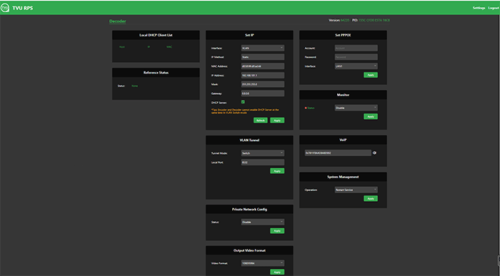
Establishing an Internet connection
Notes:
IP Addresses can be static or DHCP and assigned to interface eth0 which is used for primary RPS functionality, or assigned to eth1, which is used for the VLAN tunnel.The decoder IP address cannot be changed when VFB is enabled.
To set up an internet connection for the decoder, complete the following steps:
- If you use DHCP, click the Refresh button in the Set IP panel. The IP address, Mask, and Gateway fields should automatically populate.
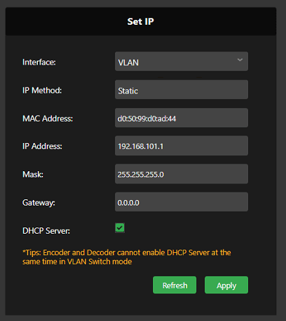
- If you use a static IP address, click the IP Method drop-down menu and select Static. Then, enter your desired IP address, Mask and Gateway.
- Click Apply to save your settings.
Logging in to the TVU RPS Link Web interface
To log in to the TVU RPS Link Web interface, have your encoder static IP address available and complete the following steps:
Log in to the RPS Link Web interface
- Open a Web browser window and enter:
http://IP_Address/rps/index.html
(Where IP_Address is your Encoder static IP address)
- Click Enter. The login pop-up displays.
- To Log in to the RPS Link Web interface, Enter the following using all lowercase letters:
User ID: tvurps
Password: Enter the last 8-digits of the PID using all caps
- Click Login. The TVU RPS Link Web interface displays.
Hardware configuration options
There are two hardware configurations for the RPS Link encoder described as follows:
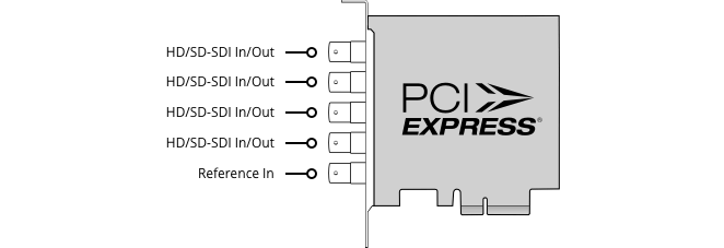
RPS 4-channel Duo 2 PCI Express card
The Duo 2 PCI Express, capture and playback card features 4 independent 3G-SDI connections. The card supports SDI formats in SD and HD up to 1080p60 with the flexibility of 4 separate capture or playback cards in one.
Connections:
- SDI Video Inputs – 4 x bidirectional 12-bit SD/HD independently configurable as either Input or Output.
- SDI Video Outputs – 4 x bidirectional 12-bit SD/HD independently configurable as either Input or Output.
- SDI Audio Inputs – 16 channels embedded in SD and HD.
- SDI Audio Outputs – 16 channels embedded in SD and HD.
- Sync Input – Tri-Sync or Black Burst.
- Server Interface – PCI Express 4 lane generation 2, compatible with 4, 8, and 16 lane PCI Express slots.
RPS Link 4-channel Web interface overview
The RPS Link encoder 4-channel configuration uses the same Duo 2 card instead of the standard Quad 2 card described in “TVU RPS Link rear panel connections.”
When a Duo 2 card is detected on the system, the main Web interface shows 4 previews instead of the standard 6 previews. The previews for the 4-channel configuration are much larger than the standard 6-channel version, as shown in the following figures.
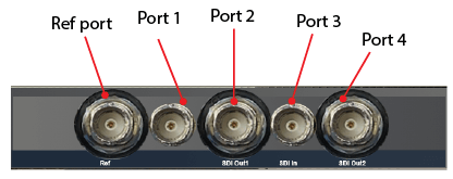
Port mapping 4-channel Duo 2 card
The port mapping for the RPS Link 4-channel configuration is from left to right. The leftmost port is the reference port, and to its right are Ports 1, 2, 3, and port 4. The reference port is used for Genlock. Port 1 is for primary channel 1, port 2 is for primary channel 2, port 3 is for primary channel 3 or return video feed 1, and port 4 is for primary channel 4 or return video feed 2.
Port 3 and port 4 can either be used as the primary channel or return feed. You cannot use the primary and return feed simultaneously as there is no separate dedicated port for the return feed as with the 6-channel version for the Quad 2 card (where ports 7 and 8 are for the return feed).
Encoder and decoder SDI port configuration table
Port configuration options
For information about port configurations, refer to the TVU Server Port-forwarding guidelines.
Chapter 2 – Product Specifications
1RU rack-mounted server model VS3500 with single power supply
TVU RPS Link production solutions and applications
- TVU RPS Link supports 1080p/1080i/720p HD, NTSC, and PAL formats.
- The system uses TVU’s Inverse Statmux Plus (IS+) transmission algorithm for stable, high-quality, low-latency transmissions. The system’s simple web interface gives real-time previews of all six channels. It allows users to monitor and control all aspects of the transmission, including current bit rate and latency.
- TVU RPS Link provides multi-camera remote production for live coverage without the costs associated with expensive dedicated fiber or satellite links, extensive dedicated transmission equipment, and large on-site production crews.
- TVU RPS Link features a VLAN tunnel to allow IP devices in the field to virtually connect to the LAN in the studio, making it ideal for teleprompters, tally, remote cameras, and more.
- TVU’s VoIP solution, TVU Voice, is also compatible with TVU RPS Link, making communication between the field and headquarters easier.
Applications
- 6-Channel Remote Multi-cam or Remote Studio Application
- 4-Channel Remote Multi-cam or Remote Studio Application with – Channel Return Video
- Remote Production System VLAN Tunnel Application – IP Intercom
- Remote Production System VLAN Tunnel Application – IP Tally
- Remote Production System VLAN Tunnel Application – CCU
© Copyright 2024 TVU Networks Corporation. All rights reserved in all media.