Contents
- Introduction, setup, and base operation
- Web User Interface overview
- Advanced features
- Advanced operations
- Advanced configuration and settings
- Linux server settings
- Settings – General panel
- Settings – Network setup
- Settings – File Browser
- Settings – Feature Control
- Settings – Grid Encoder
- Settings – SDI Output Setting
- Settings – Passthrough Streaming
- Settings – Transcriber
- Settings – Auto Record
- Settings – Auto Download
- Settings – IP Stream Out
- Settings – Live Encoder
- Settings – Locate All
- Settings – Set Location
- Settings – IP and Port mapping
- Settings – VLAN Setting
- Settings – Token Service
- Settings – Restart Service
- Service Control features
- Working with recorded content
- Data transmission panel – Live and record mode tabs
- File management
- Network and firewall configuration
- Network Diagnostics and Port Testing
TVU Servers Linux v8.2 Software User Guide
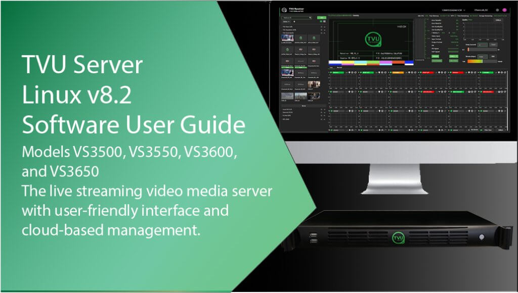
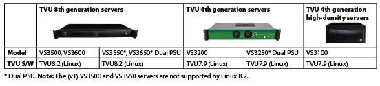
This TVU server software user guide for Linux provides information about setup, base operations, advanced operations, and configuration for TVU server models VS3500, VS3550, VS3600, and VS3650. Use Linux v7.9 for Models VS3100, VS3200, and VS3250.
IMPORTANT: It is recommended that only Models VS3500 and VS3550 (v2-v7) hardware be upgraded to the v8.2 software build. The VS3600 and VS3650 (v1-v7) hardware can be upgraded to the v8.2 software build.
Note: The VS3500/VS3550 (v1) hardware is not supported by Linux v8.2.
Introduction, setup, and base operation
The Linux v8.2 TVU Receiver landing page has links to Web Control, Network Setup, File Browser, Migration, Service Control, Port testing, and to check for the latest updates.
For server hardware setup, refer to the “TVU Hardware User Guide – Linux,” models VS3100, VS3200, VS3250, VS3500, VS3550, VS3600, and VS3650 – Linux” as appropriate.
What’s new in v8.2
Applicable Receiver/Transceiver support: VS3500 v2, v3, v4 v5, and v7 VS3600 v2, v3, v4, v5, v6, and v7.
Main Changes Since v8.1 (Build 8120):
- Users can view the encoded profile while output is active.
- The IP Stream-out feature now includes Audio mapping.
- Users can add multiple simultaneous Remote file Storage upload destinations.
- Users can view metadata for auto-recorded files.
- Users can select a “no mix” mode for VoIP.
- BlackMagic Dual SMPTE 2110 is supported.
- Users can mouse over the pack source to show the progressive download status in the display.
- Added support for LucidLink cloud storage.
- Supports output TimeCode / Local TimeCode.
- Added new TVU slate options – Dark Mode and Light Mode options are accessed in Settings.
- Supports the TVU Anywhere-lite version.
- Source information displays ISX support.
Before you begin
TVU Networks recommends assigning a static IP address to the server to maintain the network configuration. All the incoming ports referred to in “Appendix A, Network and firewall configuration” are configurable. Please contact TVU Networks Customer Support if you wish to use a configuration other than the one specified in this documentation.
Before using the software, complete the procedures to set up the TVU server. To assist with the setup procedures, refer to the “TVU Hardware User Guide – Linux”
TVU Server user interface
To power on the TVU server, press the power button on the front panel.
Note: At boot-up, the TVU Receiver landing page displays.
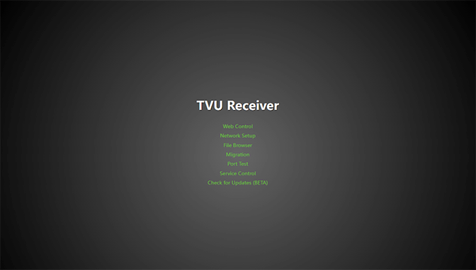
Use the TVU Receiver landing page links to access:
- Web Control – TVU Receiver Web UI.
- Network Setup – Network and DNS setup.
- File Browser – Recorded files and Profile settings.
- Migration – Receiver configuration restoration.
- Port Test – Network diagnostics for inbound/outbound ports and NTP status.
- Service Control – Select Service Control from the receiver landing page to enable FTP, SSH, and Media Server.
- Check for Updates (BETA) – Software updates.
Note: For detailed information about the Port Test tool, refer to Appendix B, “Network diagnostics – Port Test tool.” For detailed information about Service Control, refer to “Service Control featrures.”
Logging in to the TVU server user interface
- Open a Web browser window and enter:
http://external_IP_Address:8288
(Where External_IP_Address is your server’s static IP address)
- The TVU Receiver landing page will display.
Logging in to the TVU server user interface remotely
To log in to the TVU server user interface remotely, have your server’s static IP address available and complete the following steps:
Note: TVU recommends using Google Chrome as your browser.
- Open a Web browser window and enter:
http://external_IP_Address:8288
(Where External_IP_Address is your server’s static IP address)
- The TVU Receiver landing page will display.
TVU Linux Receiver Network Settings
The following instructions describe how to access the Network Setup page, navigate to the Receiver web interface, and return to the Receiver landing page.
Refer to the “TVU Server Hardware User Guide, Models VS3500, VS3550, VS3600, and VS3650 – Linux v8.2” for hardware setup and configuration instructions.
To open the Network Setup screen:
- Click Network Setup on the TVU Receiver landing page. The Receiver Web Control login page displays.
- Enter the following information:
User ID: tvu
Password: Enter the last 8 digits of the PID using all caps.
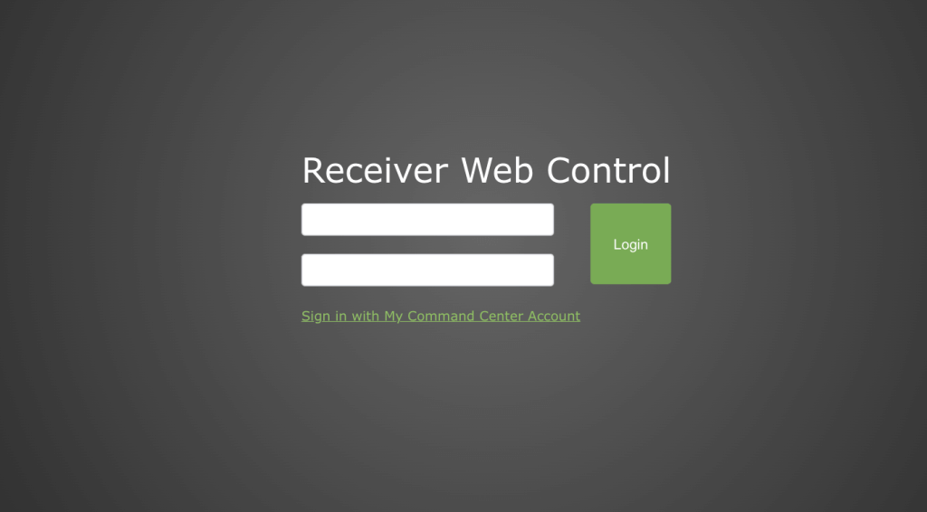
- Click Login.
- The TVU Network Setup window will display.
- To return to the TVU Receiver landing page, click the TVU Logo in the top left corner of the interface.
- To open the TVU Receiver web interface page, click Web Control in the top right navigation panel and select a receiver.

- The TVU Receiver web interface will display.
- To return to the TVU Receiver landing page, click the TVU Logo in the top left corner of the interface.
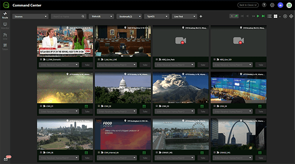
Command Center Web interface features
The TVU server can also use the TVU Command Center Web interface, which provides a cloud-based centralized management and control solution for all TVU devices and services. For detailed information about TVU Command Center, refer to the “TVU Command Center Set up and User Guide.“
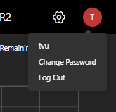
Changing the receiver user password
Note: TVU Networks strongly recommends changing the default password of all devices. Default passwords represent a security risk and should not be used in any situation where devices may be reached remotely.
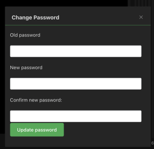
- To change your receiver user password, click the User Preference icon and select Change Password.
- Enter the required field information in the Change Password pop-up window and click Update password.
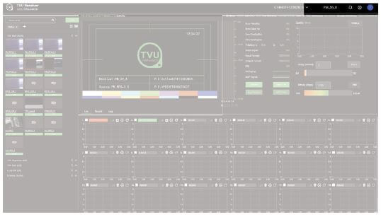
TVU Web user interface overview
The TVU Linux v8.2 software has two primary user interface modes, Live and Record. These operational modes can be accessed by clicking the Live and Record tabs on the top-left side of the Data transmission monitoring panel.
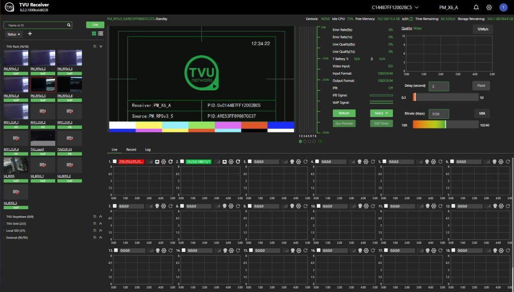
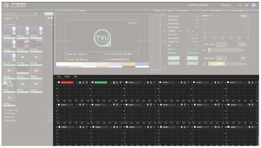
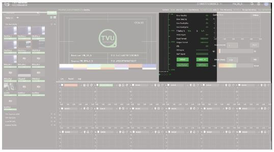
Live viewing mode
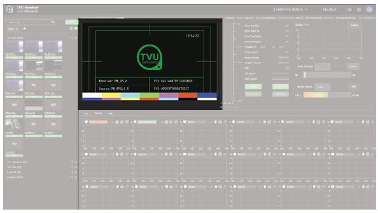
Refer to the following image for the TVU server Live viewing mode controls and functions.
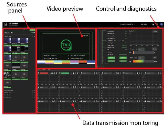
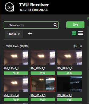
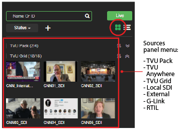
Sources panel
The Sources panel is on the user interface’s left side, as shown below.
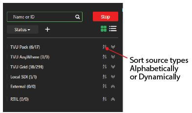
The Sources panel menu alphabetically displays TVU Pack, TVUGrid, Local SDI, TVU Anywhere, External sources, and RTIL in their expandable panels.
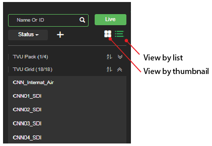
An operator can choose which source types to display in the sources panel. Locate your source type and click the Up or Down arrows to expand or collapse a source type category. Source types can also be viewed by thumbnail or in a list after they are expanded.
Sources within each category can also be arranged alphabetically or dynamically by clicking the sort icon.
The Sources panel also includes the following controls and functions:
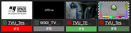
The source thumbnails will display using one of the following status indicators:
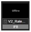
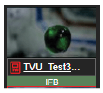
The following thumbnail indicates the video source is Offline.
The following thumbnail indicates that the remote source is powered and connected, but no video input is detected.
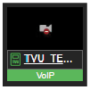
The following thumbnail indicates when a source is online and live video is detected.
The following thumbnail indicates that the video is a generic external source. Other external sources are SMPTE, YouTube, or SRT, with identifying thumbnail icons.

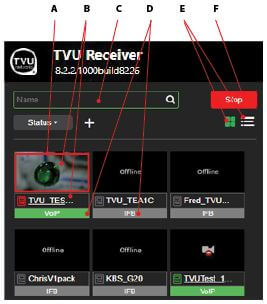
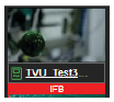
(A) Source video feed thumbnail: When a video or live source is selected, the thumbnail is framed with a red box around the thumbnail image. This thumbnail with a red frame indicates a selected video or live source.
(B) Source information: Mouse over the thumbnail to display the source information. For example, when a transmitter is online, the transmitter’s name will display underlined below the thumbnail. Click the underlined transmitter name to display its physical location and GPS data.

(C) Search bar: Allows the operator to search for available input sources by name.
(D) IFB indicator (VoIP predecessor): The Interruptible Feedback (IFB) feature used in older model transmitters allows your news operations center to speak directly to a TVU transmitter in the field. The IFB option includes a mixer/preamp. The mixer has a USB port for connecting to your server and an XLR and 1/4 in. port for plugging in a microphone.
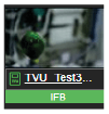
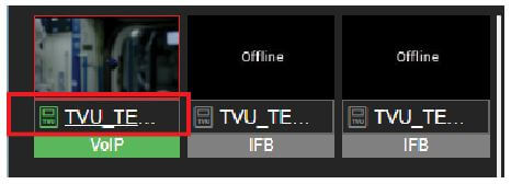
IFB: To turn on IFB, click “IFB” below the thumbnail. When IFB is on, the background color turns red, as shown below.
To turn off IFB, click “IFB” below the thumbnail. When IFB is off, the background color turns green, as shown below.
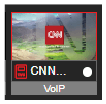
VoIP indicator: The VoIP function provides a two-way, higher-quality communication than IFB. The VoIP function automatically enables when a live transmission is started. When enabled, the VoIP background color turns from green to flashing red to solid red. VoIP has to be disabled by manually pressing the button.
The VoIP/IFB status also displays in the diagnostics “Status” panel on the left side of the interface.
Additionally, if a TVU transmitter has a VoIP or IFB function, both IFB and VoIP will automatically become enabled when going live.
Refer to the “Advanced configuration” section for IFB and VoIP indicator status details.
(E) View by thumbnail or list: The thumbnail and list features allow the operator to view and select sources in the source panel by graphic thumbnail or list.
Note: The source type heading must be expanded using the Up arrow before this feature can be enabled.
An operator can select and display any source by type. Click the following Types drop-down menu below the “Search” bar.
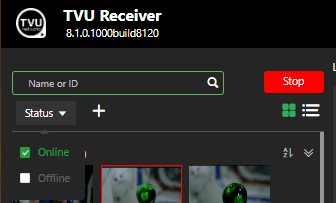
An operator can also choose source types to display by their status by clicking the Status drop-down menu below the “Search” bar.
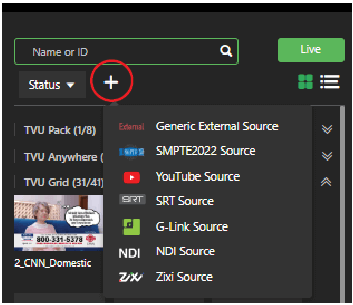
In addition, an operator can choose an external source. Generic External, SMPTE, YouTube, Zixi, and SRT are available as external source selections. These source types are accessed from the “+” menu.
(F) Live/Stop button: The Live/Stop button allows the operator to stop or restart a live transmission from a selected source.
Video preview panel
The video preview panel shows the live video output state or the offline state screens. The preview panel has audio control capability. When a video is live, the operator can mute or unmute the audio to the live video by clicking the speaker icon in the bottom left corner of the preview screen.
Note: The audio button only affects the audio output to your Web browser. It does not affect the SDI output to your server.
When a source is live, the video preview displays in the preview window, and the red stop button displays. To stop the transmission, click the red Stop button.
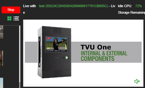
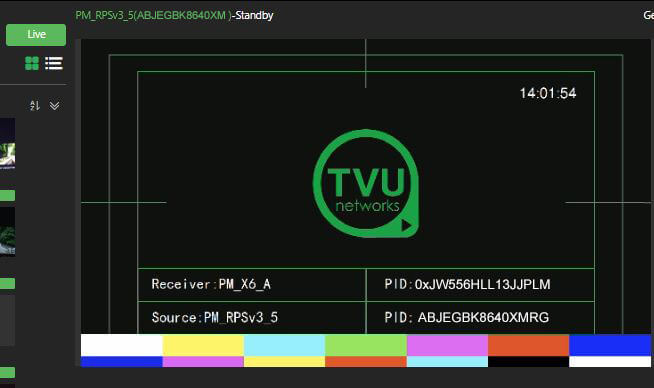
When a source is not live, the video preview displays the following TVU slate, and the green Live button displays.
Data transmission monitor panel
The data transmission monitor panel is located below the preview panel.
The data transmission monitor panel includes the following Live tab controls and functions:
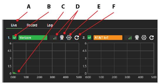
(A) Data transmission monitor panel: The Live tab displays all data connections’ current number and status. The connection status appears as green, red, yellow, or gray.
(B) Check box: A check box and status bar are associated with each card. The check box enables or disables a data connection. If unchecked, it will not be used to pass data. If the box is checked (default), the connection will be used to pass data.
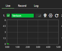
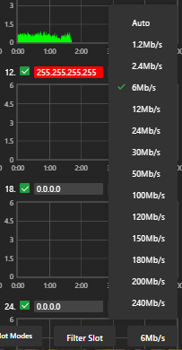
(C) Monitor histogram: Displays status, throughput, and the IP address of each modem.
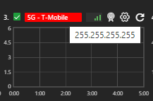
(D) Connection mode and connection strength indicator: The connection mode is displayed next to the connection strength, indicated with three bars.
(E) Configuration menu: Provides access to the user configuration of the selected TVU pack.
(F) Reset: Provides a full-power reset for a modem. This feature is used when the modem can no longer connect or is experiencing a problem. Click the Reset icon to force the modem to power cycle and reset.
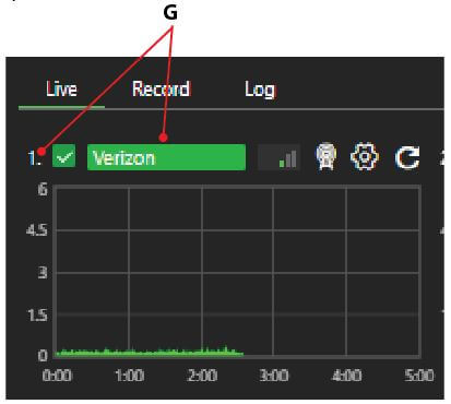
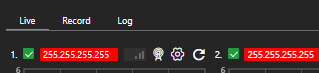
(G) Connection name and status: Individual readout panels show each active card’s carrier name (when available). The slot number of each data card is indicated to the left of the carrier name. To retrieve a data card’s IP address, mouse over that data card’s name. You can enter your preferred name if a name is automatically provided and displayed as <name>. However, this will reset upon reboot.
The color indicators displayed within the carrier name panel indicate the following status:
- Red: Not connected or dialing
- Green: Connected and passing traffic
- Yellow: Connected but not passing traffic
- Gray: Disconnected or unplugged
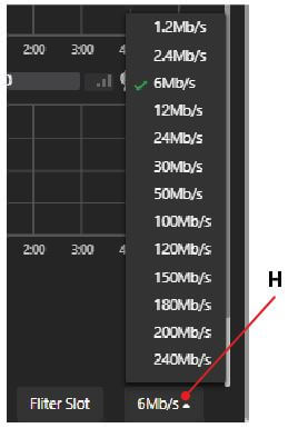
(H) Scale: The Scale drop-down menu allows the operator to set the scale for the histogram. When the scale changes, it will affect all the histograms displayed. Selection settings are 1.2 Mbps, 2.4 Mbps, 6 Mbps, 12 Mbps, 24 Mbps, 30 Mbps, 50 Mbps, 100 Mbps, 120 Mbps, 150 Mbps, 180 Mbps, 200 Mbps, and 240 Mbps.
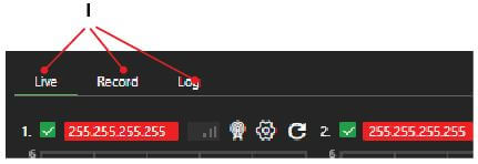
(I) Mode selection and indicator lights: The currently selected mode displays as a green-lighted tab. The modes that can be chosen are:
- Live: The Live mode is the primary interface used during a live transmission. When this tab is selected, the status of each of the data card network connections will be displayed.
- Record: The Record mode displays the store and forward interface for previewing, downloading, and managing TVU Transmitter’s stored footage and files transferred via Auto Sync. Files transferred via FTP can also be accessed via this interface. For more information, refer to “Working with recorded content.”
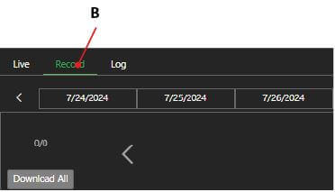
- Log: The Log tab displays information on Operation, SCTE, and Network Connection usage.
Settings panel – Control
The settings panel controls are located below.
The control settings panel includes the following controls and functions:
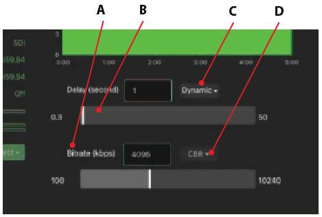
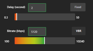
(A) Bitrate control: The TVU server has a smart VBR scaling system. The unit automatically adjusts the bitrate to output the best quality picture based on the desired latency. To effectively take advantage of the smart VBR scaling system, set your desired latency and the maximum bitrate you want to utilize. The bitrate setting for 4K streaming is now supported up to 25 Mbps.
(B) Delay control: To configure the live shot latency, adjust the slider or enter a value manually in the input box and press Save.
This value is always stable and will not change unless manually adjusted during transmission. Delays as low as 0.5 seconds should be routinely achievable in good bandwidth conditions. There is a relationship between lower delay and the amount of bandwidth consumed for error correction, so higher delays of 4 to 10 seconds are recommended for non-latency-sensitive transmissions.
(C) Adaptive delay control (dynamic/fixed) for Grid only: Controls the dynamic buffering feature of Grid. When set to dynamic mode (recommended), the server automatically increases the stream buffer to ensure stable transmission. This selection maximizes stream stability but at the potential cost of increasing the delay/latency. The fixed mode will lock the Grid stream to a specific delay but allow errors if the setting is too aggressive. We recommend using dynamic mode for normal operations. Where fixed mode is enabled, the operator should pay extra attention to the stream stability with their given setting.
(D) VBR/CBR: The TVU server has a smart VBR scaling system.
Refer to Advanced operations for more information.
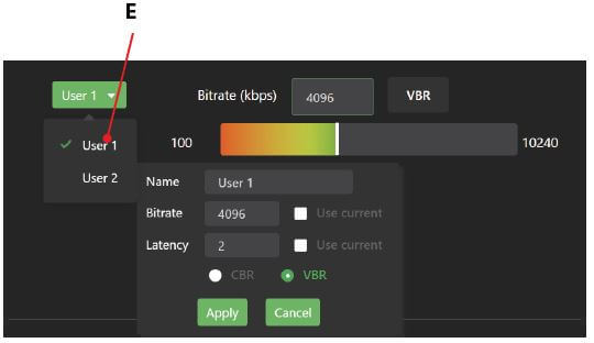
(E) Preset selection menu (operational): Click the Select drop-down menu to view User’s 1 and 2 presets.
- User 1 & User 2: These are user-definable presets. To program these, users right-click the preset they would like to define. Users can then name the preset, change the bitrate, manually set latency, or check Set Current, saving the current latency setting to that preset. Press Apply to program once finished.
Status panel – diagnostics
Many indicators are arranged vertically in the Status panel to help an operator make quality and troubleshooting decisions. Information such as error rate and line quality are displayed, and a quality histogram depicts the total transmission encoding bitrate over a period. The histogram’s scale can be changed by selecting a different display option from the drop-down menu. The status of the transmitter’s batteries is also displayed.
The Status panel diagnostics are located as shown below.
The Status panel includes the following controls and functions:
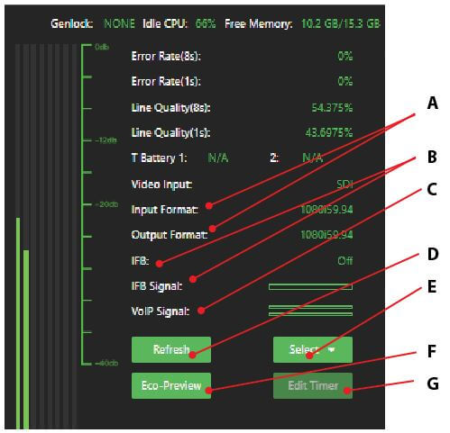
(A) Input and output formats: “Input” displays the transmitter’s video input format. “Output” displays the server output setting.
Note: The server output format follows the input format when the Input Match feature within Feature Control is enabled.
The TVU Pack input and server output should match. The server software is not intended to convert or adjust the resolution. In the event of a mismatch, the server will attempt a format conversion, which may result in losing video quality and removing closed captions from the transmission.
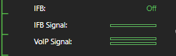
(B) IFB status: The IFB status and the IFB Signal display. The IFB signal has a strength meter that depicts the input level of the IFB.
(C) VoIP status: The VoIP Signal has a strength meter that depicts the input level.
(D) Refresh button: If the video displays as a black screen or pixelates heavily and does not recover automatically within 15 seconds, click the Refresh button to reset the video stream.
(E) Select button: The Select button opens the preset selection drop-down menu.
(F) Eco-Preview: The Economy Preview Timer Setting feature allows the operator to set the preview mode timer (in minutes). The operator can also set the Preview mode to remain, whereby the operator can manually exit.
Note: Refer to the “Advanced configuration” section for more information.
(G) Edit timer: Use the Edit time button to edit the Economy Preview setting.
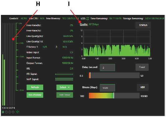
(H) Audio level light display: The audio bars allow users to monitor their audio levels visually. This displays decibels relative to the server’s full-scale (dBFS) audio input level.
(I) Quality histogram/Quality link: The quality histogram below the Quality link displays a 5-minute aggregate histogram of the live transmission.
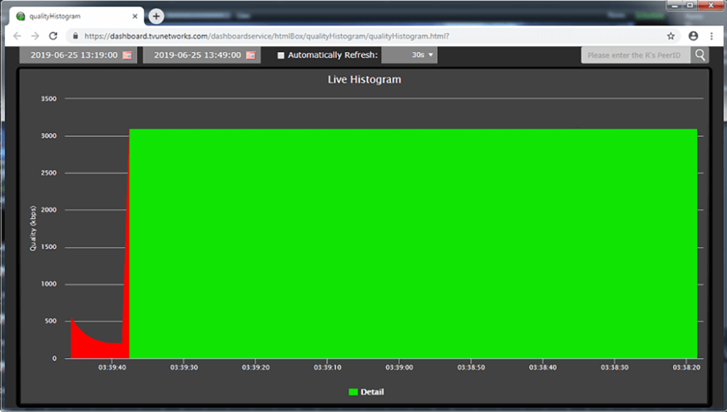
Click the Quality link to access the post-live histogram. The post-live histogram allows users to recall a histogram of a transmission and display it as a Web-based graph. The operator can review the post-live histogram and the overall performance of that transmission over a specific period.
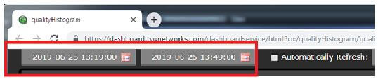
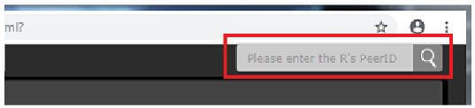
Post-live histogram features: Users can look at a transmission that took place on a specific date and monitor the entirety of a live transmission in a “Post-Live histogram.” The automatic refresh time can be set to a desired length, and users can search for a specific transmitter by typing in the PID number of the transmitter.
Advanced features
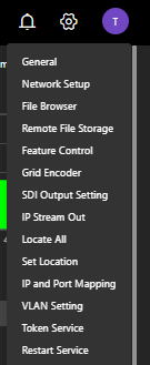
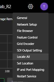
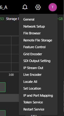
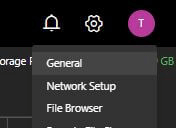
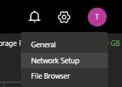
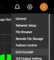
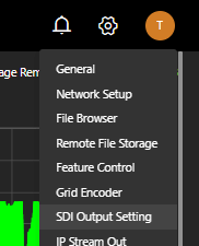
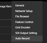
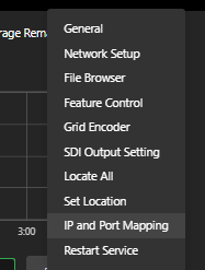
The system settings drop-down menu location is shown below.
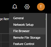
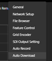
Click the Settings icon in the top right corner of the receiver user interface to open the drop-down menu and select from the enabled features.
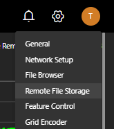
The Settings menu provides easy access from the WebR to the Network setup, File Browser, and Remote File Storage pages without returning to the TVU Receiver landing page.
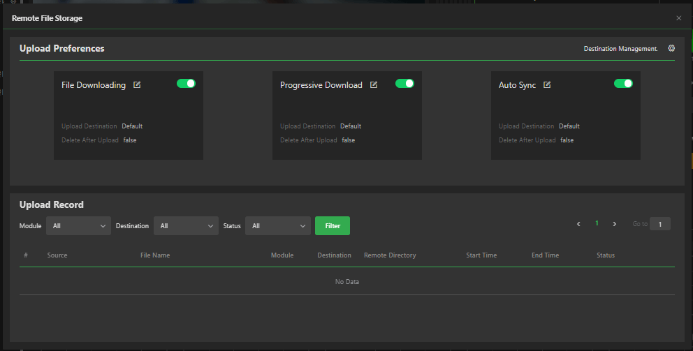
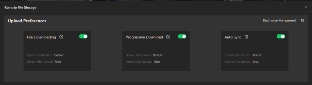
The Remote File Storage feature opens a new pop-up window that displays upload preferences and the upload record list. You can access settings for Auto Sync, file downloading, and progressive downloads in the Upload Preferences panel. Click the Settings icon in the top right panel to access the FTP destination management window to add or delete a new destination.
Choose from a list of system settings from the Settings drop-down menu. The controls and functions in this menu are as follows:
- General
- Time Zone
- Custom NTP Service
- Set Media Device
- Talkback
- VoIP Start with Live
- Prompt a Warning When Stopping a Live Transmission
- Progressive Download
- Default Delay and Bitrate
- External source
- Video feedback
- Switch Live on Hold to Standby
- Custom background logo
- Network setup
- File browser
- Remote File Storage
- Upload Preferences panel: File Downloading, Progressive Download,Auto Sync, and Destination Management configuration
- Destination Management Settings:
- Upload Record panel (list)
- Settings – Profile settings
- Settings – Change password
- Feature Control
- Grid Encoder
- Transcriber
- SDI Output setting
- 3G SDI format settings
- Passthrough Streaming
- Vision Tag
- Auto Record
- IP Stream out
- Encoders 1 – 6 setting
- Audio mapping
- Profile Management
- Live Encoder
- Auto Download
- Locate All
- Set Location
- IP and Port Mapping
- VLAN Setting
- Token Service
- Restart Service
- Vision tag (optional feature)
- Auto Record (optional feature)
Note: Refer to the “Advanced configuration” section for more information about settings selections.
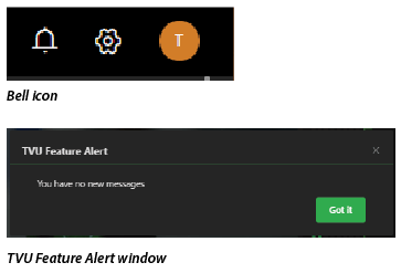
TVU Feature Alert
Click the Bell icon to view new TVU Feature messages.
Advanced operations
TVU Linux server transmission – Going Live
Taking your transmission live involves selecting a source, starting a live session with a video source, setting the correct bitrate and delay, and tuning your shot.
Selecting a source
To select a source from the Web Receiver UI, complete the following steps:
- In the source panel, expand the source type, select thumbnail view, and click on the desired live source thumbnail.
- After a source is selected, a red box will frame the thumbnail image.
Note: Selecting a transmitter that has a video thumbnail (live source), will start a live session.
The source thumbnails will display using one of the following status indicators:
The following thumbnail indicates the video source is Offline.
The following thumbnail indicates that the remote source is powered and connected, but no video input is detected.
The following thumbnail indicates when a source is online and live video is detected.
The following thumbnail indicates that the video is a generic external source. Other external sources are SMPTE2022, YouTube, NDI, or SRT, with identifying thumbnail icons.
- If the live source was previously activated and then stopped, the thumbnail will continue to display with the thumbnail framed in red. To take the source live again, click the Live button.
Taking a shot live
To take the shot live, complete the following steps:
- Click the thumbnail in the source panel to start a live session with a source not already framed with a red box.
- Click the Live button to start a live session with a source framed with a red box.
- Set the bitrate, delay, and VBR/CBR settings.
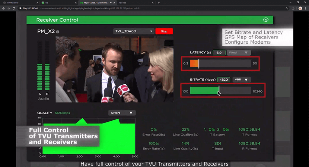
Setting the variable bitrate (VBR) and delay
The two primary controls affecting the quality and latency of a live shot are the bitrate and delay sliders displayed in the Settings control panel.
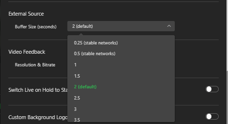
In the Settings > General pop-up window, users can change the default buffer size from the 2-second default to 0.25 – 0.5 seconds for very stable networks. Other delay selections are available from 1 second up to 3.5 seconds.
To set or edit the bitrate and delay, complete the following steps:
- Delay: To configure the live shot latency, adjust the slider, manually enter a value in the input box, and click Apply.
This value is always stable and will not change unless manually adjusted during transmission. Delays as low as 0.5 seconds should be routinely achievable in good bandwidth conditions. There is a relationship between lower delay and the amount of bandwidth consumed for error correction, so higher delays of 4 to 10 seconds are recommended for non-latency-sensitive transmissions.
- Bitrate: Use the slider to select a value, or enter it manually into the input box, and click Apply.
A higher value will increase the pack’s encoding quality and transmission throughput (subject to bandwidth availability) to a maximum threshold of 10 Mbps. Bitrates above 5 Mbps should not be required except for fast or high-motion sports videos.
Note: Changes to the bitrate slider can be made during a live transmission without interrupting the shot. Adjusting the Delay setting during a live transmission will interrupt the video while the stream rebuffers.
- Click Settings and select General. Scroll down to the Default Delay and Bitrate Setting panel. The Default Delay and Bitrate Settings display. The slider must be green “enabled” as shown.

Selecting VBR vs. CBR
The TVU system uses the SmartVBR™ adaptive encoding technology to maximize the reliability of the live transmission. The encoder will detect the bandwidth available and adjust the encoding bitrate to the maximum value set on the slider. If the SmartVBR detects a drop in available bandwidth, the encoding resolution will decrease to keep the video stable and smooth.
Variable bitrate (VBR) mode
VBR is the default setting and should be used under most circumstances. Click the VBR drop-down menu above the bitrate slider to select or change the setting.
Constant bitrate (CBR) mode
In some circumstances, turning off the VBR logic and forcing the transmission to CBR mode may be desirable. The encoding will be locked to the configured bitrate in CBR mode regardless of available bandwidth. The most common application for this setting is with IP satellite systems with fixed bandwidth.
Tuning a shot
In a live interactive environment with ample bandwidth, normal operation would combine a high bitrate with a low delay for smooth, stable transmission. If the bandwidth is constrained and the transmission is not stable at the configured settings, the operator has two primary controls to affect the transmission:
- Increase the delay of the transmission. An increase in delay causes a reduction in the error correction overhead required for stability. A reduction in overhead frees up more available bandwidth for video quality. The delay can be increased from 0.5-second steps up to 10 seconds.
- A stepped increase of 0.5 seconds up to a maximum setting of a 10-second delay should be attempted.
- Suppose the nature of the transmission is especially delay sensitive, or the conditions are very challenging. In that case, bitrate reductions should be performed in steps of approximately 500 Kbps until stability is achieved.
Combining these two controls should allow the operator to routinely and reliably manage video streams from challenging environments.
Note: When transmitting a very low movement or still setting, the pack will adjust and use less data until movement is reintroduced. This is normal behavior.
The Eco Preview – Timer setting feature
The Economy Preview (Eco Preview) saves data usage by reducing the transmission rate to 500 Kbps while in preview mode. The transmission will revert to the previously set bitrate upon expiration or cancellation of the Eco Preview timer.
The Economy Preview button allows the operator to automatically set the Eco Preview mode timer (in minutes) to exit the Preview mode. The operator can also set the Eco Preview mode to remain active, whereby the operator can manually exit.
Note: To display the Eco Preview button, a TVU transmitter must be selected from the source menu.
To set up the Economy Preview Timer feature, complete the following steps:
- In the server information pane, click the Eco Preview button.

The Economy Preview – Timer Setting dialog displays.
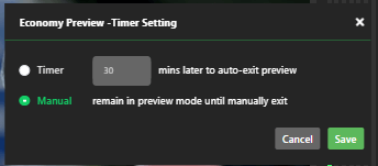
- Select the appropriate radio button, enter the desired Timer value in minutes, or click the Manual setting button.
- Click Save or Cancel. Click the X to exit the dialog. After exiting the dialog, the Eco-Preview button changes to Exit-Preview.

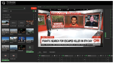
When Eco-Preview is enabled, the preview panel displays an “Economy Preview” overlay in red.
Note: The Preview message is overlaid on the SDI output to warn operators that the mode is active.
- To exit the preview, click the Exit-Preview button.
GPS Pack locator
The transmitter’s name will be underlined underneath its thumbnail image when it is online.
- Click the underlined name of the transmitter. Then, the GPS data for the transmitter displays.
- To locate all online transmitters, click the Settings drop-down menu and select Locate All.
The GPS location pop-up displays.
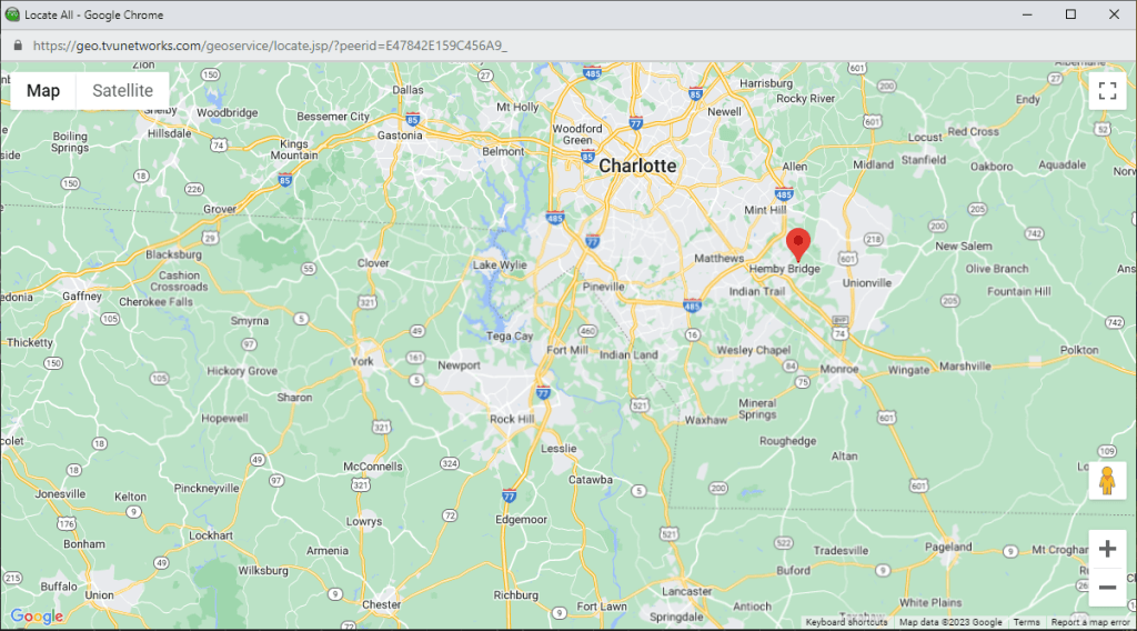
Use your mouse to hover over the location pin to display the TVU Packs’ PID.
GPS Pack recorded content tracking
Additionally, the path is recorded as the transmitter moves to another location. The TVU location pop-up dialog displays the path to easily identify recorded content based on location.
To view the recorded content tracking map, click the Record tab in the data transmission monitor panel first, then click the name of the transmitter thumbnail.
Mouse over a section of the tracked path, and a thumbnail image of the recorded content at that location displays.
Note: If there is no real-time GPS data for a TVU transmitter, cache GPS data will be used for that TVU transmitter and the location pin displays red.
IFB indicator feature
The Interruptible Feedback (IFB) feature (used with early model transmitters) allows your news operations center to speak directly to a TVU transmitter in the field without needing telephone contact. The IFB option includes a mixer/preamp. The mixer has a USB port for connecting to your server, an XLR, and 1/4-inch ports for plugging in a microphone.
On the TVU transmitter, connect a standard set of headphones to the 3.5 mm audio jack on the unit.
To use the IFB feature, click the IFB indicator until it turns red. The IFB on/off status is also indicated in the “Status” panel on the right side of the interface. Additionally, if a TVU transmitter has an IFB function, the IFB is automatically turned on when that transmitter goes live. Once the live transmission is stopped, the IFB function is turned off.
The five indicator colors displayed in “IFB indicators” are defined as follows:
- Red: The IFB function is in use.
- Green: The IFB function is available but not in use.
- Dark Green: Either the transmitter is live with another server or using the IFB function with another server.
- Gray: The IFB Function is not available for this transmitter.
VoIP indicator feature
VoIP indicator: The VoIP function provides a two-way, higher-quality communication than IFB. Click the VoIP indicator under the live preview to use the VoIP function. When enabled, the VoIP background color turns from green to flashing red to solid red. VoIP is automatically enabled when starting a live transmission and disabled manually by pressing the button.
Note: For VS3500/VS3550 hardware models, an external audio box is required to support XLR audio input/output.
Note: The VoIP/IFB status also displays in the diagnostics “Status” panel on the right side of the interface.
Additionally, if a TVU transmitter has a VoIP or IFB function, both IFB and VoIP will automatically become enabled when going live.
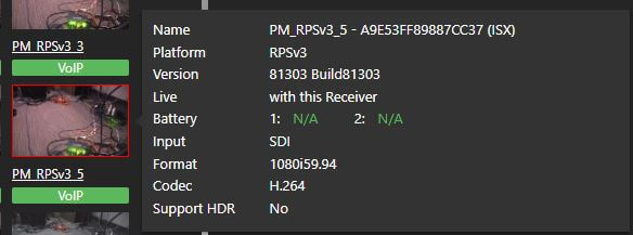
Advanced Inverse StatMux technology – ISX
ISX is an advanced version of TVU Networks’ Inverse StatMux technology. With superior forward error correction technology, ISX also has a higher throughput than the standard Inverse StatMux under the same conditions. Additionally, with ISX, file transfers are between 2x and 4x faster than standard Inverse StatMux. This solution enables TVU transmitters to deliver resilient, HD, professional broadcast-quality pictures in even the most challenging wireless environments.
Once ISX has been installed on a TVU transmitter, “(ISX)” will appear at the end of the PID Name when you mouse over the source thumbnail, as shown in “ISX location” below.
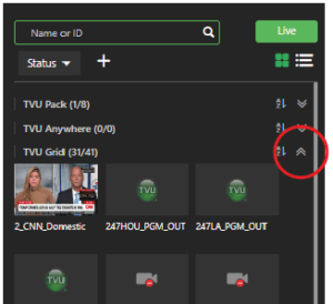
TVU Grid source
Expand the TVU Grid list by clicking the double arrows to view the available Grid sources.
Adding an external source
To add an external source to the server Web UI, complete the following steps:
- Click the plus + icon next to the Status drop-down menu. The external source pop-up window displays.
- Select an external source from the pop-up window to be added. The four supported formats are:
- Generic External Source
- SMPTE2022 Source
- YouTube Source
- SRT Source
- G-Link Source
- NDI Source
- Zixi Source
- A pop-up window displays for each external selection. Enter the appropriate information as follows:
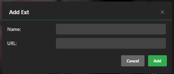
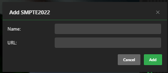
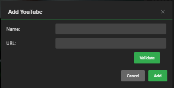
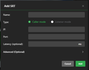
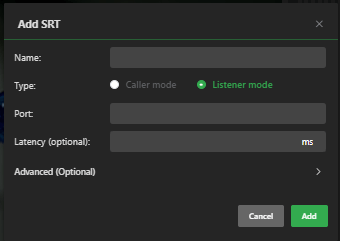
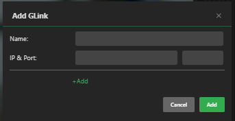
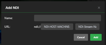
- Name the source and click Add. A thumbnail icon of the added source will display as a selection in the source menu.
Working with data cards
The data transmission monitor panel has two tabs, Live and Record, as shown below.
In the Live tab, the checkbox associated with each data connection status bar enables or disables the data connection. The box is enabled (checked) by default.
- Click the checkbox to select and use the data connection. If the box is unchecked, the card will not pass data.
Note: When a data card is installed, the carrier name along with the slot number displays next to the checkbox.
- To change the scale of the modem histogram, click the bottom right button to display the selection menu. Then, click to select a desired maximum value.
Note: Changing the value will affect all modem histograms.
- To retrieve the IP address of a data card, mouse over the name of the data card field.
- If there appears to be no name associated with the card, you can enter your name, which is displayed as <Name>.
Note: The name change will reset itself upon a reboot.
The color indicators displayed within the carrier name panel indicate the following status:
- Red: Not connected, but dialing
- Green: Connected and passing traffic
- Yellow: Connected, but not passing traffic
- Gray: Disconnected or unplugged
Manual modem configuration
To manually configure a transmitter modem, complete the following steps:
- In the source panel, click the desired source thumbnail. When selected, the source is framed with a red box.
- To configure the modem, click the Gear icon above the source histogram.
- The Gear Icon opens the pack’s advanced configuration menu. Tap the Modem icon.
- The Modems panel is displayed.
- Perform the desired configuration settings.
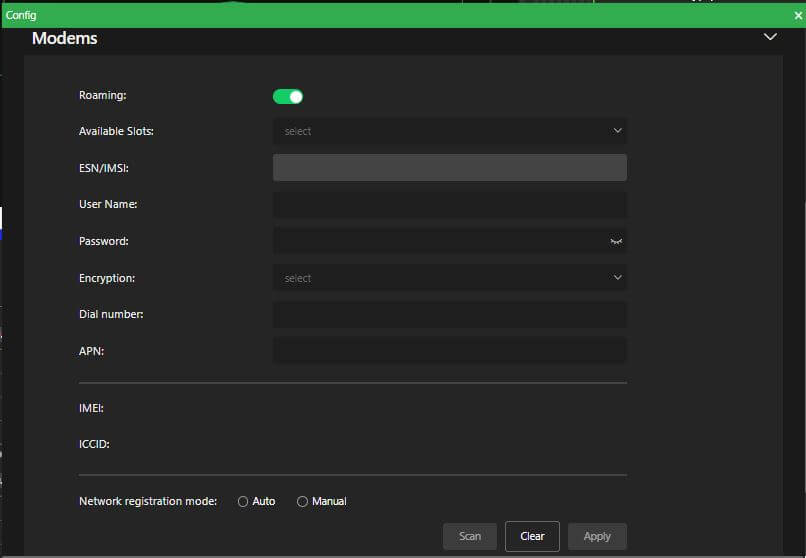
- To save your configuration changes, click Apply.
Manual carrier selection when roaming
To manually select which carrier a modem will roam on, complete the following steps:
- Move the Roaming slider at the top of the Modems panel to the right until green.
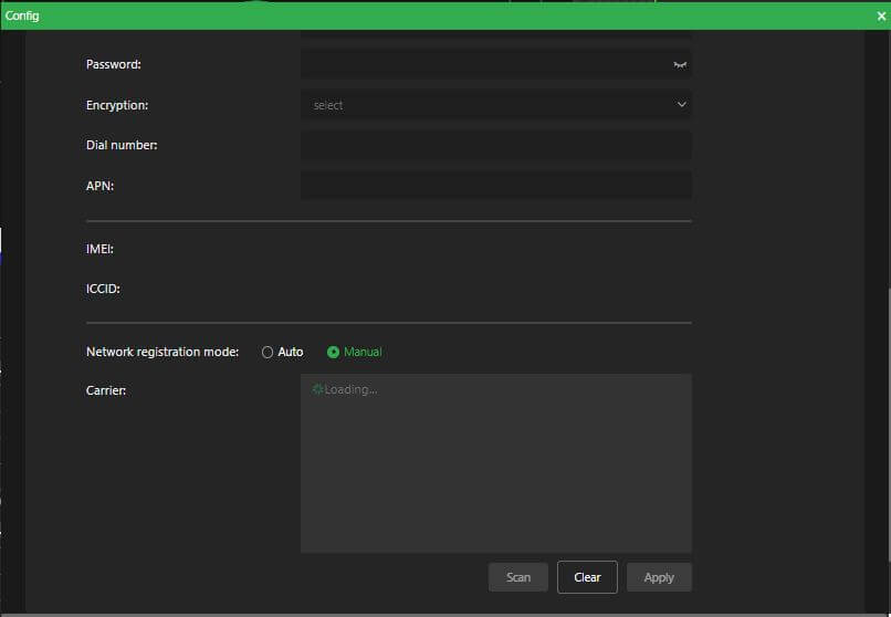
- Click the Manual radio button at the bottom of the Modems panel.
- Click the Scan button. The roaming modem will automatically generate a list of available carriers.
- Click to select a desired Carrier from the Carrier list, then click Apply to confirm your selection.
Advanced configuration and settings
This topic explains how to access and apply advanced configuration and settings.
TVU Linux server settings
The Settings drop-down menu displays default and enabled feature configuration settings selections:
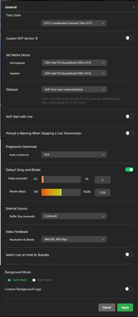
Settings – General panel
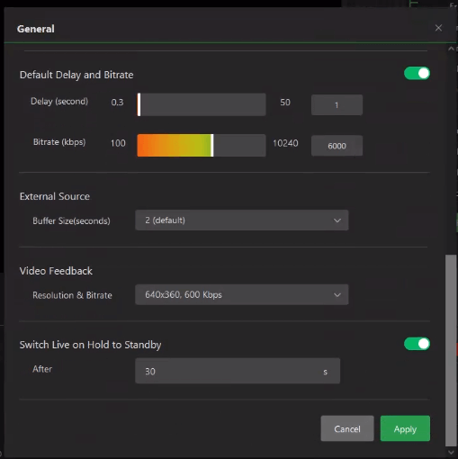
The General Settings panel allows users to:
- Set the Time Zone.
- Enable Custom NPT Service.
- Set Media Device i.e. Microphone and Speaker.
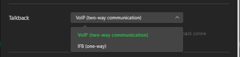
- Use the Talkback feature for (IFB) one-way, or (VoIP) for two-way communication.
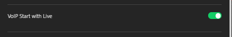
- Enable VoIP Start with Live.
- Enable the Prompt a Warning when Stopping a Live Transmission feature.
- Select a Progressive Download automatic file format conversion.
- Enable and set a Default Delay and Bitrate.
- Choose an External Source buffer size (Network dependent).
- Choose a Video Feedback resolution and bitrate.
- Enable the Switch Live on Hold to Standby feature.
- Change the Background to dark or light mode or enable a Custom Background Logo.
General – Time Zone Setting
The Time Zone feature allows users to set the appropriate UTC zone for their location.
To set the UTC zone for your location:
- Click Settings and select General.

- Scroll to Time Zone Setting.
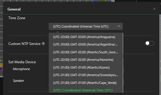
- Select the appropriate UTC from the drop-down menu. Then, click Apply.
General – Custom NTP Service
For details about enabling NTP Custom Service, refer to “Network diagnostics and port testing”, “Adding a custom NTP service.”
General – Set Media Device
The Set Media Device function is used for VoIP/IFB. In the case of a dual-output server, multiple microphone devices and speakers might be available in the system. The Set Media settings allow the operator to assign a device to a specific server. In addition, users can select the No Audio Mix checkbox to enable audio channels to be independent from each other.
To open the Set Media Device panel:
- Click Settings and select General.
- Scroll down to Set Media Device.
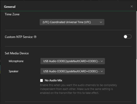
- Make your Microphone and Speaker selections from the drop-down menus.
- Click the No Audio Mix checkbox. If you want to enable the audio channels to be completely independent from each other, then click Apply.
Note: Make sure the No Audio Mix feature is also enabled on the transmitter for this to take effect.
General – Talkback
To choose either one-way (IFB) or two-way VoIP communication:
Scroll down the General panel to Talkback and select from the drop-down menu.
Note: if the transmitter accepts IFB only, then the Talkback connection would still be IFB in this mode.
General – VoIP Start with Live
Enable the VoIP Start with Live feature to stream audio and video when going live. For setup information, refer to “How to set up IFB and VoIP on a TVU receiver.”
To enable this feature:
- Click Settings and select General.
- Scroll down the General panel to VoIP Start with Live.
- Enable the VoIP Start with Live slider.
General – Warning Prompt when Stopping Live
To enable a notification when stopping a live transmission:
Enable the Prompt a Warning When Stopping a Live Transmission slider.
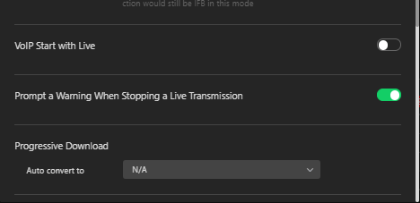
General – Progressive Download
If the TVU server is available, a TVU transmitter can automatically trigger the immediate upload of a high-resolution mirror image of a clip from its SSD to the TVU server by pressing the camcorder’s record button. The Progressive Download format is selected in the Progressive Download Auto convert to drop-down menu. The TVU server will display the download process.
To use the Progressive Download Auto convert to feature:
- Click Settings and select General.
- Scroll down to Progressive Download.
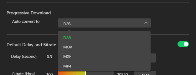
- Click the Auto convert to drop-down menu to select from three conversion options for the mirror image.
- When finished, click Apply.
General – Default Delay and Bitrate
Enabling the slider allows users to adjust the delay and bitrate settings.
To set the default delay and bitrate settings:
- Click Settings and select General.
- Enable the Default Delay and Bitrate sliders. Click and drag the Delay and Bitrate bars to the desired settings, then click Apply.
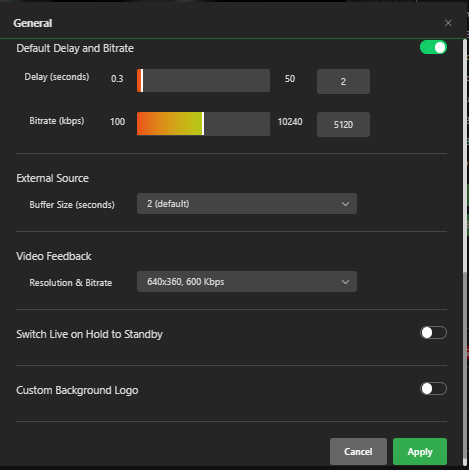
- For information about delay and bitrate settings, refer to Advanced operations “Setting the variable bitrate (VBR) and delay.”
General – External Source
The External Source panel allows users to select a decoding buffer size for their external source.
To select a decoding buffer size:
- Click Settings and select General.
- Scroll to External Source, click the drop-down menu, and select a Buffer size for your external source.
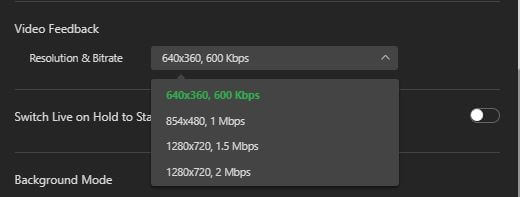
General – Video Feedback
The Video Feedback setting allows users to set a feedback resolution and bitrate.
To select a Video Feedback and Bitrate:
- Click Settings and select General.
- Scroll down to the Video Feedback panel and select a video and feedback from the drop-down menu.
General – Switch Live on Hold to Standby
Users can enable the “Switch Live on Hold to Standby” feature if a live TVU Pack session is interrupted at the source by either powering down the source or loss of video, the TVU Transceiver will keep the session active until the source returns.
The switch to standby timer will release the session after a user-defined interval, making the receiver available for other transmission sources.
To enable the Switch Live on Hold to Standby feature:
- Click Settings and select General.
- Scroll down to the Switch Live on Hold to Standby panel and enable the slider.
- Make a Timer selection from the drop-down menu, then click Apply.
General – Background mode
The Background mode feature allows users to change the user interface background to Dark or Light mode.
To change the background mode:
- Click Settings and select General.
- Scroll down to Background Mode, make your selection, and click Apply.
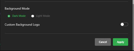
General – Custom Background logo
The Custom background logo feature enables users to display their custom logo in the preview window.
To add a custom background logo: enable the Custom Background Logo slider, and click the Plus “+” box to add a logo (png format only), then click Apply.
- Scroll down to the bottom of the General panel.
- Enable the Custom Background Logo slider.
- Click the Plus “+” box to add a logo (in PNG format only), then click Apply.
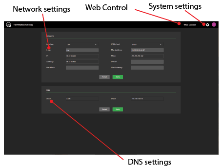
Settings – Network Setup
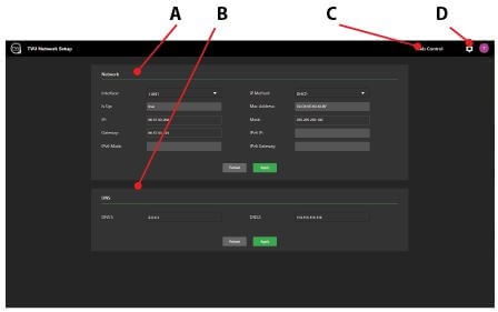
The Network Setup window displays the Basic Network IP and port mapping settings and contains the following configurable panels and controls:
(A) Network settings
(B) DNS settings
(C) Web control
(D) Systems setting menu – Restart service, Factory reset, Restart system, Update firmware, and Shut down.
To open the Network Setup window:
- Click Settings and select Network Setup.
- The TVU Network Setup window displays.
For IPv6 configuration support:
- Enter the IPv6 IP, IPv6 Mask, and IPv6 Gateway.
- Click Apply.
- Click Web Control to return to the Receiver Web interface.
Settings – File Browser
The File Browser feature allows users to access downloaded content from the local storage directory. The details of this feature are further explained in “Accessing downloaded files from the local storage directory.”
To access the File browser feature:
- Click Settings and select File Browser.
- You may also access the File Browser from the TVU Receiver landing page.
Settings – Remote File Storage
Click Settings and select Remote File Storage to open the Upload Preferences and Destination Management functions. Use the Remote File Storage to push downloaded files to external FTP servers. The details of this feature are further explained in “Remote File Storage service.”
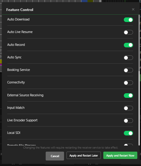
Settings – Feature Control
Many features in the Feature Control menu must be enabled before they can be used.
To access the Feature Control menu:
- To open the Feature Control settings dialog, click Settings and select Feature Control.
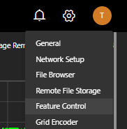
- The Feature Control menu will display.
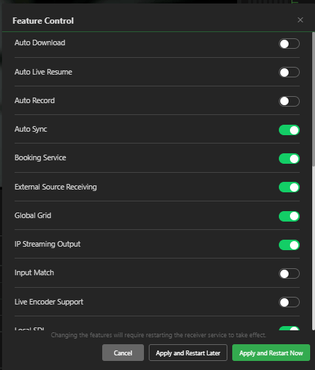
- Click the slider to the right to enable a feature. Click the slider to the left to disable a feature.
- Click the Apply and Restart Later or Apply and Restart Now button for the server software changes to take place.
Feature Control settings are as follows. These features may be enabled or disabled in the Feature Control dialog:
- Auto Download: Enable the Auto Download feature if you want a live session to be automatically downloaded after the session stops.
- Auto Live Resume: This feature will automatically resume the last live source if the server shuts down.
- Auto Record: When Auto Record is enabled, live transmissions from the server are recorded to local storage.
- Auto Sync: Auto Sync is a high-speed file transfer feature that automatically pushes the files from the transmitter to the server using ISX.
- There are two Auto Sync methods you can use to send files to the TVU server automatically:
- You can perform Auto Sync by inserting a USB stick into the transmitter.
- You can use the TVU transmitter wireless hotspot feature to transfer files directly to the TVU transmitter for upload.
- There are two Auto Sync methods you can use to send files to the TVU server automatically:
- Booking Service: The Booking service enables an operator to preset a specific time for a source to go live.
- Connectivity: Enable the Connectivity feature to switch the service region from the Device Config service. Generally, it will be used for Chinese users or someone using a private deployment.
- External Source Receiving: This feature allows the operator to connect to external video sources, including YouTube, through an IP address or URL.
- Global Grid: The Global Grid feature enables Global Grid source pairing.
- IP Streaming Output: The live video transmission is encoded into an IP format and can be sent to six different remote locations.
- Input match: The server SDI output will be converted to match the source input resolution setting.
- Live Encoder Support: The Live Encoder support controls one function.
- Enabling the operation of the Command Center Share function when used in conjunction with a social media account.
- Local SDI: The operator can view SDI input as a local source.
- Remote Commentator feature: This feature is necessary when using the TVU receiver with TVU Remote Commentator.
- TVU Transcriber: TVU Transcriber is a real-time speech-to-text transcribing service. For detailed information, refer to the TVU Transcriber Feature Guide.
- Remote File Storage: Use the Remote File Storage to push downloaded files to external FTP servers.
- SDI to IP: Enables an SDI input for IP streaming output.
- TVU G-Link: The TVU G-Link software feature is an Internet-based, licensed solution for point-to-point live transmission that provides an affordable way for sharing live video between two locations. Enabling the G-Link software feature allows a receiver to transmit video to and from another G-Link receiver (point-to-point) for bidirectional transmission. The TVU G-Link software feature is added to the existing VS3100, VS3200, VS3500, and VS3600 server Web interface and is accessed and enabled in the Feature Control menu.. Refer to the TVU G-Link Software Quick Start User Guide for detailed information.
- TVUGrid Encoder: Enable the encoding of a TVU pack or local SDI stream to Grid.
- TVUGrid Receiving: This feature is necessary to receive a G-Link transmission from an encoder.
- TVUMe Receiving: TVUMe allows news organizations to connect with video content providers and freelancers worldwide to exchange live and recorded content.
- TVUPack Receiving: Enable TVUPack Receiving to allow the encoding of the pack stream or local SDI stream to Grid.
- Time Lock: The Time Lock feature enables multiple TVU One’s to synchronize with other receivers at the same set latency.
- Token service: Use the Token service feature to create a new Token, set a Token, and check Token information.
- VLAN Setting: The VLAN Setting feature allows users to set up a VLAN client and server.
- Video Feedback: Enables the remote video feedback function, encoding content at the server and sending it to field equipment for remote monitoring. Users can choose various resolutions and bitrates for return video feeds up to 720p, 2 Mbps. The Video Feedback setting allows users to set the buffer for ingesting external sources as low as 0.25s under a stable network.
- Vision Tag: Used to enable/disable live MediaMind AI facial and location recognition.
- Web File Support: Enables ENPS integration functions.
- VoIP Start with Live: Enable the VoIP Start with Live feature to stream audio and video when going live.
- Default Delay and Bitrate Setting: Enabling this feature allows users to adjust the settings.
- Restart Service: The Restart Service feature can now be accessed in the Settings drop-down menu to reset the WebR after enabling or disabling features.
- Set Location: Select Global and China connectivity settings for your remote location. Caution: Select China only if your receiver location is in China.
- Time Zone Setting: The Time Zone feature allows users to set the appropriate UTC time zone.
- Service Control: Select Service Control from the receiver landing page to enable FTP, SSH, and Media Server.
Settings – Grid Encoder
The Grid Encoder feature enables encoding a TVU Pack or local stream to TVU Grid. This feature must be enabled in the Feature Control window before it can be used.
To encode a pack or local stream to TVU Grid:
- Click the Settings menu and select Grid Encoder.
- The Grid Encoder window will display.
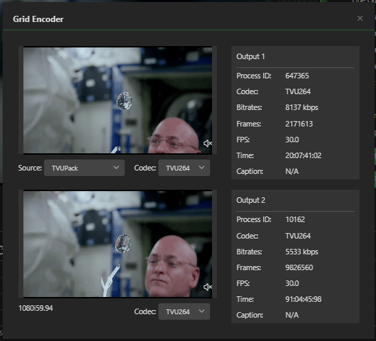
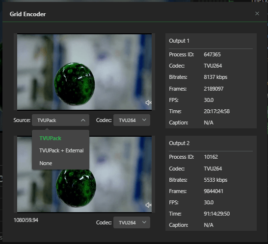
- Click the Source drop-down menu to select which source type you want to be available on output 1.
You can choose from a TVU Pack, TVU Pack and External, or select None to disable output 1.
Note: Output 2 will always use the SDI input as its source.
- Select a Codec from the Codec drop-down menu.
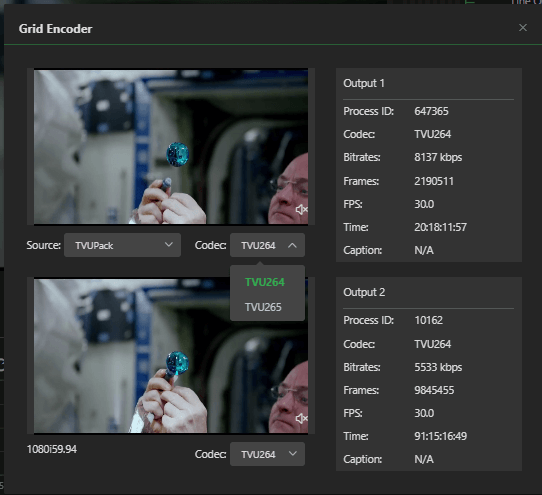
- Close the window when finished.
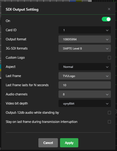
Settings – SDI Output Setting
SDI settings can be configured for single or dual-output servers.
To choose an SDI Output Setting:
- Click Settings and select SDI Output Setting.
- The SDI Output Setting window will display.
- Enable the On slider.
Note: The following figure shows the standard configuration of the output ports on a dual channel receiver.
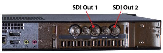
Refer to “Dual output server configurations.”
SDI Output settings:
- Output Format: Use the Output format drop-down menu to select a resolution for your video output.
- 3G-SDI formats: Supports 3G SMPTE level A and SMPTE level B card formats.
- Last Frame: Select Logo from the Last Frame drop-down to output the TVU slate screen. Select Last Frame to repeat the last frame or select Black for no image.
- Last Frame lasts for N seconds: Enter a value for the “Last Frame” selection to display.
- Audio Channels: Use the Audio Channels drop-down to select 2, 8, or 16 audio channels.
- Output -12 db audio while standing by (checkbox): Click the check box to enable a -12 db audio output along with the TVU slate. When the box is unchecked, the -12 db audio output is disabled, and only the TVU slate is enabled.
- Stay on last frame during transmission interruption (checkbox): Click this checkbox to enable the “Last Frame” and “Last Frame to last for N seconds” settings in the event of a transmission interruption.
Note: In the event of any changes made to the SDI Output setting dialog, you are prompted to restart the server for settings to take effect.
Dual-output server configurations
With a dual-server configuration, an operator can access each server by completing the following steps:
- Click the server PID drop-down menu and select a server from the list.
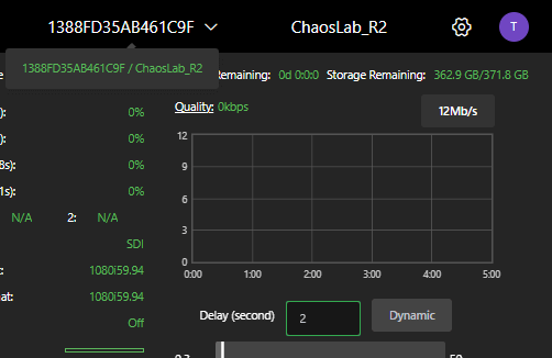
- The login screen opens. Log in to the TVU Receiver Web Control user interface.
Settings – Passthrough Streaming
The Passthrough Streaming feature allows high-quality CBR video from the TVU Pack to be transmitted to the receiver and converted to IP without transcoding. Note that this feature needs to be specially authorized on the receiver, and an extra charge may apply.
- Click Settings and select Passthrough Streaming.
- Select the SRT or UDP protocol.
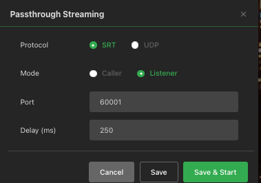
- Select the Mode and click Save and Start.
Settings – Transcriber
TVU Transcriber uses AI technology to convert speech into text from a live audio input source. This text will be output as closed captions and a text file and output on your SDI or IP output stream for monitoring purposes.
The Feature Management menu allows an operator to enable the TVU Transcriber option. Refer to the “TVU Transcriber Feature guide” for detailed information about setup and usage.
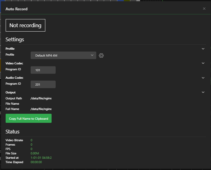
Settings – Auto Record
The Auto record feature lets users record live transmissions from the server to local storage.
The Auto Record feature must be enabled in Feature Control before it can be selected.
To enable the Auto Record feature:
- Click Settings and select Feature Control.
- The Feature Control settings menu will display.
- Slide the Auto Record switch to the right until it turns green. Click Apply and Restart Later or Apply and Restart Service, then close the window.
- Click Confirm to restart the service.
- To ensure that Auto download has been enabled, click Settings. The Auto download displays as a Feature selection.
To use the Auto Record feature:
- Click Settings and select Auto Record.
- The Auto Record window will open.
- Select a Profile from the drop-down menu.
Settings – Auto Download
To enable the Auto Download feature:
- Click Settings and select Feature Control.
- The Feature Control settings menu will display.
- Slide the Auto Download switch to the right until it turns green. Click Apply and Restart Later or Apply and Restart Service, then close the window.

- Click Confirm to restart the service.
- To ensure that Auto download has been enabled, click Settings. The Auto download displays as a selection. Click Auto download.
- The Auto Download pop-up will display.
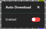
- Enable Auto Download and close the pop-up window.
Settings – IP Stream Out
The optional IP Stream Out feature allows users to take a live TVU transmission and easily output it to a third-party file storage folder, or website, such as YouTube. The live video transmission is encoded and can be sent to a maximum of nine different remote locations (Formats are: File, RTMP(s) HLS, HLS Push, UDP, RTSP, SRT, Zixi, and NDI). In addition, the user can add their logo to the IP streaming output. A maximum of six output selections can be configured at the same time.
Note: The default is one encoder to purchase additional encoders, contact TVU Sales.
- If the IP Stream Out feature is enabled, click the Settings drop-down menu and select IP Stream Out.

- The IP Stream Out window will display.
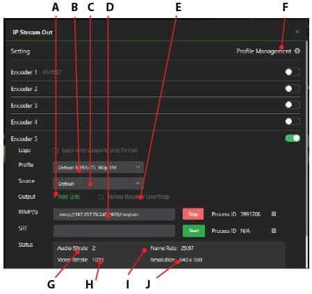
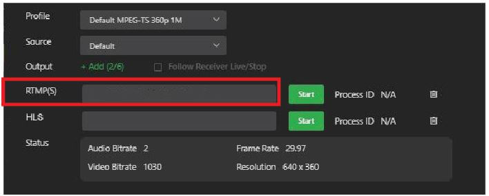
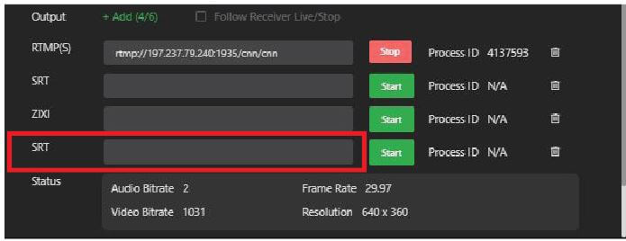
When an Encoder is enabled, the IP Streaming Output options display the following features and functions:
(A) Video stream output menu
(B) Profile- Supports 4K IP stream output
(C) Source
(D) IP output URL
(E) Follow Receiver Live/Stop – Output follows the receiver’s live/stop progress during IP streaming. Check the box to enable.
(F) Profile Management
(G) Audio encoding bitrate
(H) Video bitrate
(I) Frame rate
(J) Resolution
- In the IP Stream Out window, click the Delete icon to remove an existing output from the list. Select a Profile from the Profile drop-down menu and click the Start button to start an output.
- To add a new output, click +Add, then make a selection from the drop-down menu and enter the output URL.
- Click the Profile Management gear to open the Profile window. A user can Delete or Edit an existing preset profile from the list or +Add and save a custom profile setting.
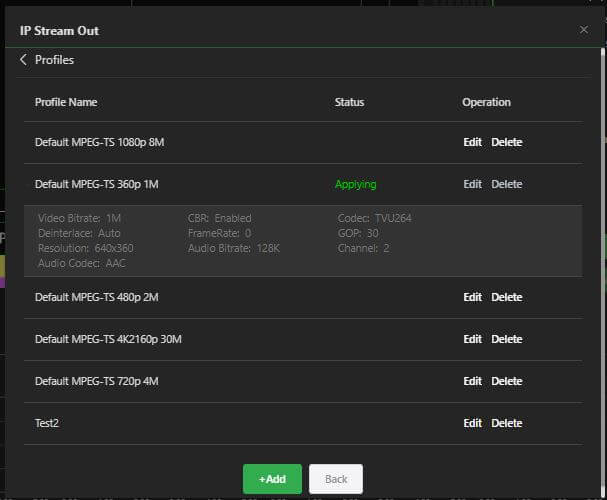
- To add and save a new Profile setting, click +Add. The IP Streaming Out “Add” profile window displays with the following settings:
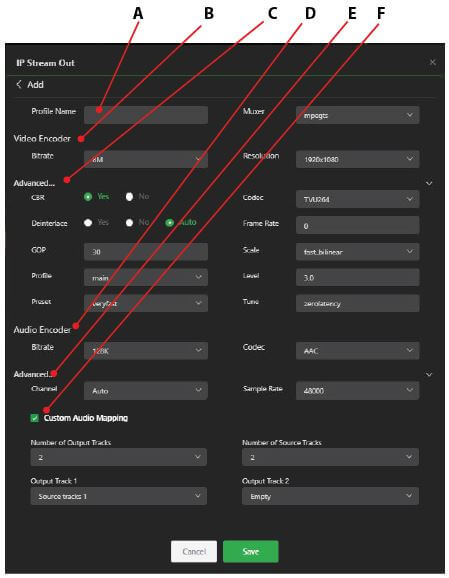
(A) Profile name
(B) Video Encoder settings: Bitrate and Resolution
(C) Audio Encoder settings: Bitrate and Codec
(D) Advanced Video and Audio settings (expand menu for more settings)
(E) Advanced Channel settings: Stereo and Sample Rate
(F) Custom Audio Mapping
- Enter a profile name and select your profile settings. Then, click Save.
- Your new profile is displayed in the Profile drop-down menu as a selection. To edit a profile, click the Profile Management > Edit icon. Make the desired changes and click Save.
Video stream URL format and examples
The IP Stream Output menu includes FILE, RTMP(S), HLS, HLS Push, UDP, RTSP video stream format, Zixi, SRT, and NDI IP output URL selections.
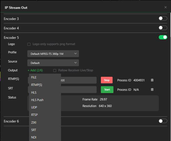
FILE – To Access and record a file using the File Browser Web Interface:
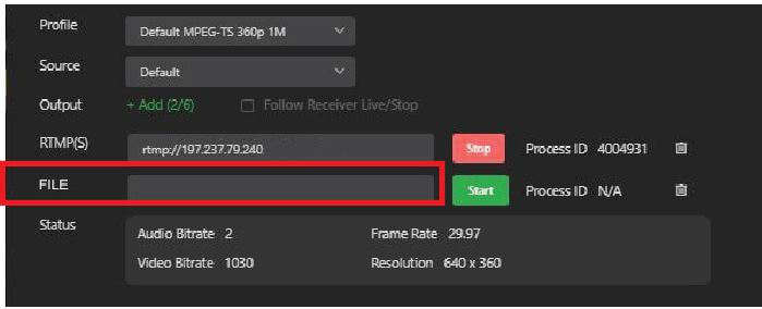
- In the IP Stream window Output section, click +Add and select FILE from the drop-down menu.
- In the FILE field, enter the filename.3.ts.
For example, input “filename.3.ts” as shown below.
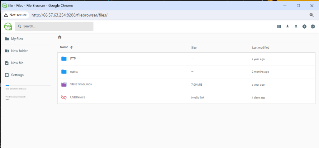
The file is displayed in the File Browser data file root directory. To view the directory:
- Click Settings and select File Browser from the menu.
- If the File Browser login window opens, log in with your TVU Receiver User ID and Password.
RTMP(S) – The RTMP(S) streaming protocol allows you to stream live securely by encrypting the stream between the encoder and the CDN. To use secure live streaming with RTMPS, the CDN location you’re streaming to must support it.
If a CDN provides a stream key:
- In the IP Stream window, click +Add and select RTMP(S) from the drop-down menu.
- In the RTMP(S) field, add the stream key after the URL with a forward slash.
Example: rtmps://1.10378966.fme.ustream.tv/ustreamVideo/10378966:VHgEzINxjh07XTTVt6iIXKQlY3aTMPEI
HLS Push – Enter the destination URL address instead of the host-based URL.
HLS – HLS files (.m3u8 index and .ts clips) are provided in the Web Browser root directory in the nginx > File folder > target File folder.
To output an HLS file:
- In the IP Stream window, click +Add and select HLS from the drop-down menu.
- In the HLS field, enter the file name you want to use.
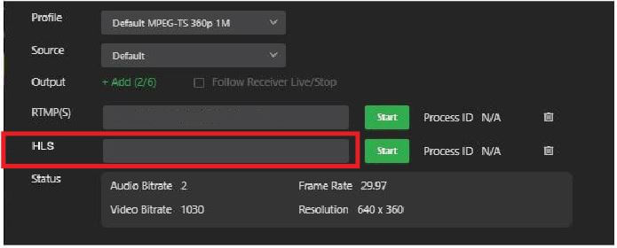
For example, you can access and play this m3u8 file through the URL “http://IP Address/filename.m3u8” using VLC or with other compatible players. The example below shows a file playing with a Chrome plug-in.
The HLS files can also be renamed through the File Browser Web interface by completing the following steps:
- Click Settings > File Browser > nginx > File folder and navigate to the target folder. Select one file in the folder and click the pen icon in the top right corner as shown below.
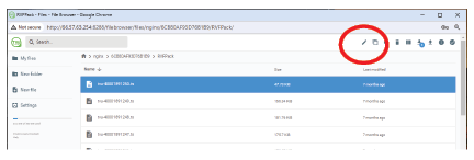
The Rename pop-up window opens.
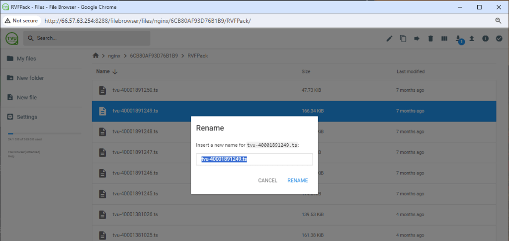
Note: You can also choose the file and press F2 on your keyboard as a shortcut.
- Enter a new name for the file and click Rename.
Note: If a file cannot be renamed, please check if it is being used by some process.
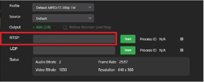
RTSP – If a CDN provides a stream key:
- In the IP Stream window Output section, click +Add and select RTSP from the drop-down menu.
- In the RTSP field, add the stream key after the URL with a forward slash.
Example: rtsp://1.10378966.fme.ustream.tv/ustreamVideo/10378966:VHgEzINxjh07XTTVt6iIXKQlY3aTMPEI
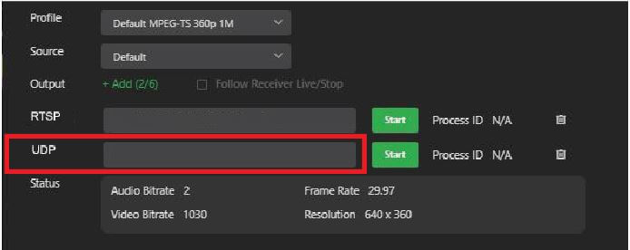
UDP – “IP” and “port” belong to the receiving destination.
- In the IP Stream window Output section, click +Add and select UDP from the drop-down menu.
- In the UDP field, add the IP and port.
Example: udp://IP:Port
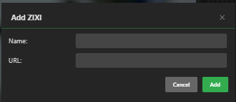
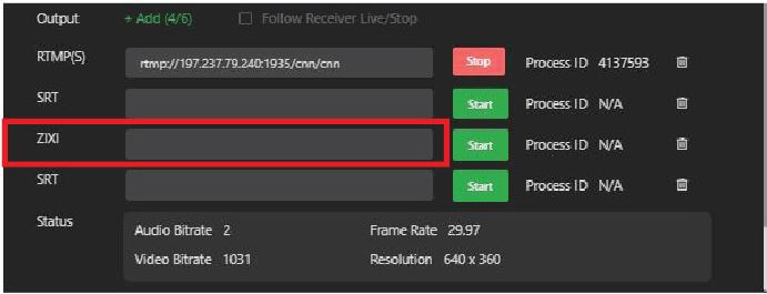
ZIXI – The ZIXI streaming protocol allows you to stream live securely by encrypting the stream between the encoder and the CDN. To use secure live streaming with ZIXI, the CDN location you’re streaming to must support it.
If a CDN provides a stream key:
- In the IP Stream window Output section, click +Add and select ZIXI from the drop-down menu.
- For ZIXI support in IP Streaming Output, the syntax is: zixi://{Broadcaster_IP}:{Broadcaster_Port}/{Channel_Name}?delay={delay_milliseconds}&bitrate={bitrate_kbps}&pwd={password}.
The last 3 parameters in the URL are optional. Default is: 1000, 10000 and empty.
- In the ZIXI field, add the IP and port.
Example: zixi://198.51.100.0:2088
SRT – “IP” and “port” belong to the receiving destination.
- In the IP Stream window Output section, click +Add and select SRT from the drop-down menu.
- In the SRT field, add the IP and port.
Example: srt://192.168.1.2.:5000
Settings – Live Encoder
The Live Encoder controls one function. Enabling the operation of the Command Center Share function when used in conjunction with a social media account.
Settings – Locate All
The Locate All feature displays the location of all live TVU Packs and their PIDs using GPS.
To view pack positions:
- Click Settings and select Locate All.
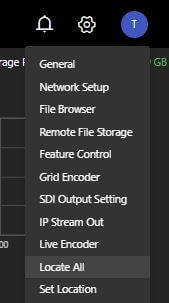
- The GPS location window opens.
- Hover over the location pin with your mouse to display the TVU pack PID.
Notes:
- In order to improve the location accuracy, make sure the TVU pack is connected to a WiFi card.
- If there is no real-time GPS data for a TVU transmitter, cached GPS data will be used for that TVU transmitter and the location pin displays red.
Settings – Set Location
The Set Location feature allows users to select Global and China connectivity settings for their remote location.
Caution: Select China only if your receiver location is in China.
Complete the following steps to set the location:
Note: This information is used for Grid mapping functions.
- To set the server’s location, click Settings and select Set location.
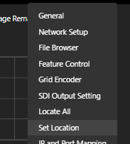
- The Set Location window will display.
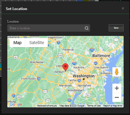
- Enter the address in the Location field, then press Save.
Settings – IP and Port mapping
Note: For more information about port forwarding refer to the latest TVU Port-forwarding guidelines document.
To access the IP and Port Mapping feature:
- Click Settings and select IP and Port Mapping.
- The IP and Port Mapping will display.
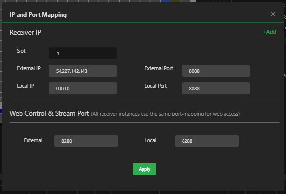
- Enter the External and Local IP addresses in the appropriate IP and Port Mapping fields.
- Click Apply and close the window.
Settings – VLAN Setting
The VLAN tunnel feature enables you to establish a virtual network between the TVU One in the field and a receiver or VLAN Server to a VLAN client in the studio and all other devices connected to these two devices.
How to enable VLAN server
To enable VLAN server:
- Click Settings and select VLAN Setting.
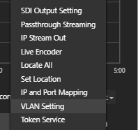
- The VLAN Setting window will display.
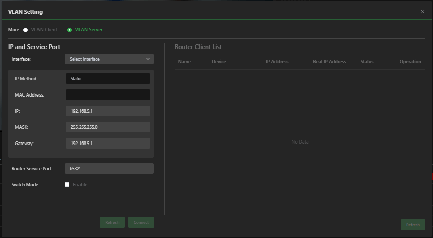
- Select the VLAN Server radio button. In the VLAN Interface line, click the Select Interface drop-down menu and select an unoccupied Ethernet port.
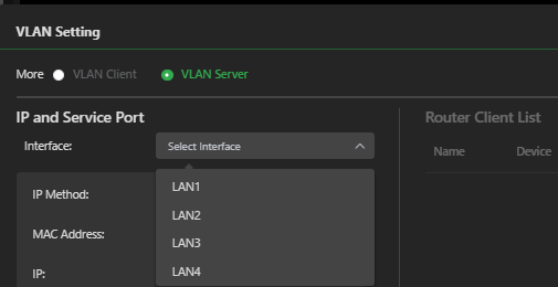
Note: There are usually 2 to 4 Ethernet ports on the back of the server. Ensure the port you select is unoccupied.
The VLAN server address is preassigned to the selected open port and is not yet enabled.
IMPORTANT: Before you enable the VLAN server, note that your receiver will become a router server and all other devices connected to the same network are assigned a VLAN IP address.
- Click Connect. An Alert message displays with a prompt to confirm the action.
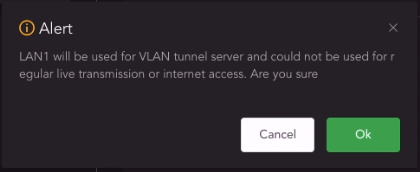
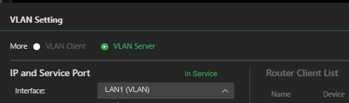
- Click OK to enable VLAN server. The selected port will display (VLAN), and “In Service” will display in green.
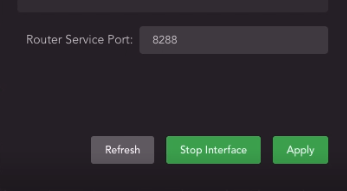
- To add your TVU One to the Router Client List in the VLAN Setting window, go to the TVU One hotspot page and navigate to the router configuration page. Enter the VLAN server port and IP information.
- To stop the interface, click Stop Interface.
Settings – Token Service
To pair a pack transmission with a receiver, source owners can create and send a Token allowing access to their source using the Token Service feature.
To create and set a token:
- Click the Settings and select Token Service.
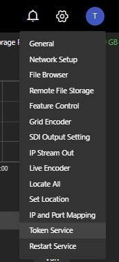
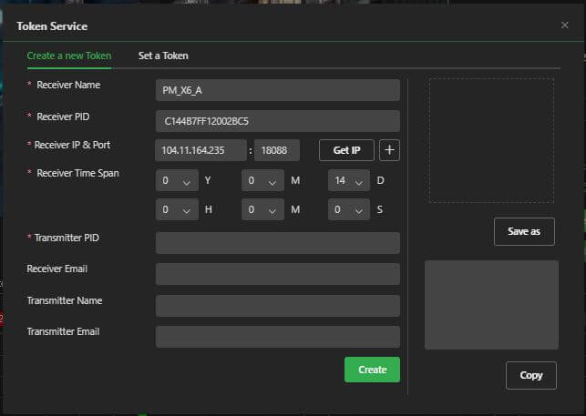
- The Token Service window will display.
- Enter the Receiver name.
- Enter the Receiver PID and click Get IP.
- Enter the Receiver Time Span.
- Enter the Transmitter PID.
- The remaining fields are optional.
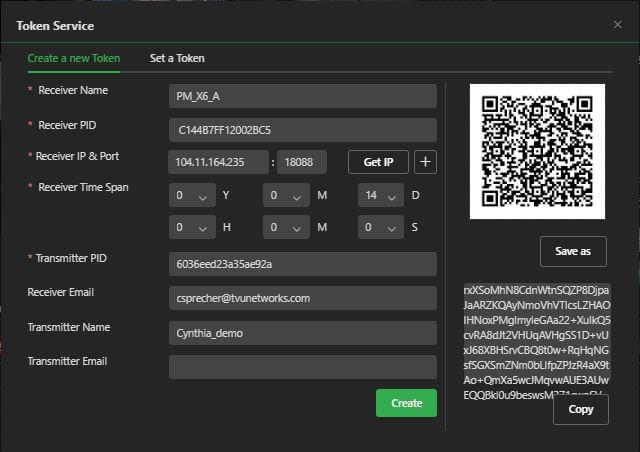
- Click the Create button.
- The Token link appears as a link and QR code. Click Save as or Copy, then email the link to the recipient.
- Click the Set a Token tab.
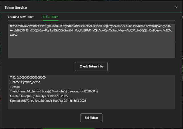
- Click Set Token.
Self-service token management
Token Service is also accessible by clicking Settings > Token Service in the TVU Command Center User Interface. The TVU Anywhere app integrates with the Token feature, allowing an operator to perform unlimited automatic server pairing without the intervention of TVU Support. Using the Token Service feature requires activation of a token license from TVU Support.
TVU Networks recommends using the updated self-service pairing method in the Command Center interface to create and manage tokens. Refer to the latest “TVU Anywhere Token Quick Start User Guide” and “TVU Grid Token Quick Start User Guide” for detailed instructions.
Settings – Restart Service
The Restart Service feature can now be accessed from the Settings menu. This feature resets the Receiver user interface after enabling or disabling features from the Feature Control window.
To use the Restart Service feature:
- Click Settings and select Restart Service.
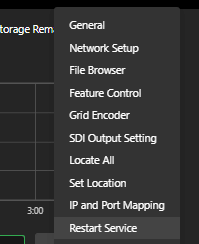
- The Restart Service Alert window will display.
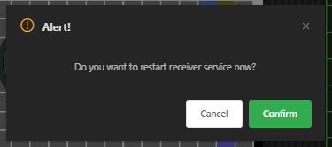
- Select Confirm to restart the service.
TVU Partyline feature integration with TVU receivers
The Linux v7.7 and above TVU receiver officially supports the TVU Partyline product.
A TVU transceiver can receive a stream directly from Partyline and output to SDI. The SDI input source on the transceiver can be used to send a return video stream to Partyline. For more information, refer to the “TVU Partyline Quick Start User Guide.”
Vision Tag settings
The Vision Tag feature allows an operator to configure visual feature detection and to identify landmarks and celebrities. This feature can also be configured to detect human faces and improper or indecent content in the image details. Refer to the “TVU Transcriber Feature guide” for detailed information.
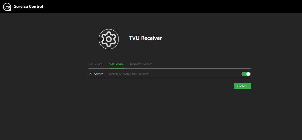
Service Control features
The Service Control link on the TVU Receiver landing page allows users to enable FTP, SSH, and Media Server.
To access these services:
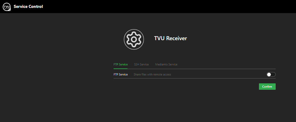
- Log in to the TVU Receiver landing page, then click the Service Control link.
The Service Control page will display.
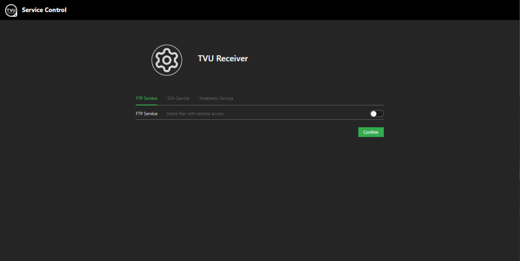
To enable FTP Service:
- Click the FTP Service tab and move the slider to the right until green, then click Confirm.
- Click the back arrow to return to the TVU Receiver landing page.
To enable SSH Service:
- Click the SSH Service tab and move the slider to the right until green, then click Confirm.
- Click the back arrow to return to the Receiver landing page.
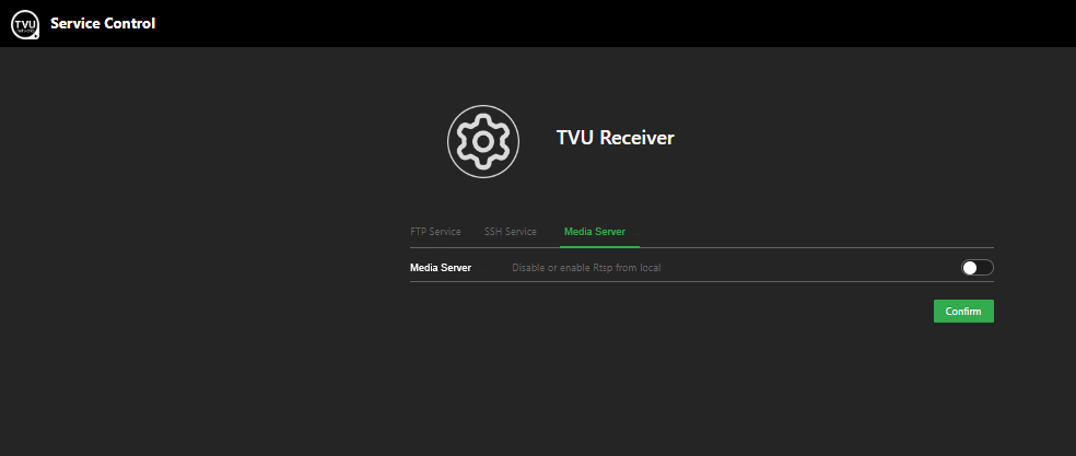
To enable Media Server:
- Click the Media Server tab and move the slider to the right until green, then click Confirm.
- Click the back arrow to return to the Receiver landing page.
Working with recorded content
This chapter explains file-based workflows.
Data transmission panel – Live and record mode tabs
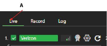
The Live and Record tabs are located on the top left of the data transmission panel.
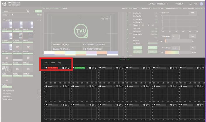
The data transmission panel Live and Record tabs control different modes of operation:
(A) Live mode: The Live tab is the primary interface used during a Live transmission. When the Live tab is selected, the Bitrate, Delay, and Operational Mode buttons display. In addition, the status of each of the data card network connections is displayed in the data card panel.
(B) Record mode: The Record tab displays selectable recorded files by date. By clicking a date. Users can preview, download, and manage the TVU Transmitter’s stored footage.
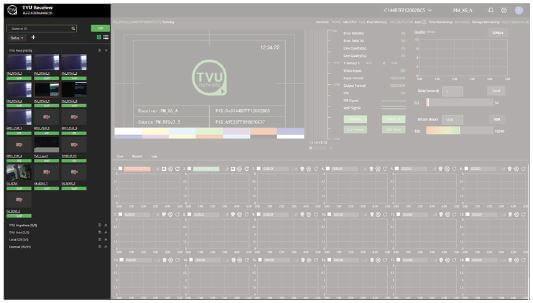
Record mode operations
The Record tab displays recorded content timelines and file management operations. This panel is shown in the following image.
Record mode
The Record tab allows users to preview, download, and manage the TVU Transmitter’s stored footage, which includes any files transferred using the Auto Sync function. Files transferred using FTP can also be accessed from this interface.
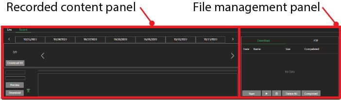
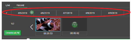
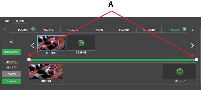
Recorded content panel
The recorded content panel has the following controls and functions:
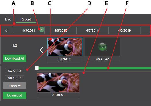
(A) Recorded content timeline: The timeline displays clips initiated by date.
(B) Number of clips indicator: The green-circled numbers next to the date indicate the number of clips available. Refer to the recorded content timeline as shown below.
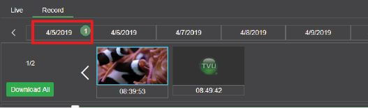
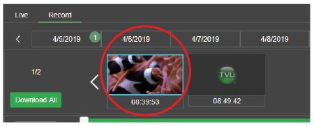
(C) Clip thumbnails: Thumbnails of selected clips from the recorded clip timeline will display below the timeline. The start time for the clip is also displayed below the thumbnail. The currently selected clip is outlined in blue.
(D) When you highlight a thumbnail, its start and end times appear in the left column below the “Download All” button.
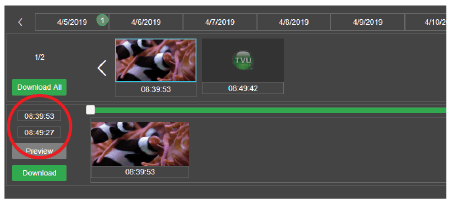
(E) Clip extraction timeline: A thumbnail of an extracted clip displays and can be edited in the clip extraction timeline.
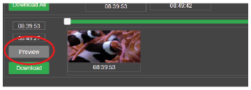
(F) Clip scrub bar: Thumbnails by a frame of a selected clip can be marked by sliding the white beginning and ending markers on the green clip scrub bar shown below.
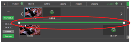
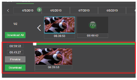
After a clip is scrubbed, the operator can preview the clip by pressing the Preview button, which will initiate a live transmission of the clip.
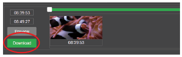
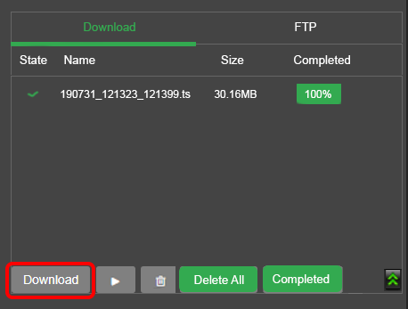
To transfer the clip, click the Download button. The file download is displayed in the file management panel. The download status displays in the Download tab records list during the download.
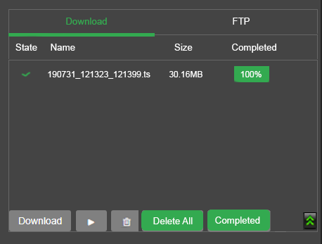
File management panel
The file management panel has the following file management controls and functions:
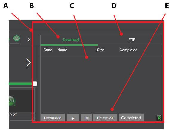
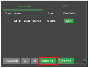
(A) File management panel: The file management panel provides the controls to view, delete, download, and export stored data.
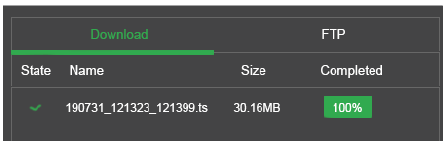
(B) Download tab: The download tab displays clips downloaded from a TVU transmitter. Once a clip has been downloaded, the stored data can be viewed, deleted, or exported using the playout and control functions within the file management panel.
Note: A file may be played before the transfer operation completes.
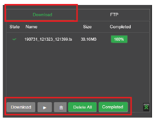
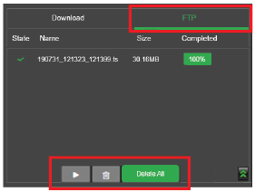
(C) FTP tab: The FTP tab displays files uploaded from an FTP client. Once a clip is uploaded, the stored data can be played or deleted.
(D) Record list: The record list in the download tab displays clips downloaded from the recorded content panel.
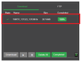
(E) Playout and download control: Once a clip has been 100% downloaded, the stored data can be viewed, deleted, downloaded, or exported using the playout and control functions.
Preview, mark, and download stored data
To preview, mark, and download a recorded transmission, complete the following steps:
- Click the Record mode tab in the data transmission panel. The Recorded content panel displays.
- If the TVU Pack is in Live mode, select Stop in the source panel’s top right corner. This will stop the live transmission and change the status to standby.
The system is now ready to manage the stored data. The downloaded, stored data is paused if you need to return to live mode. The download process will resume when the live transmission is stopped again. - Review the recorded content timeline. Click to select the desired clip from the green numbered clip indicators.
- Locate the green scrub bar (A) in the “Recorded content panel.” Slide the left start cursor to the start of the time selected (Mark in).
- Slide the end cursor to the end of the time selected (Mark out). After a few moments, the system will generate thumbnails of the in and out points.
- After the mark-in and mark-out points are completed, click the Download button.
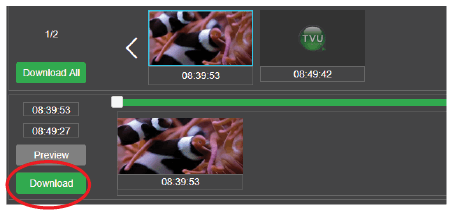
- Refer to the file management panel’s Download tab for the download status. The download status will display 100% upon completion.
File management – Pause, play, delete, and convert stored data
The File management panel Download tab displays a list of clips downloaded from the recorded content timeline. The File management panel allows an operator to pause, play, delete, and convert recorded content.
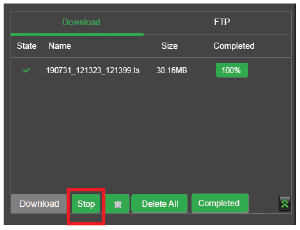
Pause a file download
Complete the following steps to pause and resume the download process of stored data:
- Before the download completes, select the file and click the Stop button.
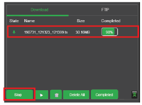
- Click the Download button to resume downloading the file to your local drive.
Play a file
Complete the following steps to play stored data from the file management panel:
- Select the file from the file list and click the Play button to play a file.
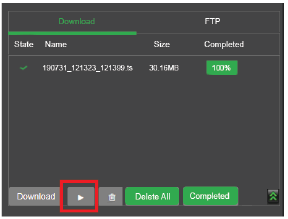
- To stop the file from playing, click the Stop button.
Delete a file
Complete the following steps to delete stored data from the file management panel:
- Select the file from the file list and click the Delete button to delete a file.
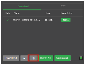
- To delete all files in the file list, click the Delete All button.
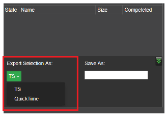
Exporting a file
Complete the following steps to export stored content into the TS or MOV file format:
- To export stored content, click the green arrows to open the export menu.
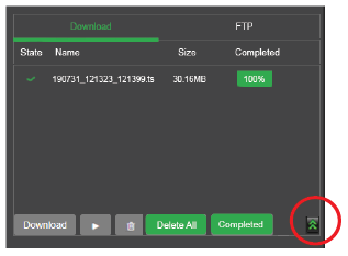
- Click the TS drop-down menu and select an Export format.
- Rename the file to be exported in the Save As field and click the Export button to download the transmitter’s video onto the server.
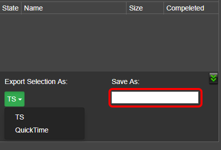
- Wait for the “Completed” column export status to reach 100%. Wait for the export status of the “Completed” column to reach 100%, then the file transfer can be played out.
By default, the file is written to a local storage directory where the last characters are the unique PID of the TVU Pack. There will be one folder for each paired pack on a server paired with multiple packs.
Accessing downloaded files from the local storage directory
To access the File browser feature from the Settings menu:
- Click Settings and select File Browser.
- You may also access the File Browser from the TVU Receiver landing page. Click File Browser in the list of links.
Complete the following steps to access your downloaded content:
- To Log in to the File Browser, Enter the following:
User ID: tvu
Password: Enter the last 8-digits of the PID using all caps
The Root file directory displays.
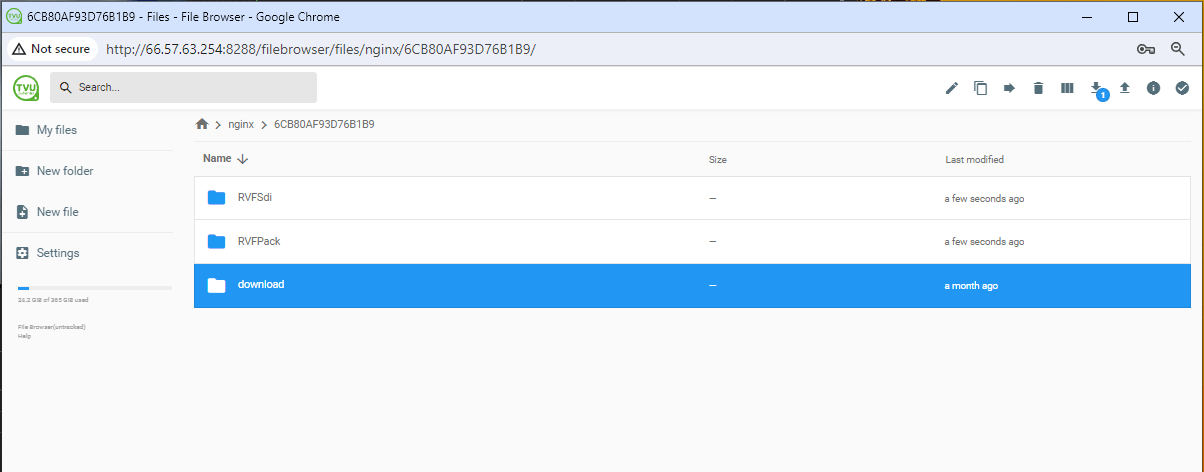
- Click the nginx folder, then the Server folder name.
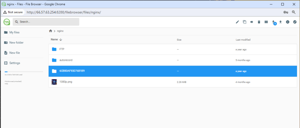
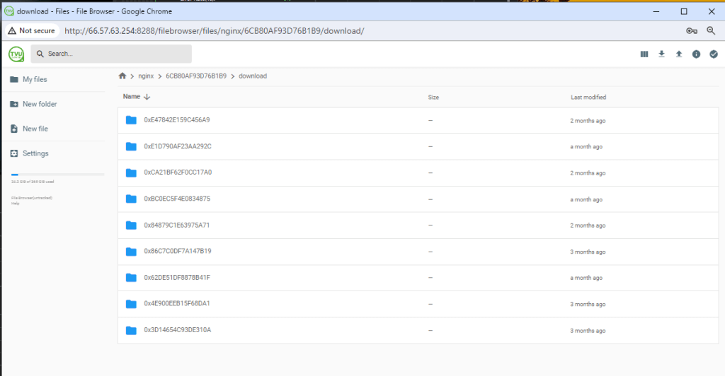
- Click the download folder to display the Packs’ unique PID folder(s).
- Click the Packs’ PID folder to display the downloaded file(s).
- Select the file(s) you want to download.
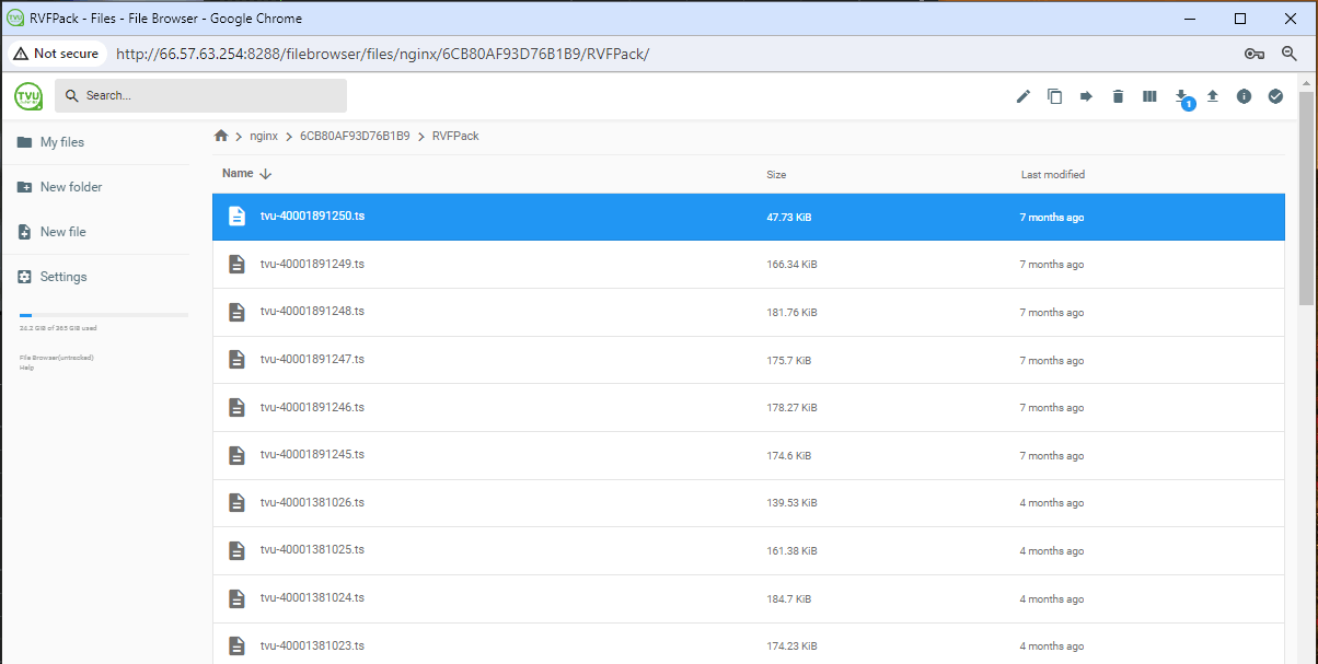
- Click the Download icon in the upper right corner of the page. You can select and download multiple files at one time. The number of downloaded files is in a blue circle next to the download icon.

- When finished, click close the window.
Remote File Storage service
The Remote File Storage service allows users to automatically copy downloaded files from the TVU server to an FTP or AWS server destination. Use the Remote File Storage window to enable the Progressive Download, Auto Sync feature, and perform FTP destination management.
Note: Linux v7.9 and higher supports the Samba (SMB) protocol. The LucidLink protocol is also supported for customers that have a LucidLink license.

The Remote File Storage window displays.
- Click the Destination Management settings icon to configure your FTP file destinations.
Note: When adding an S3 type destination, AWS credentials are required to access this feature.
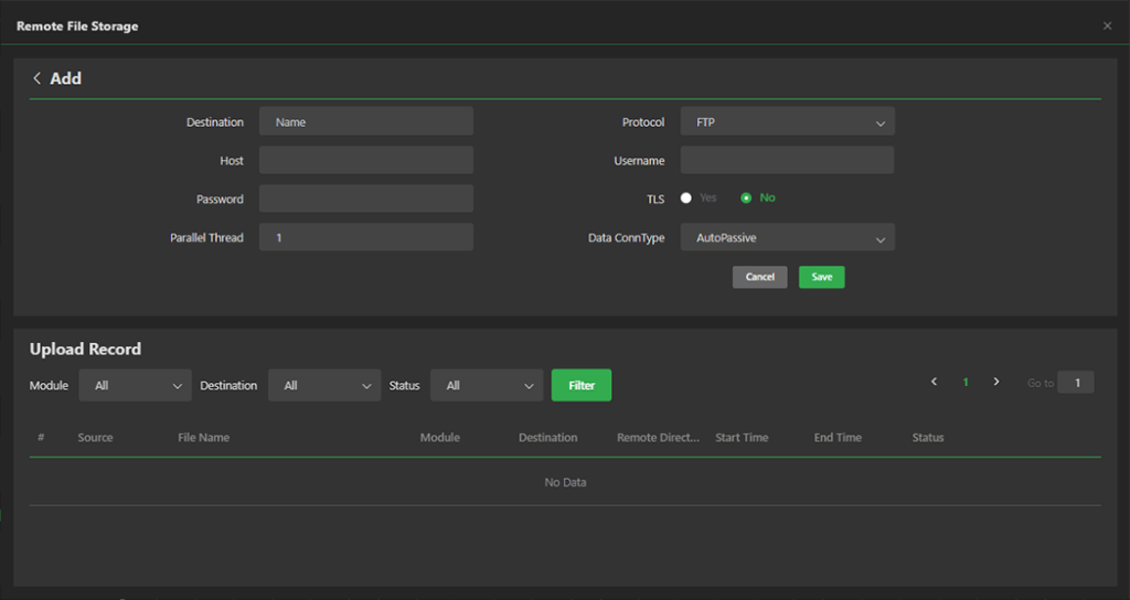
- Click the Add button in the Destination Management panel.
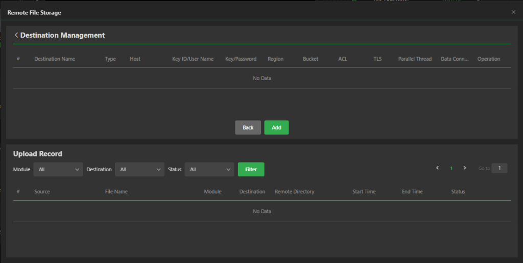
- The Add panel displays. Select a destination from the Type drop-down menu and enter the required information.
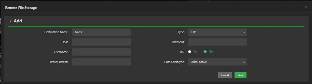
- If you select AWS from the Type drop-down menu, enter your AWS S3 support information accordingly:
- Enter a Destination Name
- Enter an Access key ID
- Select your Region
- Select the ACL
- Select Type AWS
- Enter your Secret Access key
- Enter your Bucket
- Click Save. Your AWS destination is now configured.
From this point onward, all downloaded content from TVU transmitters and content uploaded via the AutoSync feature will be copied to your selected destination.
Remote File Storage – Upload Preferences panel
The Remote File Storage window Upload Preferences panel includes the following features you can enable, edit, or disable.
Auto Sync feature
- To edit the Auto Sync upload destination, click the edit icon.
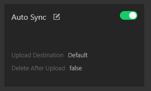
- Click the Upload Destination drop-down menu and click +Add.
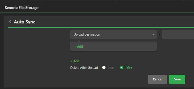
- Enter your new information in the Add panel and click Save.
File Downloading feature
- To edit the File Downloading upload destination, click the edit icon.
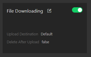
- Click the Upload Destination drop-down menu and click +Add.
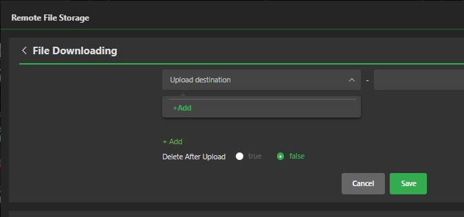
- Enter your new information in the Add panel and click Save.
Progressive Download feature
- To edit the Progressive Download upload destination, click the edit icon.
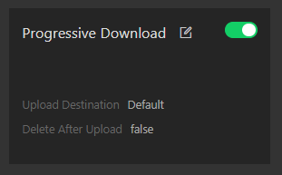
- Click the Upload Destination drop-down menu and click +Add.
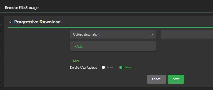
- Enter your new information in the Add panel and click Save.
Upload Record panel
The Upload Record panel will display a list of all uploads.
Logging in to the Remote File Storage service remotely
To remotely log in to the Remote File Storage service, have your server’s static IP address available, and complete the following steps:
- Open a Web browser window and enter:
http://external_IP_Address:8288
(Where External_IP_Address is your server’s static IP address)
- Click Enter. The TVU Receiver landing page displays.
- Click Remote File Storage. The TVU Receiver Web Control login page displays.
- To Log in to the TVU server UI, Enter the following:
User ID: tvu
Password: Enter the last 8-digits of the PID using all caps
- Click Login. The Remote File Storage page displays.
Appendix A – Network and firewall configuration
This section provides related support documentation for network and firewall configuration.
TVU Networks® recommends that you assign a static IP address to the TVU server to ensure the network configuration remains stable.
Contact TVU Networks support if you want to use a configuration other than the one specified in the this user guide.
The following configuration allows the transmitters and servers to link with each other and permit video transport automatically.
Complete the following steps to configure your TVU Pack router or firewall:
- Allow TCP Outgoing traffic from the TVU server on port 3970.
- Allow UDP Outgoing traffic from the TVU server on port 123.
- Permit all TCP/UDP incoming traffic for port 8088 to the server.
- Forward all traffic arriving on port 8088 of the external firewall interface of the IP address of the TVU server.
Recommended firewall configuration for remote control of the server from an iPad or smartphone
The TVU Pack hotspot feature allows remote configuration of the TVU Pack server settings from a smartphone. To enable this feature, permit all TCP incoming traffic for port 8288 to the receiving terminal; forward all traffic arriving on port 8288 of the external firewall interface to the IP address of the TVU Receiver. This port is configurable.
Bandwidth requirements
TVU Networks recommends a stable, low-latency connection with guaranteed bandwidth for best results. Allowances should be made for the bandwidth of incoming TVU transmitter transmissions based upon the following criteria:
- Each TVU server can utilize up to 20 Mbps of downstream bandwidth per live video feed.
- A minimum of 20 Mbps upstream bandwidth per TVU server is required for all features to function efficiently.
TVU server port-forwarding guidelines
TVU has developed a separate internal document for port-forwarding information. Please refer to the latest “TVU Server Port-Forwarding Guidelines” for Models VS3100, VS3200, VS3250, VS3500, VS3550, VS3600, and VS3650. If you are a customer, contact TVU Support for detailed information.
Appendix B – Network Diagnostics and Port Testing
The TVU receiver running Linux v7.9 and higher has an easy-to-use Network diagnostic tool called the Port Test tool. The Port Test tool allows a user to run diagnostic testing on all incoming and outgoing ports. NTP status can also be tested.
To use the Port Test tool, complete the following steps:
- Click Port Test on the Receiver landing page.
The Receiver Web Control Login page displays.
- To log in to the TVU server UI, enter the following:
User ID: tvu
Password: Enter the last 8 digits of the PID using all caps. - The Network Diagnostics page opens.
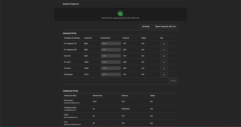
- Fill in the mapped ports before testing the network.
- Click the Get Ready button. The Alert message displays.
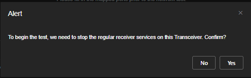
- To begin the test, click Yes to confirm that the regular receiver services on the transceiver can stop.
- Click Test or Test All from the Inbound and Outbound ports or NTP panels.
- After testing is complete, click the Restart Transceiver After Test button.
Adding a custom NTP server
Users can add a custom NTP server or backup server using the Custom NTP Service. Users can also configure their TVU receiver as a private server when not connected to the internet.
To enable Custom NTP Service:
- In the receiver web interface, click Settings > General.
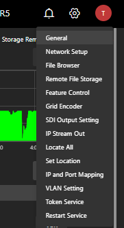
- Move the Custom NTP slider to the right until it turns green.
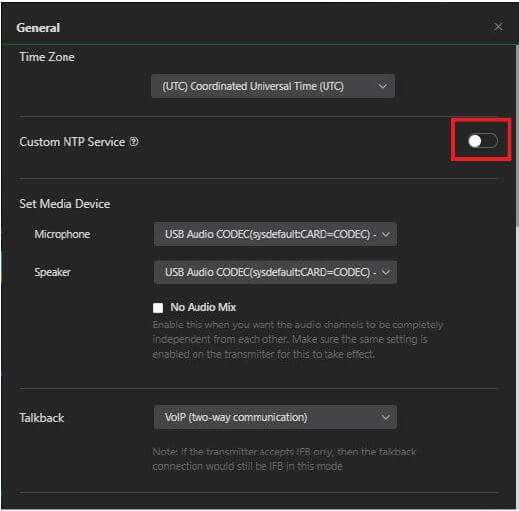
- Enter the IP address/Domain name, and Port information for the server or backup server.
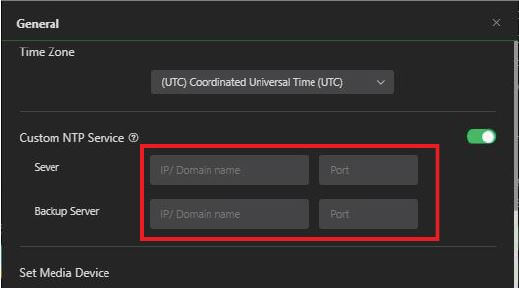
- Click Apply and close the window.
- Move the slider to the left to deactivate this feature and return to the default TVU setting.
- To test your NTP status, click Port Test on the Receiver landing page and scroll to the bottom of the window.
- Click Test in the NTP Status panel.
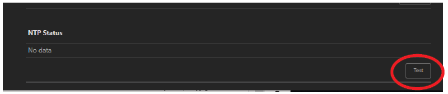
© Copyright 2025 TVU Networks Corporation. All rights reserved in all media.
Document Part Number: TVU Server Software UG Linux v8.2 Rev L EN 04-2025