Contents
- Chapter 1 – Introduction, setup, and base operation
- Features overview
- About this guide
- Models RE975, RE980, and RE990 front panel overview
- Rack Router 5G setup procedure
- Powering the TVU Rack Router 5G On and Off
- Network connection and configuration
- Rack Router 5G configuration
- General Settings – Router Server
- WAN/LAN Settings
- Hotspot configuration
- WiFi configuration
- Intelligent Speed Limit
- Chapter 2 – Advanced Configuration
- Advanced Settings module
- Typical Applications
- Expansion and remote backup
- Chapter 3 – Antenna Configuration Rack Router 5G Models RE975, RE980, and RE990
- Chapter 4 – Product Specifications
TVU Rack Router 5G Hardware Setup and User Guide
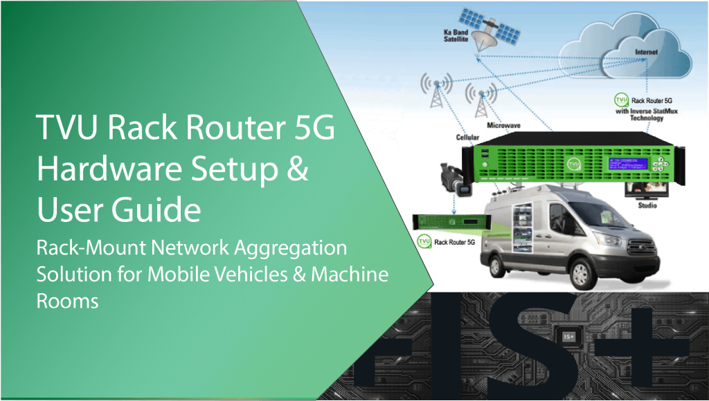
TVU Rack Router 5G is a versatile rack-mount network aggregation solution designed specifically for mobile vehicles and machine rooms. It has a 2RU height and up to 6 built-in 5G mobile cellular networks or four built-in 4G plus two built-in 5G mobile cellular networks. It can also connect with satellite, microwave, WiFi, and Ethernet, providing vehicles with stable Internet access capability of up to 1Gbps bandwidth.
Chapter 1 – Introduction, setup, and base operation
TVU Rack Router 5G Models RE975, RE980, and RE990 are a part of the TVU ecosystem. TVU Rack Router can provide vehicles with stable Internet access with bandwidth up to 4Gbps. The Rack Router aggregates multiple bandwidths, including cellular 3G/4G/LTE/5G, satellite, microwave, WiFi, and Ethernet connections, to provide highly reliable, high-speed Internet access and Network acceleration.
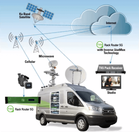
TVU Rack Router 5G overview
TVU Rack Router 5G applies TVU’s proprietary Inverse StatMux Plus (IS+) technology, which can provide a reliable network transmission in the most challenging environments (such as moving vehicles).
When a single network connection is interrupted, or bandwidth fluctuates, the overall aggregate network bandwidth link will not be affected, and the video stream and various network applications will not be interrupted. At the same time, the external antenna can be mounted externally to ensure the best signal strength.
Features overview
TVU Rack Router 5G models RE975, RE980, RE990:
- The Rack Router supports multiple router server connections in a 2RU rack-mount form factor.
- Router connection – Easy one click to start and connect.
- Supports aggregation with any mix of cellular, Ethernet, WiFi, satellite, and microwave.
- TVU Rack Router, model RE975 – This rack-mount (2RU) Network aggregation solution is designed as a field unit with IP input. The model RE975 includes six 4G modems and four Gigabit Ethernet ports. It is for use with IP cameras and a TVU router.
- TVU Rack Router 5G, model RE980 – This rack-mount (2RU) Network aggregation solution is designed as a field unit with IP input. The model RE980 includes four 4G modems, two 5G modems, and four Gigabit Ethernet ports. It is for use with IP cameras and a TVU router.
- TVU Rack Router 5G Max, model RE990 – This rack-mount (2RU) Network aggregation solution is designed as a field unit with IP input. It includes six 5G modems and four Gigabit Ethernet ports. It is for use with IP cameras and a TVU router.
- Multi-link numbers – At least six 3G/4G/LTE/5G cellular networks can be bundled simultaneously. Multiple Ethernet, microwave, Ka-band, Ku-band, and BGAN satellite links can also be aggregated through network cables.
- The Rack Router supports WAN, WLAN, 3G/4G/5G, satellite link, and other multi-network bandwidths, up to 6 mobile, 4 WAN, and 1 WLAN bandwidth aggregations.
- It supports Internet Protocol Security (IPSec), Generic Routing Encapsulation (GRE), IPIP, Point-to-Point Tunneling Protocol (PPTP), Layer 2 Tunneling Protocol (L2TP), and OpenVPN.
- Supports the CA digital certificate.
- Supports flexible and fast communication switching of multiple servers.
- Supports DHCP Server function.
- It supports multiple parameter management methods, such as web local management or central management based on the cloud.
- Supports FTP, HTTP, IMAP, NTP, POP, RTP, RTSP, SMTP, SSH, and Telnet.
- It supports history and real-time viewing with Web-based Management, Kanban, and Analysis Tools.
- LAN Dynamic Host configuration protocol – Supports up to 10 devices.
- Ships with external WiFi and 5G modem antennas.
- Contains easily accessible front panel SIM card slots for easy configuration.
- The rack router supports Internet Control Message Protocol (ICMP) detection, heartbeat packet detection, and other link detection functions, as well as LCD panel status monitoring (displays the running status) to ensure a stable and reliable wireless network.
About this guide
This Rack Router 5G User Guide provides specifications and instructions for setting up and operating three Rack Router 5G Models.
- Model RE975 is a field unit with IP input. It includes six 4G modems and four Gigabit Ethernet ports. It is for use with IP cameras and a TVU router.
- Model RE980 is a field unit with IP input. It includes four 4G modems, two 5G modems, and four Gigabit Ethernet ports. It is for use with IP cameras and a TVU router.
- Model RE990 is a field unit with IP input. It includes six 5G modems and four Gigabit Ethernet ports. It is for use with IP cameras and a TVU router.
The main topics include:
- Rack router front and rear panel overviews.
- Rack Router hardware configurations.
- Setting up the Rack Router Models RE975, RE980, and RE990.
- Operating the TVU Rack Router.
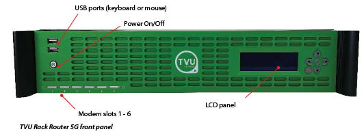
Models RE975, RE980, and RE990 front panel overview
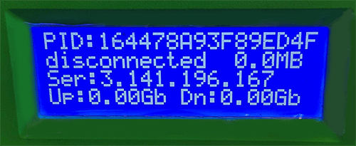
The TVU Rack Router 5G front panel features connections, indicators, and controls. The Rack Router ships with WiFi and 5G modem antennas to support six modems. SIM card slot numbers start from left to right (SIM1 -SIM6). The front panel LCD displays the device’s PID, the server connection status, the router server IP, and the device’s real-time uplink and downlink bitrate.
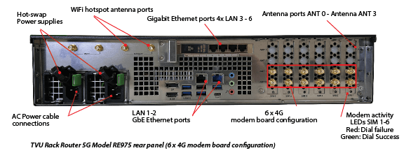
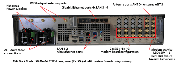
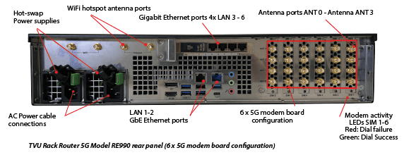
Models RE975, RE980, and RE990 rear panel overviews
The TVU Rack Router 5G rear panel features the following connections.
Rack Router configurations
Modem board number from right to left (SIM 1 to SIM 6):
- 6 x 5G Configuration – 6 modems all support the 5G network.
- 2 x 5G + 4 x 4G Configuration – The 5G modem boards are installed into SIM 1 and SIM 2 slots. The 4G modem boards are installed into the SIM 3 to SIM 6 slots.
- 6 x 4G Configuration – The 4G modem boards are installed into the SIM 1 to SIM 6 slots.
Network port numbers from left to right:
- LAN1 and LAN2 ports (corresponding to slots 12 and 11) are all set to WAN mode by default.
- LAN3, LAN4, LAN5, and LAN6 ports (corresponding to slots 13, 14, 15, and 16) are all set to LAN mode by default.
- All ports are set to DHCP by default.
- Ports can be changed at any time to WAN/LAN mode to join aggregation.
Rack Router 5G components
The TVU Rack Router 5G models ship with the following components:
- TVU Rack Router hardware product (2RU height)
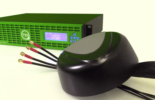
- Six outdoor antennas with a 3-meter-long feeder
- Four WiFi antennas that can be used for WiFi or hotspot
- Power Cables
Rack Router 5G setup procedure
Refer to the front and rear panel overviews for Rack Router 5G connection descriptions and locations to assist with the setup procedures. Contact TVU Support if you have any difficulties during the setup process.
Complete the following steps to set up the Rack Router 5G:
Caution: The insertion and removal of the SIM cards must be completed when the product is powered off otherwise, the card may not be recognized, or the card reader may be damaged.
- Locate the SIM card slots 1-6 on the front panel. Press a paperclip or similar tool on the left black dot to release each SIM tray.
- Insert the Micro SIM cards 1 – 6 into the SIM card trays. Orient each SIM with the top-notched corner facing left before inserting the card into each tray. Then, push in on the tray until it clicks.
- Connect the Ethernet cables to the Ethernet ports on the rear panel. The product has four network card interfaces, all of which are LAN ports by default and have the DHCP function. The card interfaces can connect external Ethernet cables to provide network connections for external devices.
Note: You can also choose to set one or more of them as LAN network ports on the “Common Settings > WAN Settings” page.
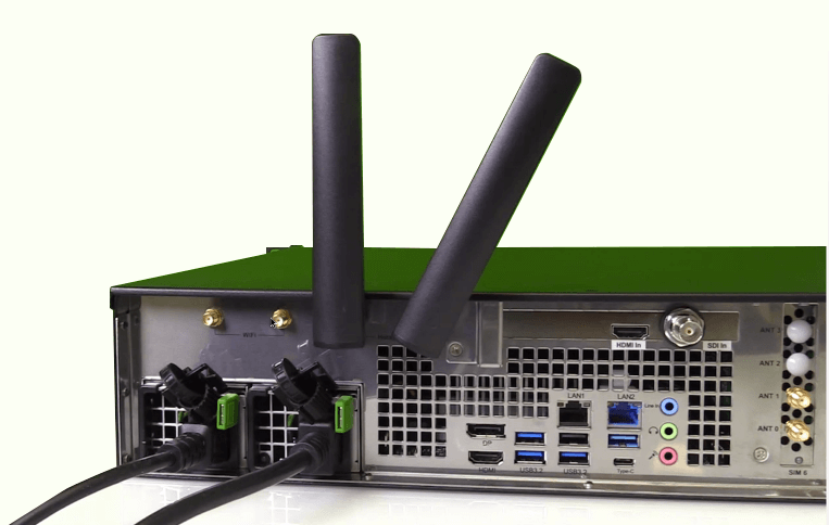
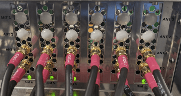
- Connect the antenna connector to the modem connection on the rear panel:
- 5G modem module, from bottom to top, ANT 0, ANT 1, ANT 2, and ANT 3. Refer to the topic “Antenna Configuration Rack Router 5G Models RE975, RE980, and RE990” for more information.
- There is one 5G modem antenna (one per modem) with four connectors. Users should install the 5G antennas at least 20 centimeters apart.
- If required, connect WiFi MIMO antennas to the top left WiFi connectors to support the MIMO mode configuration for LTE downloading (it does not support uploading).
- Connect the WiFi and Hotspot antennas to the WiFi or Hotspot pins on the rear panel.
Connect two external WiFi/Hotspot antennas to the Hotspot pins to aggregate bandwidth for your WiFi signal:
- WiFi-1 and WiFi-2 correspond to 2 WiFi antennas
- You can use the WiFi antenna as the hotspot antenna, which uses the same pins.
Connect 2 WiFi hotspot antennas to produce the router’s hotspot:
- The HOTSPOT-1 and HOTSPOT-2 pins (corresponding to 2 WiFi antennas) are set to 5 GHz by default.
WiFi MIMO antennas
5G modem antenna
- Connect the factory-supplied AC power cables to the rack router power supply connections on the rear panel and AC power source.
- Connect the computer display to the rear panel display or HDMI output port to view real-time system status.
Powering the TVU Rack Router 5G on and off
Complete the following steps to power on/off and restart the Rack Router 5G:
- To power on the TVU Rack Router 5G, press the power button on the front panel’s left lower section.
The PID number of the unit displays on the Rack Router 5G LCD screen during boot up. - Press and hold the power button down for more than four seconds to power off the TVU Rack Router 5G. The indicator light goes out, and the device shuts down.
Note: The TVU Rack Router 5G will automatically restart if the power button is pressed in and held for less than four seconds.
TVU Rack Router 5G front LCD panel indicators
The rack router front panel LCD displays the device PID, the server connection status, the router server IP, and the devices’ real-time uplink and downlink bitrate.
Network connection and configuration
You can use two methods to connect your PC or Laptop to the rack router.
Using the Hotspot (5 GHz by default)
Connect to the wireless network named “Router_XXXX” through a computer or mobile phone (where XXXX is the last four digits of the device PID). The password is the last eight digits of the device PID, and the letters are all uppercase.
Using a Network card
Connect the Ethernet port of the Rack Router with a network cable, and connect the other end to the computer. The computer must be configured to obtain IP mode automatically.
If you want to run a speed test, use a 1Gbps network cable.
By default, the router automatically assigns an IP address to the computer.
The IP range will be 192.168.4.x
Rack Router 5G configuration
The Rack Router 5G can be configured by logging in to the Router Center UI using a mobile device or computer. Chrome and Safari are supported browsers.
Complete the following steps to log in and perform the configuration operation:
- Open a Chrome or Safari Web browser and enter: http://192.168.4.1/
- The Web configuration page is displayed.
- After entering the device login page, enter the user name admin and password admin to enter the Web configuration page.
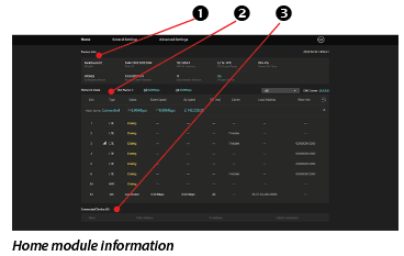
The Web configuration page contains three main modules: Home, General Settings, and Advanced Settings. It supports two languages, English and Chinese. The language of the browser you visit is selected by default.

- Click the Home module. The Home module displays the following device status:
(1) Device info
(2) Network State
(3) Connected Devices
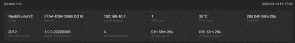
Device info panel
The Device info panel displays the following information:
- Device model
- Device PID
- LAN IP address
- CPU load
- CPU temperature
- Boot time
- Software Version
- Router Center Version
- Dial module version
- Connection duration of the Main server
- Connection duration of the Backup server (this would display multiple if applicable)
Network State panel
The Network State panel displays the following information:
Aggregation status:
- Slot number with connection
- Total uplink and downlink bitrate
- Router server IP address (Maybe more than one; all are displayed by default, and the user can manually choose which ones to display)
- DNS server
- All link’s statuses include:
- Slot number
- Link type
- Status: Dialing/Connection/Connected
- Up Speed and Down Speed (Uplink and downlink bitrate)
- Each link’s RTT (ms) time, which refers to the link’s quality
- Carrier
- Local address
- SIM card connection
- Base station connected to the SIM card information
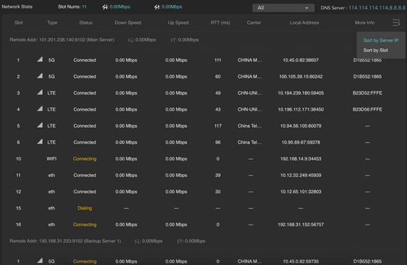
Network State panel status title bar
The status title bar at the top of the Network State panel displays the following information:
- Number of currently aggregated links
- Total download and upload speed
- The server address and port currently connected
- The DNS server currently in use
Detailed description of status information:
- Click the top right menu to select Sort by Server IP or Slot by Slot if it has multiple servers.
- Signal strength icon: Shows the strength of the 2G/3G/4G wireless signal.
- Type: Shows the connection network information of the SIM card in the current slot, 2G/3G/4G, or WiFi and WAN.
- Status:
- Dialing: After inserting the SIM card, the device will automatically dial when turned on. If dialing fails or the device is forced to find a better signal, it will continue dialing until successful.
- Connecting: Dialing is successful, connecting to the server.
- Connected
- Down Speed: shows the instant down speed in Mbps of the SIM card in the current slot.
- Up Speed: shows the instant up speed in Mbps of the SIM card in the current slot.
- RTT: shows the real-time delay of the network connection from the router to the gateway.
- Carrier: Shows the location’s carrier.
- Local Address: Is the address Server assigned to this network connection on the router.
- More Info: Shows the base station information connected to the SIM card.
Notes:
- When the rack router has upload and download traffic, the corresponding single-channel network speed is displayed in the upload speed and download speed columns. At the top of the list is the aggregated rate, the sum of all connection rates, which is equal to the sum of all 4G/5G connections, WiFi, and WAN connections.
- The page will refresh automatically in about 3 seconds. Refresh the browser manually if you need to get the latest information more frequently.
Connected Device panel
The Connected Device panel displays the device number, MAC Address, and IP Address currently connected to the router.
Note: Only the device that uses the router DHCP to assign IP is displayed in this panel.

General Settings – Router Server
This step covers selecting a router server using Auto and Custom modes when connecting to a separately deployed router server.
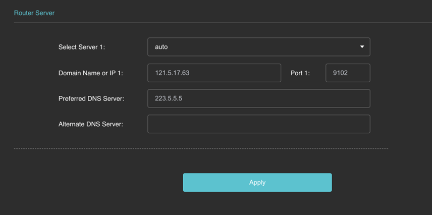
Auto mode
To connect the router to the server in Auto mode, complete the following steps:
- Click the General Settings module > Router Server.
- Select the server that the router needs to connect to, and it will automatically connect by default after a successful restart or boot.
- You can allocate and adjust the router server automatically by the system or manually select the designated gateway. After the server is correctly connected, the aggregation Internet service can be provided.
The default setting is Automatic mode. After the Rack Router is turned on, it will automatically connect to the server.
Custom mode
To connect the router to the server in Custom mode, complete the following steps:
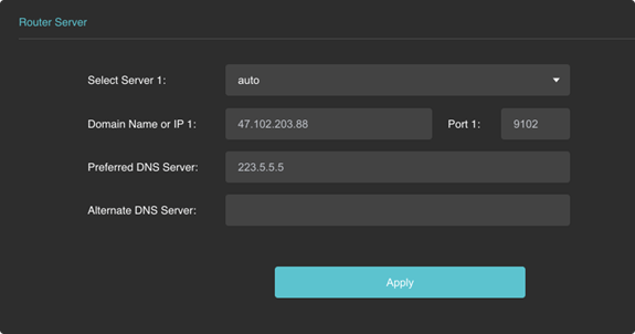
- Click the General Settings module > Router Server.
- In the Router Server pop-up window, click the Select Server 1 drop-down menu and select Custom.
- Enter the correct router gateway IP address and port to ensure the router gateway server is running.
- Enter the region’s DNS address to ensure the correct domain name resolution. Click the Plus icon to connect to multiple servers simultaneously. Using multiple servers provides a better Internet experience.
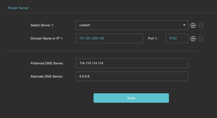
- After setting the correct information, click the
Applybutton. If the connection to the router gateway server is correct, a “Setting success” prompt is displayed.
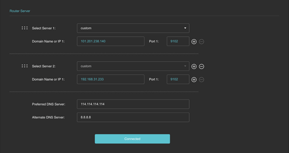
The server address that has been connected is also displayed on the state page.
For each successfully dialed network device, the server has a connection.
- If you manually set the DNS, we recommend that you set the DNS to 114.114.114.114. Make sure that modifying the DNS takes effect; otherwise, it will cause a failure when accessing the Internet.
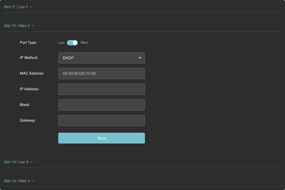
WAN/LAN Settings
To switch the network port of the rack router to a Local Area Network (LAN) or Wide Area Network (WAN), complete the following steps:
- Click the General Settings module > WAN.
- In the Router Server pop-up window, move the Port Type slider to LAN to switch to a LAN port type. The unified built-in DHCP service works and can be configured in advanced settings.
- Move the Port Type slider to WAN in the Router Server pop-up window to change to a WAN port type.
- Set the IP acquisition method of the Ethernet bandwidth as Static IP or DHCP (the WAN port IP acquisition method), MAC address, IP address, mask, gateway, etc.
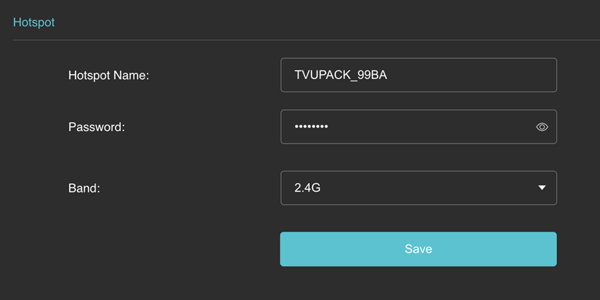
Hotspot configuration
To connect the device’s Hotspot, complete the following steps:
- Click the General Settings module > Hotspot.
- In the Hotspot pop-up window, set the Hotspot Name, Password, and Band of the device’s Hotspot (2.4G/5G). External devices can connect to the device’s Hotspot to access the Internet. Use the specific naming convention for your Hotspot name as shown in the example below.
- Click the Save button.
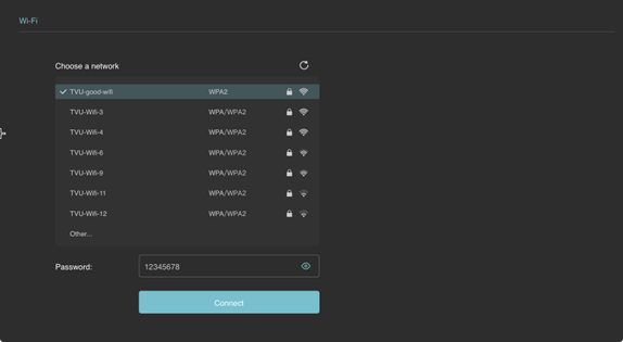
WiFi configuration
Users can connect to external WiFi Hotspots to increase the bandwidth that can be aggregated.
To connect to external WiFi Hotspots, complete the following steps:
- Click the General Settings module > Wi-Fi.
- In the WiFi pop-up window, choose a network, enter the Network’s password, and click Connect.
Intelligent Speed Limit
Users can set the device’s maximum upload and download speed, the priority of a single card, and other settings. The default is unlimited and displayed as “0 Kb/s.” Users can also change the bandwidth unit shown on the page at the top right of the list.
To configure the Intelligent Speed Limit, complete the following steps:
- Click the General Settings module > Intelligent Speed Limit.
- In the Intelligent Speed Limit window displays.
- Click the Kb/s menu at the top right of the window to change the bandwidth displayed on the page.
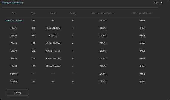
- Click the Setting button to set the maximum download and upload rate of the device’s aggregated bandwidth and the use priority and maximum download and upload speed of a single card.
Note: The more significant the priority value, the more priority it is provided; the rate unit is displayed according to the unit selected at the top right of the table, as shown in the figure below.
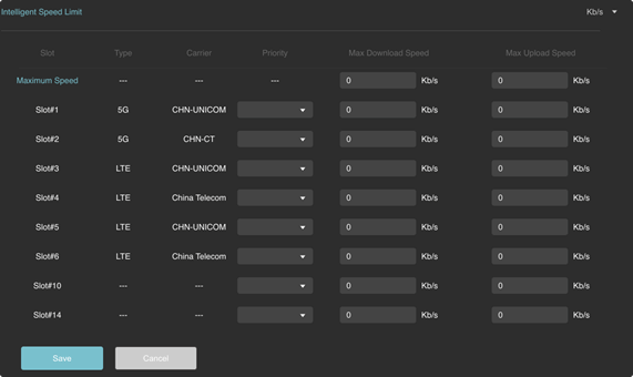
The product will automatically select and allocate the bandwidth usage if the priority of multiple cards is set. The low-priority network link is used when all the high-priority links cannot meet the bandwidth requirements.
Chapter 2 – Advanced Configuration
This section provides advanced configuration functions.
Advanced Settings Module
The Advanced Settings module allows users to set up the following Advanced configurations.
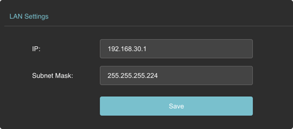
LAN Settings
- Click the Advanced Settings module > LAN Settings.
- In the LAN Settings pop-up window, set the IP address and mask of the Rack Router device.
The default display is the fixed network IP address “192.168.4.1” of the aggregation router, and the mask is entered in the range 1~32.
For external devices connected to the Rack Router through a network cable, the IP allocation method uses DHCP by default. As the IP address and mask of the router change, the address assigned to the devices will also change.
- Click Save.
P2P Settings
- Click the Advanced Settings module.
- Refer to the introduction of P2P Functions in the “Typical Applications” topic for more information.
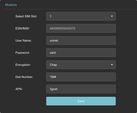
Modems
Note: General mobile phone SIM cards and IoT cards have default configurations, which need to be modified under particular circumstances.
- Click the Advanced Settings module.
- Modems: Set the parameters of the mobile SIM card to access the Internet and click Save.
Typical Applications
This topic describes typical applications for the TVU Rack Router 5G.
P2P Function
There are two typical application scenarios for P2P functionality.
Scenario 1:
P2P interconnection between the device connected to the Rack Router and the device under the aggregation gateway server.
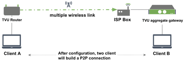
Client A configures the Rack Router
- 192.168.4.*/24 (keep consistent with advanced settings and LAN settings)
- Open P2P (configure the IP Range parameters and restart the router process without restarting the entire machine)
Client B configures the aggregation gateway server
- 192.168.5.*/24
- Open P2P (configure the IP Range parameters and restart the router process without restarting the entire machine)
Scenario 2:
P2P interconnection between devices connected to 2 rack routers under the same aggregation gateway server.
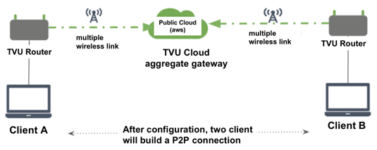
Client A configures the Rack Router
- 192.168.4.*/24
- Open P2P (configure the IP Range parameters and restart the router process without restarting the entire machine)
Client B configures the Rack Router
- 192.168.5.*/24
- Open P2P (configure the IP Range parameters and restart the router process without restarting the entire machine)
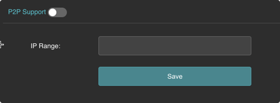
Click Advanced Settings > P2P Settings and enter the following configuration interface (the P2P function is closed by default):
After enabling the P2P function (if you have set the IP Range before, then open it again to see the last set IP Range in the input box below and apply it), you can enter the IP network segment range where the connected device is located. It supports the two input methods of “IP/mask” and specific IP range, as shown in the figure below. Add a comma “,” to separate the different IP ranges, and then click the Save button to save the settings.
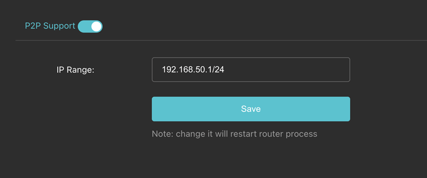
Note: The IPs of the devices at both ends cannot be exactly the same. Enabling/disabling/modifying P2P settings will interrupt the network for about 2 seconds.
NAT/No NAT switching of the server
When the router server is installed, it is configured by support.
Horizontal expansion and remote backup of the server
On the aggregation gateway server setting page, when the Auto mode is selected, the aggregation gateway that cooperates with the rack router will automatically and intelligently choose and allocate the cloud scheduling service. Currently, the aggregation service can automatically support expansion and remote backup.
Smooth expansion
When the number of rack router users increases, the aggregation gateway deployed in the cloud can smoothly expand, and the newly opened aggregation router is automatically assigned to the newly opened aggregation gateway.
Remote backup
Once the gateway device serving the rack router fails for various reasons, it will automatically switch to other available aggregation gateways to ensure uninterrupted operation of aggregation services.
Chapter 3 – Antenna Configuration Rack Router 5G Models
RE975, RE980, and RE990
This section provides antenna configuration procedures for the Rack Router 5G (Models RE975/980/990)
Rack Router v2 (RE975/980/990)
To configure the antennas on Rack Router 5G models RE975, RE980, and RE990, complete the following steps:
- To configure the model RE975 Rack Router 5G unit with six 4G/LTE modems, connect the 4G/5G external antenna SMA connector to ANT 0 and ANT 1 on all six SIM slots.
- To configure a model RE980 Rack Router 5G unit with two 5G modems and four 4G/LTE modems, connect the 4G/5G external antenna SMA connector to ANT 0, ANT 1, ANT 2, and ANT 3 on SIM slots 1 and 2 for two 5G modems, and connect the 4G/5G external antenna SMA connector to ANT 0 and ANT 1 on SIM slots 3, 4, 5, and 6 for four 4G/LTE modems.
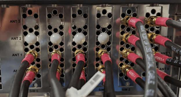
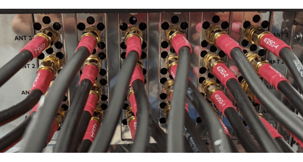
- To configure a model RE990 Rack Router 5G unit with a six 5G modem configuration, connect the 4G/5G external antenna SMA connector to ANT 0, ANT 1, ANT 2, and ANT 3 on all 6 SIM slots.
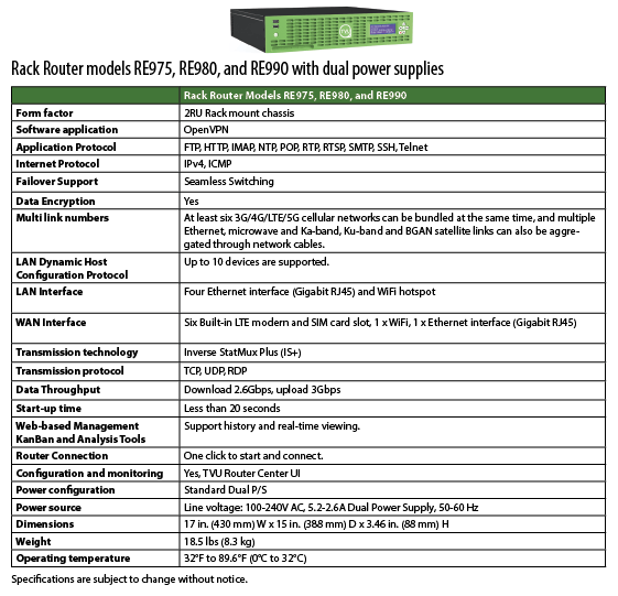
Chapter 4 – Product Specifications
© Copyright 2024 TVU Networks Corporation. All rights reserved in all media.
Document Part Number: TVU Rack Router 5G HW User Guide Rev B EN 05-2024