Chapter 1 – Introduction, software setup and configuration
TVU Networks “One” is the latest generation of portable TVU transmission devices. The TVU Networks One is based on the latest TM1100 hardware, the smallest and lightest transmitter in its class. The compact hardware design boasts a weight of just 3.9 lb. (1.79 kg) with the internal battery.
Product overview
One features up to 12 connections and an enhanced Inverse Statmux Plus, TVU’s next-generation transmission protocol. It also features six next-generation, sub-6GHz 3GPP release 16 5G embedded modems with an advanced antenna array that supports multiple antennas for each modem, making the One compatible with the most advanced 5G networks, including future network slicing.
The TVU Networks One hardware can be used with two different software variations. The One (single-channel transmitter) or the RPS One (multi-channel REMI encoder), as shown below.
The “One” Model TM1100 delivers high-definition picture quality with 0.5-second latency at 3 Mbps within an ultra-compact, rugged hardware design. The One transmitter uses the H.265/HEVC or H.264 encoding and compression standard to deliver greater efficiency in data use and increased transmission stability. The 4K input support is optional for SDI.
With the One, live video broadcasters can fully leverage the versatility of a small, lightweight, IP-based high-definition video field transmitter without sacrificing performance, features, or picture quality. Switch from single-channel to 4-channel fully frame-synchronized REMI wireless transmission at any time.
The One model TM1100 includes an onboard, removable Li-Ion battery for unlimited runtime to give you more time for going live, recording, or transferring files.
The One can communicate using RTIL, IFB, and bidirectional VoIP between the studio and the field operator without latency.
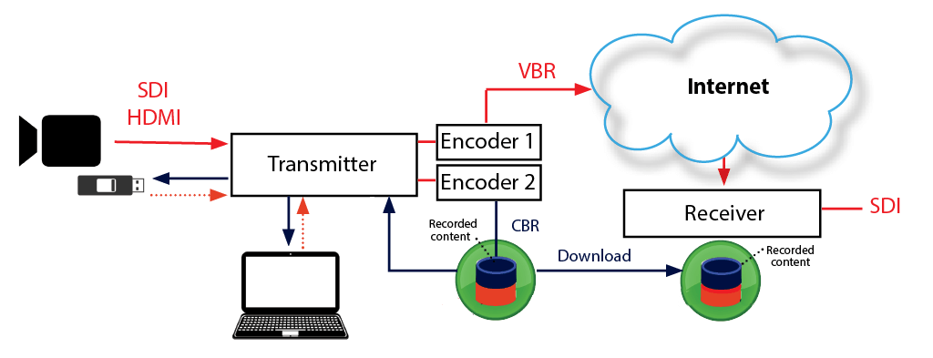
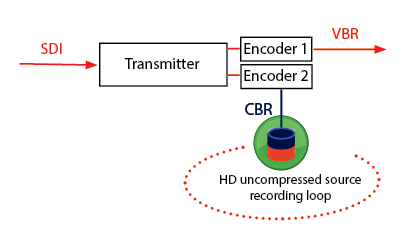
Real-time dual encoding makes it possible to go live under any network conditions by simultaneously recording a full HD copy of your video for later download.
The One model TM1100 features
The One 1-Channel (V4) transmitter can be upgraded – To an RPS One 4-Channel REMI Live encoder if needed (temporarily or permanently). The RPS One functionality is controlled via feature control and the software version is user upgradable on the LCD touchscreen.
Rugged chassis – CNCed from high-density aluminum.
On-board removable battery – For up to two hours runtime with all four channels encoding and six 5G modems. Utilize the standard TVU POWERPAC or any V-Mount/Gold Mount battery to extend runtime with hot-swap capability.
Battery run times – Internal: 2 hours (120 minutes), plus the External: 3.5 hours (210 minutes) = 5.5 hours of total run time (330 minutes).
Redesigned breathable backpack – With improved quality and durability.
5G Ready – The first and smallest 5G ready, with the latest generation Sub 6GHz, 3GPP Release 16, 5G embedded modems.
Reliable low-latency, high-quality transmission – True 60 frame per second (full motion) 4K is available for Channel 1 as a standalone.
Support for up to 12 data connections – Up to 6 embedded 5G nano (4ff) modems (w/ LTE/3G fallback), embedded 2.4/5GHz WiFi, Ethernet, and 4 USB connections for external modem connections.
Supports LTE Category 12 global modems.
Type 10 Micro SD support – Up to 18 hours of high-quality video storage. The Pack ships with a 128 GB SD card.
Onboard SDI and HDMI input. Onboard RVF HDMI output.
Color space – bit depth – 4.2.0 or 4:2:2 is standard up to 1080p), 8bit or 10 bit.
Encoding – HEVC/H.265 or H.264 video compression. Users can monitor the live-stream bitrate. If the selected transmission bitrate drops below the threshold, a visual notification is displayed on the home screen.
RVF status and version display – One/RPS One Software version 8.1 (Build 81349) or later supports RVF control via touch screen. It includes an RVF option to support viewing return video feeds from an iPhone or iPad.
RVF support – TVU Producer or SDI input at Server Hotspot stream on the same server.
VLAN mode support – Can connect to the receiver’s VLAN without having a router data plan.
GPS and Partyline status display.
Supports access to TVU Partyline as a participant (not available for 4K format).
Contents and functions
The “One” transmitter model has a robust hardware design and functions to fit the needs of any live broadcaster. The One runs on the TVU platform and includes the following functions:
Simple Worry-Free Operation – TVU pioneered a one-button operation in portable live video streaming transmitters. The One requires no in-field configuration and boots up in less than 30 seconds.
Small Form Factor, Big Features – The One is feature-rich with no compromises to performance or capabilities. To see a full list of hardware and software specifications for The One, refer to “Product Specifications.”
Versatile hardware design and operation – The One single-channel live transmitter and RPS One 4-Channel REMI Live encoder share the same Model TM1100 hardware. Single-channel transmitters ship with BNC silicon caps for unused SDI ports.
Supports 4-channel video independent transmission via feature control – The One 1-Channel (V4) transmitter can be upgraded to an RPS One 4-Channel REMI Live encoder if needed (temporarily or permanently). The RPS One functionality is controlled via feature control and is user upgradable from the LCD screen.
Inverse StatMux Plus – The One features proprietary video transmission technology called Inverse StatMux Plus (IS+). With IS+, the unsurpassed HD picture quality is dependably delivered at sub-second latency over cellular 3G/4G/5G LTE modems, even when transmitting in a moving vehicle traveling at over 60 mph/100 kph.
Powerful Real-Time Store and Forward – The One can simultaneously live stream and record. TVU has HD file transfer functionality that ensures the delivery of an HD quality error-free video clip to the studio in real time without waiting until the clip is fully recorded on the transmitter.
Digital memory card slot and video storage – Supports a 128 GB SD card (providing 8 hours of high-quality video).
Fully Compatible with TVU Grid – TVU’s IP-based video switching, routing, and distribution solution allows a broadcaster to share a live video transmission with any other TVU Grid-enabled station, operations center, or physical location. TVU Grid features very low latency when switching, routing, or distributing live video.
On-board return video feed HDMI – Use this feature to receive a high-quality, low-latency SDI return feed in the field from a TVU receiver in the studio, which can be monitored locally on an HDMI monitor.
Improved audio quality – Optimized audio transmission quality and compatibility. Supports high bit-rate audio settings up to 320 Kbps.
Support for external Bluetooth adapter (optional) – Communicate via VoIP wirelessly with an external Bluetooth adapter.
5G Ready – The system includes up to 6 embedded 5G modems (w/ LTE/3G fallback).
Support for external 5G devices – Connect to certain external 5G phones/MiFi devices to enable hotspot usage.
Closed caption pass-through – Support for embedded pass-through of closed captions for 1080i and 720p.
Support for TVU Partyline – Integrates with remote video conferencing as a One source. The TVU One can also send RTIL streams to Partyline as a TVU device.
Support for TVU Producer – Integrates with the Return Video Feed from Producer via WebR or RTL.
Speedtest feature – Supports speed testing of the transmission between the transmitter and receiver.
USB file upload – Supports USB file uploads from a flash drive.
Stream control – Supports remote streaming output of a receiver.
The One integrates with the TVU Command Center Web interface, which provides a cloud-based centralized management and control solution of all TVU devices and services. For detailed information about TVU Command Center, refer to the “TVU Command Center Set up and User Guide.”
Chapter 2 – Introduction, software setup, and configuration
Before you begin
Before using this software user guide, refer to the latest The One hardware user guide. You should identify the devices you intend to use with the unit, including cameras, cables, power sources, modems, TVU services, and unit accessories.
The TVU RPS One encoder running The One/RPS One Software version 8.1 (Build 81349) or later uses the same hardware, which features two LCD console interfaces:
The One single-channel transmitter
TVU RPS One multi-channel encoder
Note: To switch from a The One to an RPS One console, contact TVU Support at support@tvunetworks.com. Once authorized, switching consoles is performed via feature control.
About this guide
This software user guide provides detailed information about the following topics:
Operating the One transmitter
Advanced configuration settings
Monitoring and controlling the One transmitter
Advanced transmitter operations
File-based workflows
Connectivity through captive portals
TVU transmitter LCD touchscreen interface
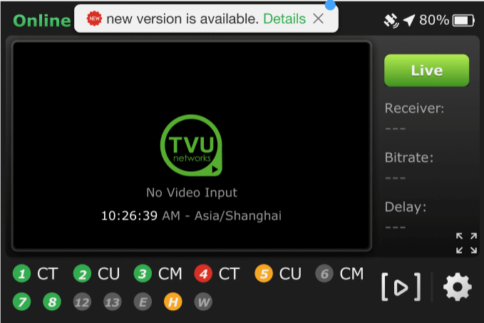
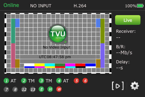
The transmitter’s LCD touchscreen interface allows transmission control in the field. When the One is first turned on and SDI connected, the user sees the status display screen.
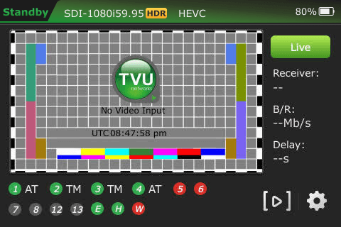
The TVU test pattern will display on the LCD screen if no transmission feed is connected.
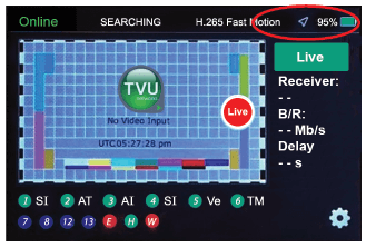
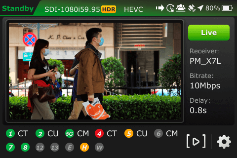
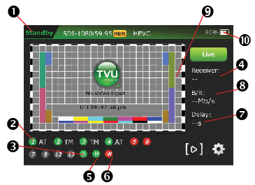
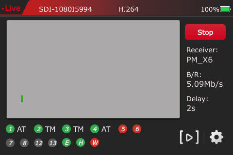
The One transmitter Live status screen descriptions
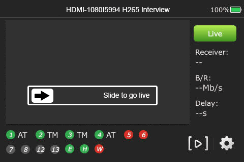
(1) Transmission Status: The transmission status monitor displays the current transmission status of the transmitter. If the LCD screen displays “LIVE,” it indicates the transmission is Live. The LCD screen will display “Online” (Standby) or Preview mode if a camera or input source is not connected to the One transmitter.
(2) Data Card Status Monitor: Displays the current number and status of all data cards connected to the One. The status of data cards connected to the One will appear as green, red, orange, or black. Green status indicates that the data card is connected. Orange status indicates that the data card is attempting to dial. The red status indicates that the data card is not connected. Black status indicates there is no card.
(3) Ethernet Connection: Displays the status of the Ethernet connection.
(4) Receiver Name: Shows the receiver name to which the unit is transmitting.
(5) Hotspot Connection: Displays the status of the hotspot connection.
(6) WiFi Connection: Displays the status of the WiFi connection.
(7) Latency Status: Displays the current latency of the transmission.
(8) Bit Rate Status: Displays the current Bit Rate (B/R).
(9) Audio Input Level Monitor: Dynamically displays the unit’s audio input level (DBFS) with graphical colors. Analog audio input is available via IFB port to embedded SDI.
For the audio mapping feature, use channels 1-2.
(10) Battery Status: Indicates the status of the battery.
Operating the One transmitter
The LCD screen on the transmitter can be operated with simple finger taps, much like a smartphone with a touch screen user interface. When accessed, the operational functions and status display interfaces available will appear as a pop-up window or drop-down menu that overlays the preview or live video input. Follow these instructions to access all the transmitter’s features and functions through its LCD touchscreen.
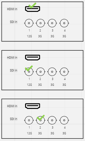
For a single camera connection:
HDMI only – Up to 4K p60
12G SDI In (1) only – Up to 4K p60
3G SDI In (2) only – Up to 1080 p60
User self-upgrade guide
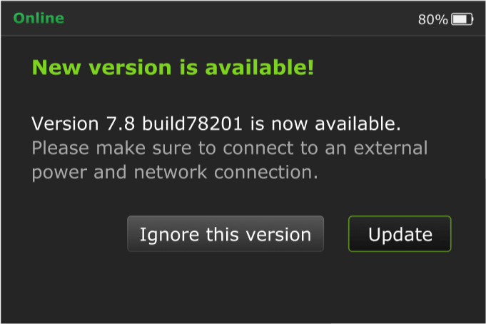
IMPORTANT: To upgrade the software from v8.0 to v8.1 contact TVU Support to enable the upgrade feature before proceeding. The device checks for the presence of the User Upgrade feature and displays a new version notification after booting.
If you need to verify your App version, tap the Settings icon > Config tab > About.
To upgrade from v8.0 to v8.1, complete the following steps:
Tap the green Details link in the notifications alert message.
A message to contact TVU Support will appear if the feature is not enabled.
The new version screen displays. Tap Ignore this version to abort the upgrade and return to the previous screen.
Tap Update to proceed with the upgrade.
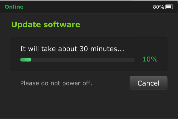
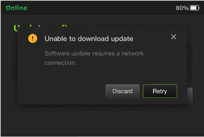
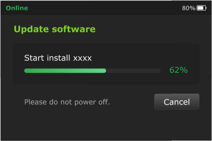
The software update is downloaded onto the device and then installed. This can take up to 30 minutes.
Note: If an error occurs during the download process, an error message displays. Tap the Discard or Retry button.
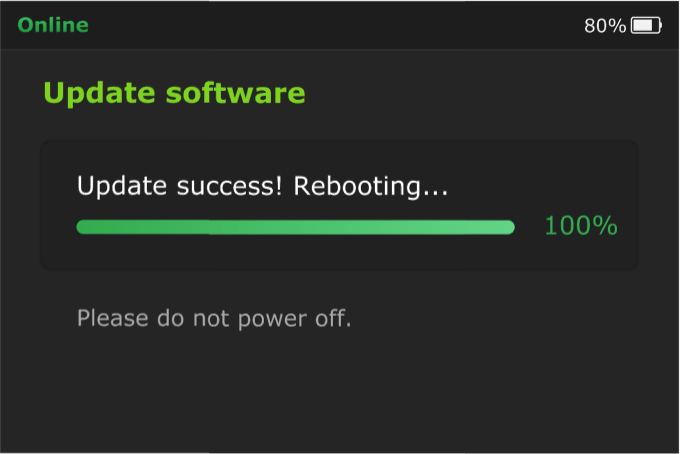
The installation process automatically starts after the download process completes.
The device will reboot automatically after a successful installation.
Selecting a receiver and going Live
All configuration options and settings are now accessible using the gear-shaped Settings icon on the bottom right of the LCD.
To go Live, complete the following steps:
Turn on the One.
Connect the The One to a camera source.
Tap the center of the LCD screen. The initial status screen displays. Tap the Gear icon on the bottom right of the screen.
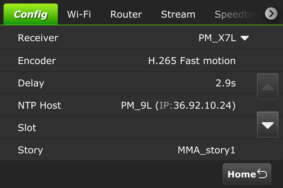
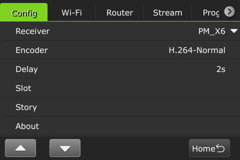
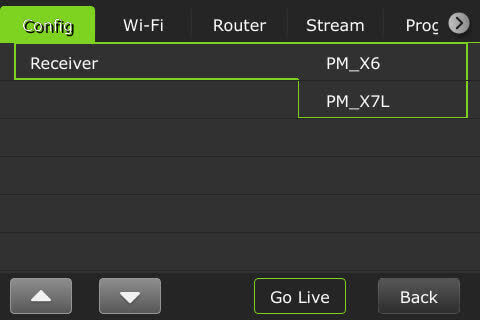
Tap Receiver in the Config tab.
Note: To return to the previous screen, tap the Home button in the bottom-right corner of the screen.
Select the receiver from the drop-down menu you want to go Live with.
Note: To Exit from going Live, touch the Back button in the bottom-right corner of the screen.
Press the Go Live button to go live with the selected receiver.
To stop a Live transmission, press the red Stop button.
When the live transmission is stopped, the LCD displays “Standby” in the upper left corner of the screen.
Selecting an encoding transmission mode
The One has true dual encoding. It encodes the same content at a fixed bitrate in the background and records to local storage. Users can monitor the live-stream bitrate. If the selected transmission bitrate drops below the threshold, a visual notification is displayed on the home screen.
The One model TM1100 supports onboard H.265/HEVC or H.264 encoding.
To select an encoding option, complete the following steps:
Touch the center of the LCD screen and tap the Gear icon on the initial status screen. The Config tab displays.
Tap Encoder.
Slide and tap to make your selection:
Note: Your selection will highlight green. The One must be in live mode before you can change selections.
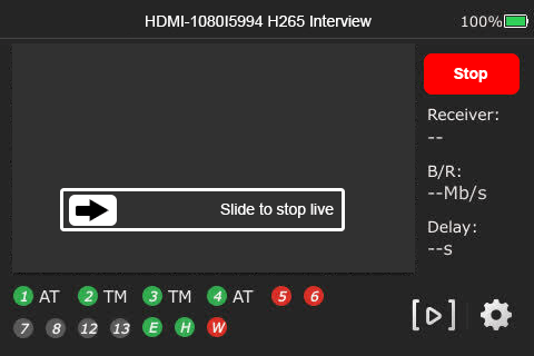
H.265 Interview: Bitrate 2048, delay 2 seconds
H.264Normal: Bitrate 5120, delay 4 seconds
H.265 Fast Motion: Bitrate 5120, delay 8 seconds
Bandwidth: Normal or BGAN mode
To save your selection, Click OK.
To exit from the menu, click the Back button.
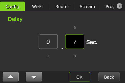
Delay management
To manage the second and sub-second Latency settings, complete the following steps:
Tap the Gear icon on the bottom of the LCD.
The Config tab displays. Tap Delay.
Note: To Exit this menu, tap the Home button.
Scroll through the menu using the up and down arrows to change the settings and press OK.
To exit from the menu, tap the Back button.
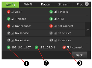
Data card monitoring
To monitor detailed encoder information along with Ethernet, hotspot, and WiFi connections, complete the following steps:
Tap the center of the LCD screen. The status screen displays. Tap the Gear icon to display the Config tab.
Tap Slot in the Config tab menu to display the Slot monitoring window. The data cards and their status display along with Ethernet, Hotspot, and Wi-Fi indicators:
(1) Ethernet (2) Hotspot (3) WiFi connection
To exit from the menu, click the Back button.
Turning off the One transmitter
To turn off the One transmitter, complete the following steps:
Press the power button once. A sliding button will display on the LCD screen.
Slide the button from left to right to power down the unit.
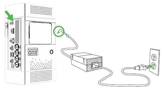
Charging the internal battery
Note: The battery will charge faster if the TVU One unit is powered off.
The One comes with an AC adapter. To charge the One, connect the AC adapter as shown.
Power button status when charging
The One displays the following power button status when the AC adapter is properly connected, and the battery is charging:
The unit is powered on when charging and displays a steady green light.
A flashing red and green light is displayed during a forced shutdown while power is on.
The unit is powered off, and charging displays a flashing red light.
When fully charged, the power off displays a steady red light.
The power light is off when the battery is not charged or connected to the unit.
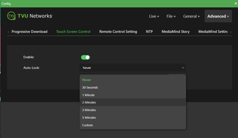
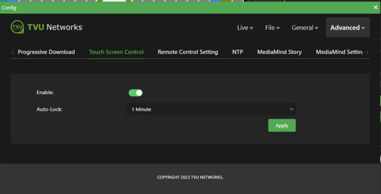
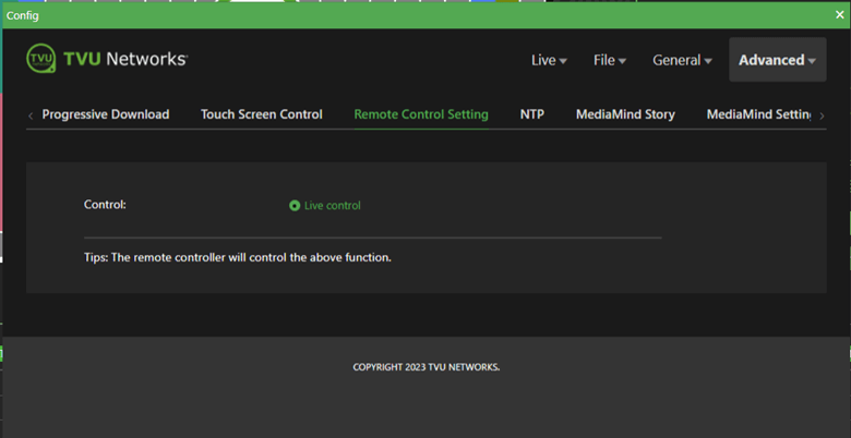
Chapter 3 – Advanced configuration
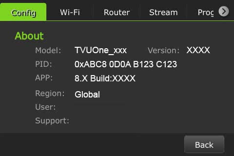
The One transmitter information
To access the One model number, Peer ID, software version, App version input, format, and transmitter configuration information, complete the following steps:
Tap the Gear icon at the bottom of the LCD.
The Config tab displays. Tap About.
The transmitter information window displays.
To exit from the menu, click the Back button.
The One status monitoring and control using a Web browser, iPhone, or smart mobile device
The TVU Transmitter’s operational status can be monitored, and various transmission functions can be controlled from a Web browser. This interface can be accessed using a standard web browser connected to the One hotspot USB port on the side panel.
Connecting the One to the internal hotspot
Complete the steps in the following procedure to configure the One to the internal hotspot using your iPhone or smart mobile device.
Configuring the One transmitter for hotspot (optional)
Search for the hotspot on your iPhone/smart device. Then, when prompted, enter the case-sensitive SSID:
TVUPACK_XXXX (Where X is the last 4 digits of the One’s PID) The default password is the last 8 digits of the TVU One’s PID
Note: All password characters are uppercase. The password can be changed in the Web UI if desired.
Connect to the SSID using your iPhone/smart device. Refer to the following examples of how the status screens display on a smart device Web browser.
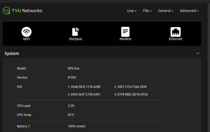
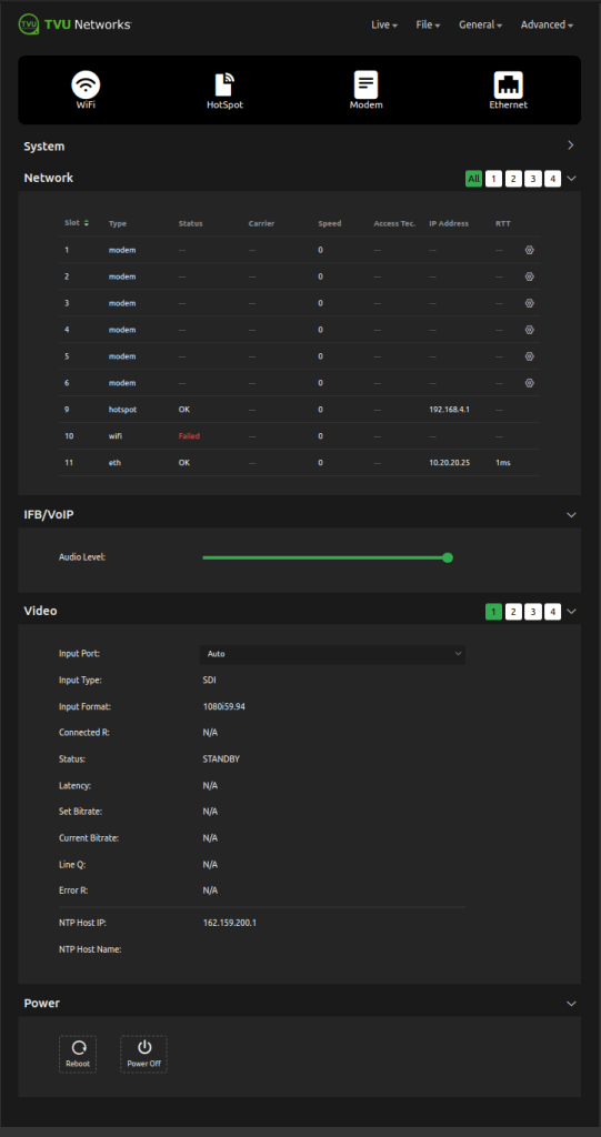
Once the connection is established, you can open a web browser and enter https://192.168.4.1 in the address line to see the One’s “System status.”
You can tap the Home button in the Config tab to view the “system information.”
The One System status screen displays.
The System status screen also provides the following information.
Network panel – Displays the current Network status. IFB/VoIP – Allows the user to change the audio level of the IFB function. It also includes analog audio input via IFB port to embedded SDI that supports up to 8 channels. This feature provides an optimized audio transmission quality and compatibility and supports high bitrate audio up to 320 Kbps. Analog audio input is possible via IFB port to embedded SDI. The audio-only option is only available after enabling the feature. Video – Displays video transmission information and status. Power – Reboot and Power off buttons.
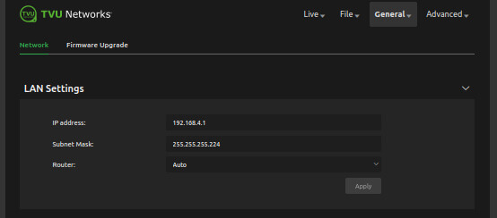
Network configuration
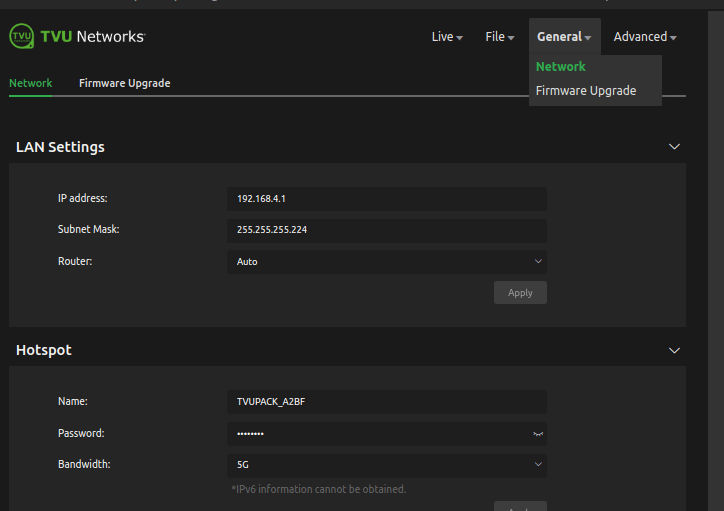
Click the General drop-down menu and select Network. This allows users to navigate to, monitor, and control all aspects of transmission.
In the LAN settings panel, Set the local LAN address of the One. The default IP address is 192.168.4.1.
Enter the Subnet Mask and select a Router setting from the drop-down menu. The default is Auto. Click Apply.
Use the following procedures to scroll through the remaining Network options to complete the configuration settings:
Hotspot
WiFi
Ethernet
Modems
The One hotspot settings
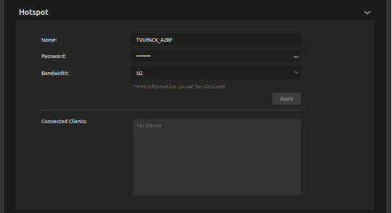
The hotspot menu provides status information about clients connected through the hotspot.
Configuring hotspot
Complete the following steps to configure hotspot status:
Click the General drop-down menu and select Network.
Scroll down and expand the Hotspot panel.
Note: The Connected Client list window displays a list of devices that are connected using hotspots.
To update the Password, edit the password field.
Note: The new password must be 8 characters and does not take affect until the system is restarted.
The hotspot feature enables a connected device to access the Internet through one of the available network connections. This access allows file transfers via FTP or any other internet connection. If higher bandwidth is required, refer to the topic “Router setting.”
To manually select the route taken (for example, a Hotel WiFi network), choose the path from the Route drop-down menu.
In the Band drop-down menu, choose 2.4 GHz or 5 GHz.
Click Apply to save your changes.
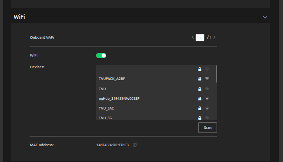
WiFi configuration and settings
The WiFi menu provides configuration information and access to change the WiFi settings. The transmitter can optionally support multiple WiFi connections by purchasing optional hardware. For more information, contact TVU Networks support.
When multiple WiFi adapters are connected, you can scan available slots for WiFi adapters and configure the WiFi login information using the One WiFi setup and configuration panel.
Configuring WiFi
Complete the steps in the following procedure to configure your WiFi settings:
Click the General drop-down menu and select Network.
Scroll down and expand the WiFi panel.
Press the Scan button to display any available networks. The available networks are displayed in the center panel. Choose the desired network from the center panel.
Move the WiFi slider to the right to enable it and connect it to the selected device.
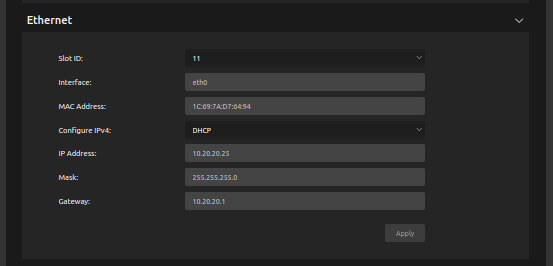
Ethernet configuration
Complete the following steps to set up and configure Ethernet in the One setup and configuration panel.
Click the General drop-down menu and select Network.
Scroll down and expand the Ethernet panel.
Click the Slot ID drop-down menu and select a slot number.
Click the Configure IPv4 drop-down menu and select a Static IP or DHCP IP method.
If your IP method is static, enter the static IP address in the IP Address field.
If your IP method is static, enter the Subnet Mask in the Mask field.
Note: The DHCP IP address is automatically generated and cannot be manually entered.
If your IP method is static, you must enter the Gateway in the Gateway field.
Press the Apply button to save your changes.
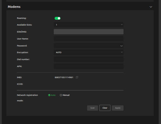
Modem configuration
The Modem screen provides modem configuration information. The TVU transmitter automatically detects many cellular data cards and will self-configure. If this is the case, no further action will be required. If a data card requires configuration, use the Modem menu to configure specific data cards.
Click the General drop-down menu and select Network.
Scroll down and expand the Modems panel.
Select slot 1 and enable the Roaming slider.
Configuring data cards
Complete the following steps to configure specific data cards:
Click the General drop-down menu and select Network.
Scroll down and expand the Modems panel.
Click the Available Slots drop-down list to display a list of available slots for configuration.
Go to the User Name field and enter the carrier user name information from the network carrier.
Go to the Password field and enter the carrier password information from the network carrier.
Click the Encryption drop-down menu and select the appropriate encryption standard.
Go to the Dial number field and enter the carrier dial information from the network carrier.
Go to the APN field and enter APN information from the network carrier.
Under the Network registration mode, select the Manual radio button when roaming.
Click the Scan button to scan for available carrier networks.
Click Apply to save any changes.
TVU Cloud services integration
The One Partyline integration scenario:
Partyline RVF sent to The One HDMI RVF output
Partyline audio sent to The One VoIP/IFB output
Partyline audio (in/out) RTIL
The One Input 1 device video source in Partyline
The One RVF HDMI output (RTIL)
The One Producer integration scenario:
Producer PGM sent to The One HDMI RVF output and associated Partyline/Producer session
PGM output from Producer (RTIL)
Partyline audio (in/out) RTIL
The One RVF HDMI output RTIL to RVF source from Producer
The One input 1 device video source in Partyline
The One Transceiver integration scenario:
SDI input for RVF to the transceiver
VoIP/IFB audio in/out from/to the transceiver
RVF encode output from the transceiver (RTIL) to The One
VoIP/IFB from/to the transceiver to The One
RVF HDMI output from The One to RVF source from the transceiver
The One input 1 device video source in Partyline
Partyline in/out of The One.
Chapter 4 – Advanced operations
Receiver status and control
Advanced control of the receivers’ Live session can be configured by using the Settings > Config tab available using the One ‘hotspot feature.
To choose the operational mode, tap the gear icon on the touchscreen, then tap Config > Encoder to select H.265 Interview, H.264 Normal, H.265 Fast Motion, SD, Tape Feed, and User Definable as receiver functions. Click OK to save your changes.
You can also use the system status page to control bitrate and delay by entering your data in the respective fields and clicking the Apply button to save your settings. Refer to “Controlling the live transmission.”
Note: You can monitor the live stream bitrate and see notifications on the Web UI and LCD touchscreen when the transmission bitrate drops below the threshold.
Controlling the live transmission
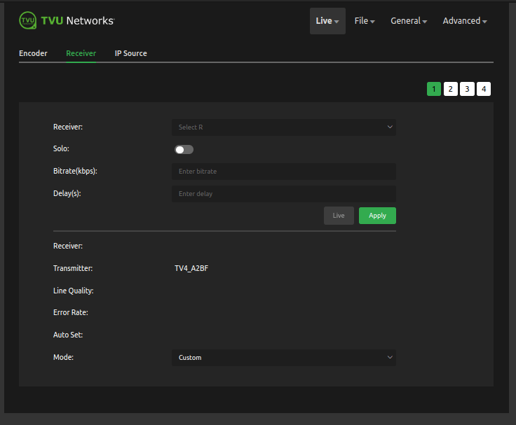
Complete the steps in the following procedure to select an alternate receiver, view its status, and set up and control a ”Live” transmission:
Click the Live drop-down menu and click the Receiver tab.
The Receiver:Select R drop-down menu to display the receiver’s name. To view and select a different receiver, click the Select R drop-down menu and select a receiver from the list.
Enable the Solo slider if you want a specific transmitter to only display ‘Online’ on the selected receiver from the Select R drop-down menu.
Enter the desired transmission bitrate in the Bitrate (kbps) field.
In the Delay(s) field, enter the desired transmission delay.
Click the Apply button to save your changes.
To Start or Stop the live transmission, click the Live button.
Note: Below the Live and Apply buttons you can view the Receiver status. Receiver status displays the current The One Receiver ID, The One Transmitter ID, Line Quality, Error Rate, and Auto Set information.
Click the Mode: drop-down menu to select an alternate Mode for optimized preset bitrate and latency based on broadcast setting(s).
Encoder status and control
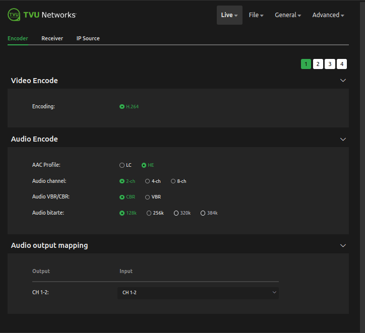
To view Live video and audio encoding settings, complete the following steps:
Click the Live drop-down menu and click the Encoder tab.
The Encoder panel displays the live video and Audio encoding along with the Audio output mapping for channel output and input.
The encoder must be set to HEVC to view and set the 4:2:0 vs 4.2.2 video encoding option.
Note: For information about the Dual encoding feature, refer to the topic “Dual-encoder feature.”
Encoder settings
The Video and Audio encoding must be set up for channel 1 before going live (e.g.) HEVC or H264 and their various configurations.
To configure the encoder setting, complete the following steps:
Click Live > Encoder tab.
Select Channel 1. The selected channel displays green.
In the Audio Encode panel, select the appropriate radio buttons.
Select 1-2 from the Audio output mapping Input drop-down menu.
Chapter 5 – Software setup, configuration, and going live
Turning on the One transmitter
Press the power button, and the One transmitter will boot up.
The initial status screen displays.
The modems begin to connect automatically.
Note: Modem removal must be completed by TVU Support or an authorized TVU reseller.
Going live
There are two ways to take your transmission live:
Tap the Live button on the initial status screen (shown below). This will default to the receiver with which you recently went live. Continue with the Going Live steps.
Tap the Settings gear, select Receiver, and choose a receiver in the Config tab. Then, go live. Refer to “Selecting a receiver and going live.”
Tap the Live button on the initial status screen to start the live transmission.
The One unit will prompt you to slide the ‘Slide to go live’ button from left to right.
Once the button is engaged, the One begins the live transmission using the last receiver with which you most recently went Live.
Selecting a receiver and going Live
All configuration options and settings are now accessible using the gear-shaped Settings icon at the bottom of the screen.
Tap the gear icon to open the Settings screen.
Tap the Config tab and tap Receiver.
Select the receiver with which you want to go live from the drop-down menu and tap the Go Live button.
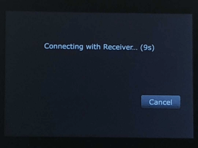
Note: When starting a live transmission from this menu, you will not be prompted to slide a button. The transmission will begin with a countdown.
If you only want to select a receiver but do not want to go Live, tap the Back button at the bottom-right corner of the LCD touchscreen.
Note: When starting a live transmission from this menu, you will not be prompted to slide a button. The transmission will begin with a countdown.
If you only want to select a receiver but do not want to go live, tap the Back button at the bottom right corner of the LCD touchscreen.
Countdown screen
Live status screen
Standby status screen
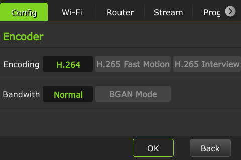
Selecting an encoder option
The One model TM1100 supports onboard H.265/HEVC or H.264 encoding.
To select an encoding option, complete the following steps:
Tap the Gear to open the settings window and the Config tab. Then, tap Encoder.
Slide to select one of the following options:
Note: Your selection will highlight green. The transmitter must be in live mode before you can change selections.
Interview: Bitrate 2048, delay 2 seconds
Normal: Bitrate 5120, delay 4 seconds
Fast Moving: Bitrate 5120, delay 8 seconds
Bandwidth: Normal or BGAN Mode
To save your selection, Click OK.
To exit from the menu, click the Back button in the bottom right corner of the screen.
Latency management
To manage the second and sub-second Latency settings, complete the following steps:
Tap the Gear to open the settings window and the Config tab. Then, tap Delay.
Use the up and down arrows to make your selection. Then, press OK.
To exit from the menu, click the Back button at the bottom right corner of the screen.
Data card monitoring
To monitor detailed transmitter information as well as Ethernet, hotspot, and WiFi connections, complete the following steps:
Tap the Gear to open the settings window and the Config tab.
Tap Slot. The Slot status window displays. The data cards and their status display along with Ethernet, Hotspot, and Wi-Fi indicators:
(1) Ethernet
(2) Hotspot
(3) Wi-Fi connection
To exit from the menu, click the Back button.
About page in the Config tab
The About page in the Config tab displays the One’s information.
Tap About in the Config tab.
Tap the Region is set to Global by default.
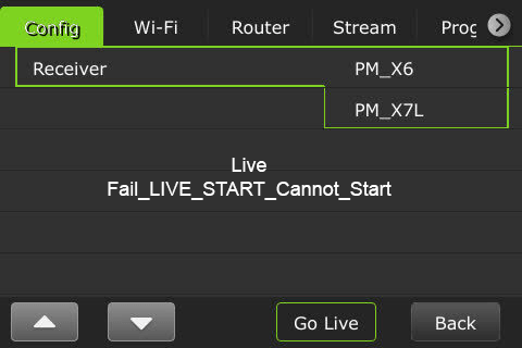
Note: You must reboot the One after changing the Receiver. Changing the Receiver during a live transmission may cause the live transmission to fail.
The following message will be displayed if a live transmission fails after reboot.
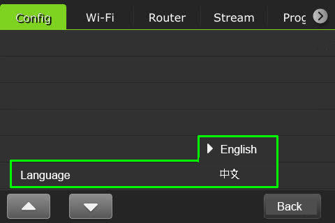
Language selection in the Config tab
The Config tab allows the user to choose English and Chinese languages. To select a language, complete the following steps:
Tap the Config tab, scroll down, and tap the Language option. The default is English.
Select your desired option using the up and down arrows.
When finished, tap the Back button.
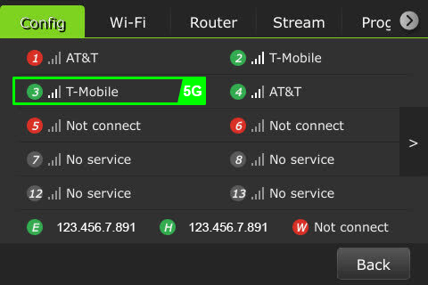
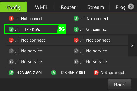
Slot selection in the Config tab
A user can view the speed of each slot in real time from the Slot selection in the Config tab. To view a slot speed, complete the following steps:
Tap the Config tab and tap Slot. The active slots display.
Select a desired slot to view its real-time speed.
When finished, tap the Back button.
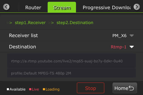
Stream tab
Using the Stream tab, a user can remotely control the stream output destination of a receiver.
Tap the Stream tab.
Select a receiver from the “Receiver list” drop-down menu. Then, select a destination from the “Destination” drop-down menu and tap Publish.
To stop the stream, tap Stop.
Note: When the Stream is Live the destination selected displays red, when loading the status is yellow. Receivers that are available display white.
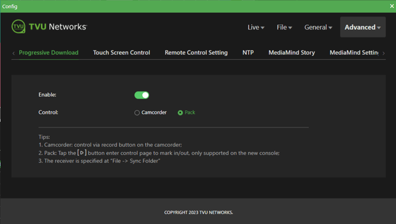
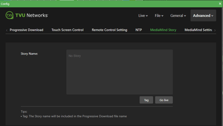
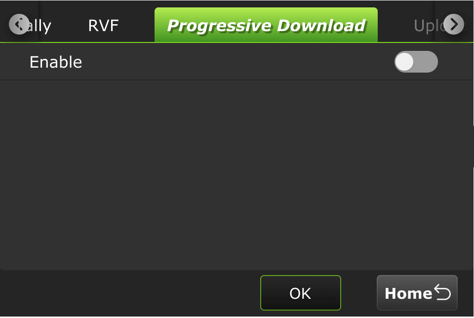
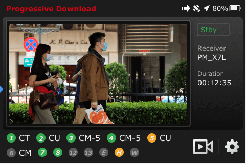
Progressive Download tab – Enable the feature
To enable the Progressive Download feature, complete the following steps:
Tap the gear icon.
The Settings menu displays. Tap the Progressive Download tab.
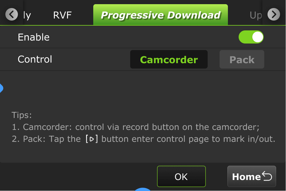
To enable the Progressive Download feature, tap the Enable slider to the right until it turns green.
Your control selections display:
The Camcorder default option is displayed and controlled by the camera’s record button.
Tap the Record button on the camcorder to display controls.
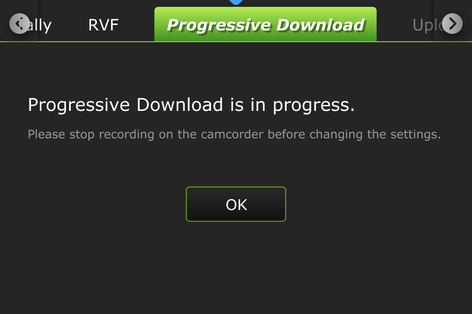
Note: Stop recording on the camcorder if you need to change your settings.
The following message will be displayed if you change the settings to the One during camcorder mode while it’s running.
Camcorder mode
Camcorder mode can only be used with an SDI input. Having the time code inside the SDI signal is requested.
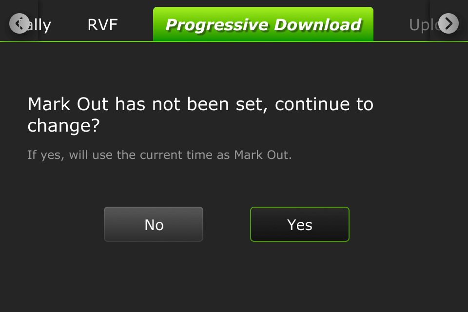
The following message displays that if you change to camcorder mode when the pack mode is running, and the in point is set, but the out point is not set, and the processing is interrupted, then it would use the current point as the out point.
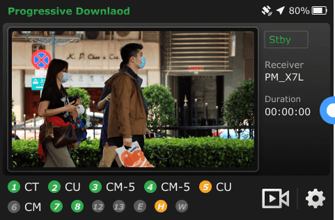
When in camcorder mode, when the camera is not recording, Standby “Stby” is displayed.
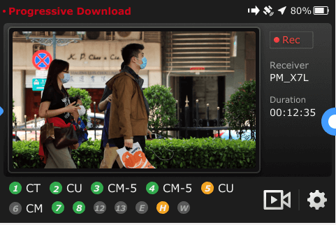
When the camcorder is recording, “Rec” is displayed.
When the camcorder is finished recording, “Stby” is displayed.
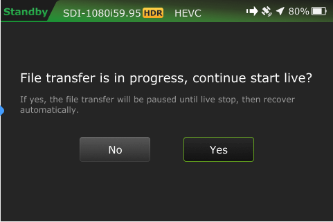
Live alert prompt:
The One (Pack) control mode
Pack mode can be used in either SDI or HDMI. A time code is not requested.
You can control the clip on the transmitter by tapping the Pack button. Tap OK, and a Success prompt displays.
Tap the Home button. Your feed will display in “Standby” mode.
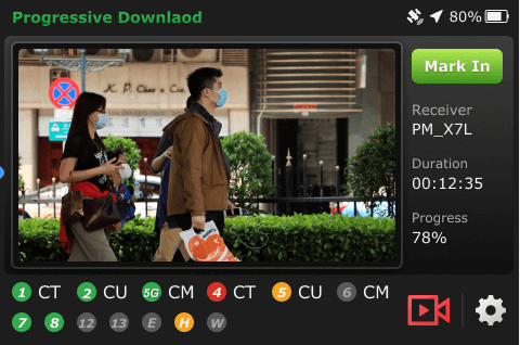
Tap the icon to enter the control page to set your mark in/out preferences.
When a file is being transferred, including Progressive Download, download, and Auto Sync, a new file transfer icon displays in the top status bar. A prompt will display if a file is being transferred when the Pack is shutting down. The transfer icon displays when a file is being transferred. Tap the file transfer icon in the status bar to enter the File Transfer page to view the details.
The icon is red when a Progressive Download is in progress.
The camera icon is red when the transmitter is live with a receiver.
Transferring and marking the file
To access the Progressive Download feature, complete the following steps:
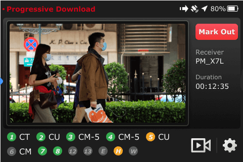
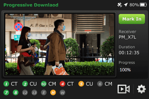
Tap the Mark in button from the Progressive Download display to mark the in point. The transfer will start automatically.
When the file transfer begins, the transfer icon displays in the status bar. The file duration displays below the Mark out button.
You can tap the file transfer icon in the status bar to enter the File Transfer page to view the details.
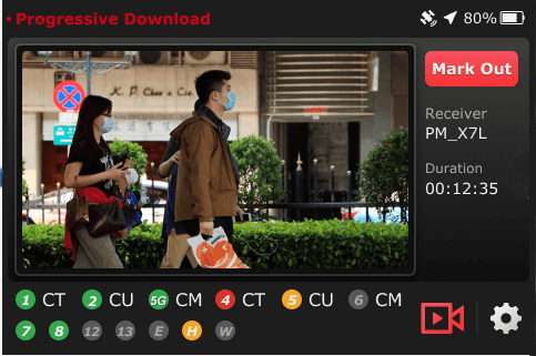
Tap the Mark Out button to mark the out point.
The processing progress of the current clip displays.
When the file transfer Progress displays 100%, continue to “Taking the clip live.”
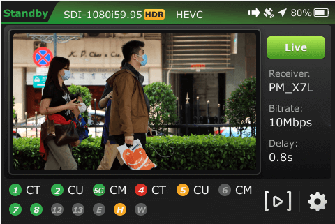
Taking the clip live
This function can also be used during live streaming after the file transfer is complete. To enter the live streaming interface, tap the icon.
The live streaming interface displays. To take your clip live, tap the Live button.
Swipe the Slide to go live button to connect with the receiver. The Live streaming interface displays.
To switch to the Mark interface again, tap the icon.
To mark your in and out points, tap the Mark In button.
Tap the Mark Out button.
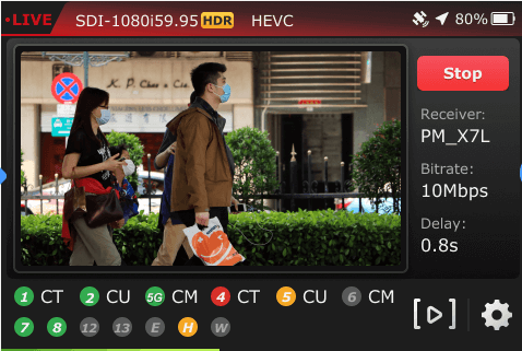
The camera icon and “Progressive Download” in the control bar are red when live with a receiver.
Note: The marked clips will not be transmitted during live streaming.
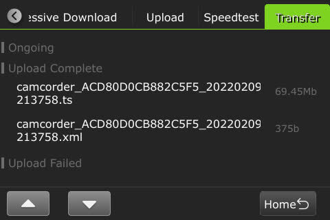
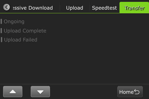
Tap the gear icon, then tap the Transfer tab to check the status and completion percentage on the transfer interface. Clips in the Ongoing list have not been processed.
Tap the Home button to return to the Progressive Download interface.
Tap the camera icon.
When the live stream has stopped, tap the Stop button.
Swipe the Slide to stop live slider. The transfer will start automatically.
When the live stream stops, the camera icon is no longer red. The previously marked segment has now been transferred.
Tap the gear icon
Tap the Transfer tab, your clip moves into the “Upload Complete” list.
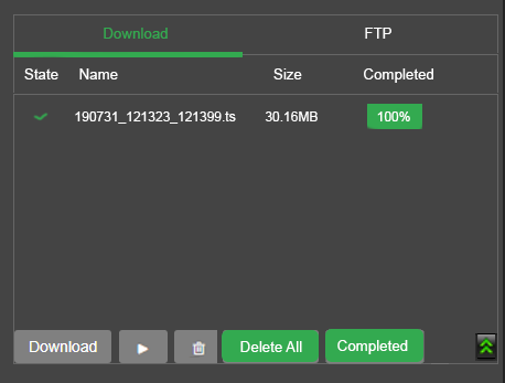
Your clips will automatically display in the download list on the receiver side.
Disabling the Progressive Download feature
There are two ways to disable the Progressive Download feature.
From the Settings menu.
From the Advanced configuration window.
To disable the Progressive download feature from the settings menu:
Tap the Gear icon.
Tap the Progressive Download tab.
Make your “Control” selection(s)(e.g.) Camcorder or Pack.
Note: Tap the Upload tab to change the receiver.
Move the Enable slider to the left. The slider will display gray when disabled.
Tap OK.
To disable the Progressive Download feature from the One‘s Advanced settings:
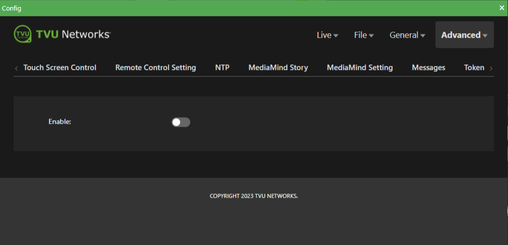
Tap the top Advanced menu and the Progressive Download tab.
Move the Enable slider to the left until it turns gray.
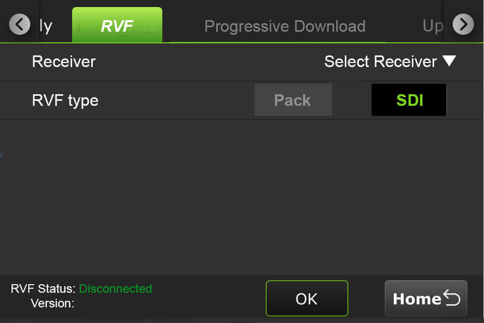
RVF tab
The return video feed type setting is accessed from the RVF tab.
Tap the RVF tab.
Select a receiver from the drop-down menu and select the RVF type. Then, tap the OK button.
Tap the Home button to return to the RVF control screen.
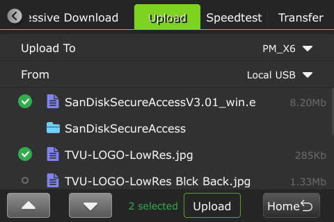
Upload tab
To upload files from a USB flash drive to a Receiver:
Tap the gear icon to open the Settings window, then tap the Upload tab.
Select a receiver from the “Upload to” drop-down list. Then, select a USB source in the “From” drop-down list.
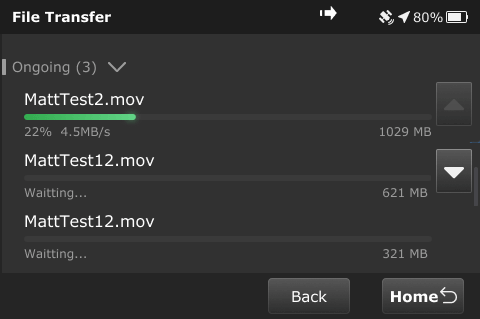
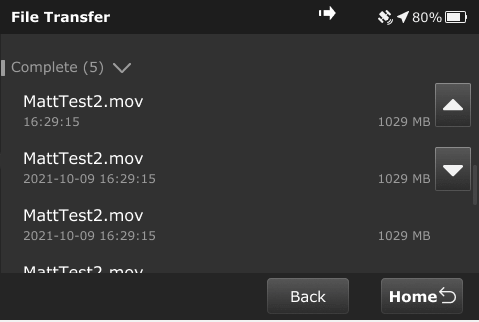
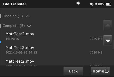
Transfer tab
To view file transfer status, including progressive download, download, and Auto Sync, complete the following steps:
Tap the Transfer tab.
The following prompt displays when the file is being transferred when shutting down. The File Transfer window displays.
File transfer in process:
File transfer complete:
File transfer ongoing:
The following dialog displays if file transfers are in progress when powering off the device.
Chapter 6 – Advanced configuration
This chapter explains advanced configuration procedures.
The One hotspot features
Wireless monitoring and control
A smart device can monitor and control the One transmitter wirelessly by connecting to the One’s hotspot. There are two hotspot connection methods available:
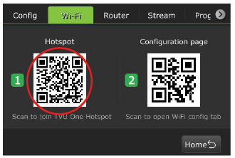
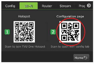
Scanning a QR code
Entering the network name + password login
The One status monitoring and control using a Web browser, iPhone, or smart mobile device
The TVU Transmitter’s operational status can be monitored, and various transmissions can be controlled from a Web browser. This interface can be accessed using a standard web browser connected to the One’s hotspot USB port on the side panel.
Connecting the One to the internal hotspot
Complete the following procedures to configure the One to the internal hotspot using your iPhone or smart mobile device:
Configuring the One transmitter for hotspot (optional)
Search for the hotspot on your iPhone/smart device. Then, when prompted, enter the case-sensitive SSID:
TVUPACK_XXXX (Where X is the last 4 digits of the transmitter’s PID) The default password is the last 8 digits of the transmitter’s PID
Note: All password characters are uppercase. The password can be changed in the Web UI if desired.
Connect to the SSID using your iPhone/smart device. Refer to the following examples of how the status screens display on a smart device Web browser.
Once the connection is established, you can open a web browser and enter https://192.168.4.1 in the address line to see the One’s system status.
Connecting to the hotspot using the QR code method
To connect to the hotspot by using the QR code, complete the following steps:
Tap the gear icon to open the Settings screen.
Tap the Wi-Fi tab.
Use your smart device to scan the Hotspot QR code.
Note: Connection is automatic; a password is not required when using this method.
Once the connection is established, scan the Configuration page QR code. This will display a Web page containing the One’s status and settings.
When connected to a GPS device or Partyline session, icons display at the top of the status screen next to the battery status.
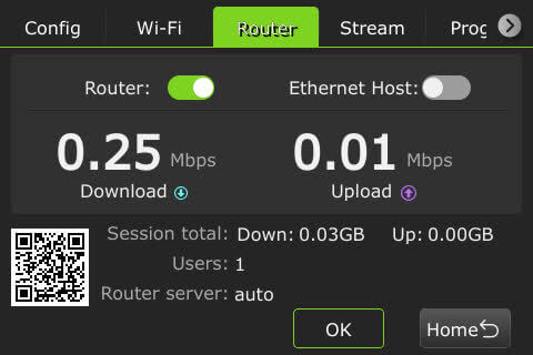
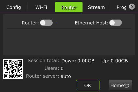
Router setting
To access the Router settings, complete the following steps:
Tap the gear icon to open the Settings screen.
Tap the Router tab. If the router setting is in the ON position, the following screen will be displayed.
If the router setting is OFF, the following screen displays.
TVU Router feature (client connections)
If higher bandwidth is required when using a hotspot, the optional TVU Router feature can be enabled to allow speeds of up to 200 Mbps to clients connected to the transmitter.
In the General > Network tab LAN Settings status panel Router menu, select Auto to enable the Router.
Enter the IP address and Subnet Mask. Then click Apply.
To confirm your settings, connected Clients are displayed in the Hotspot panels’ Connected Clients device list.
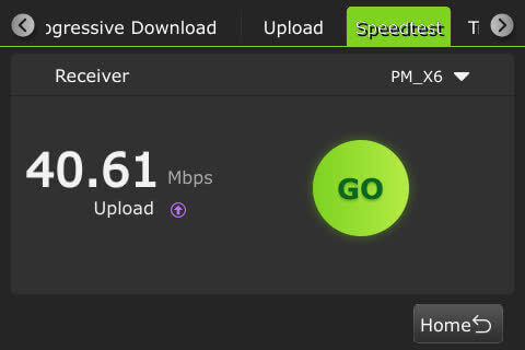
Speedtest feature
The Speedtest tab in the Settings menu allows the user to test the speed between the transmitter and receiver.
RVF
The built-in HDMI output for HDMI provides up to 1080p resolution and allows a user to send a confidence monitor or SDI source back to crews in the field. This on-board feature can now support viewing the return video feed using an iPhone and iPad.
Forced 3G/4G mode
When the forced 3G/4G mode is active, a padlock icon displays in the Modem setting window.
Timelock function enhancement
A Timelock icon displays in the top bar to indicate when the function is active.
Partyline function indicator
When a Partyline session is active, the Partyline icon displays in the top bar. Partyline Integrates with remote video conferencing as a One source. The TVU One can also send RTIL streams to Partyline as a TVU device.
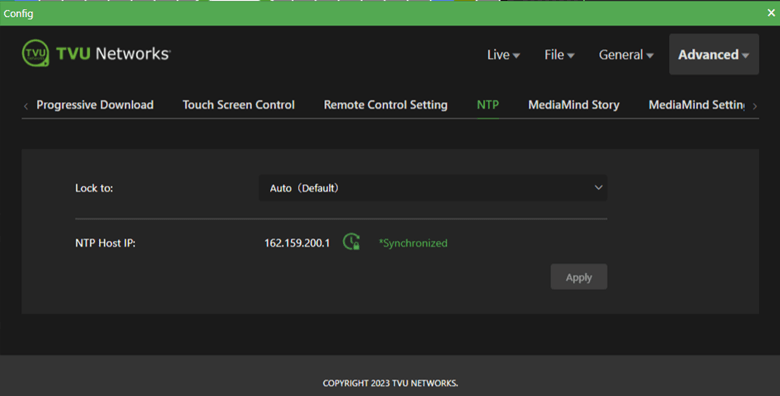
NTP host status feature
Users can access the NTP host status feature from the touchscreen display and the Web configuration page.
Advanced Web interface design and features
The v8.0 and later Web interfaces have the following new configuration panel design and added features, allowing users to easily set up, monitor, and manage settings from a simple Web interface.
You can access the One’s Web UI via the built-in hotspot, Command Center, and/or WebR on the receiver.
Frequently used WiFi, hotspots, modems, and Ethernet configurations have dedicated shortcuts.
Monitor the input on the touchscreen.
Start/stop and configure the stream.
Timelock technology ensures all sources are fully frame-synced automatically.
Use the Advanced Web interface to select the Live, File, General, and Advanced top menus for easy access to the following configuration pages:
Live menu
Click Live > Encoder tab to configure video, audio encoding, and audio output mapping.
Click Live > Receiver tab to configure receivers.
Click File > IP Source tab to add/view IP sources.
File menu
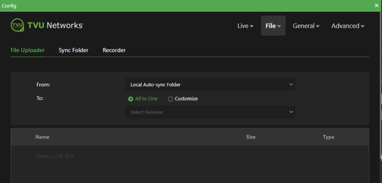
Click File > File Uploader tab to choose where you want to upload files from and where to.
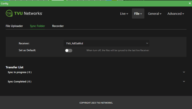
Click File > Sync Folder tab.
Use the Sync folder tab to transfer and sync files to a specific receiver. Refer to the topic “Auto Sync feature” for more information.
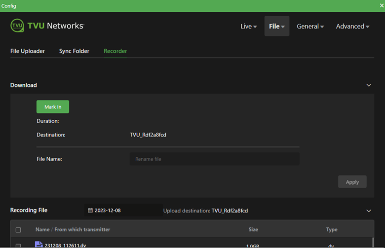
Click File > Recorder tab.
The Recorder tab allows users to select, mark, download, rename, and upload recorded files. Refer to the topic “Working with recorded content” for more information.
Users can Monitor the upload and export file status.
General menu
Click General > Network > LAN Settings.
In the General Network tab, users can configure their LAN Settings.
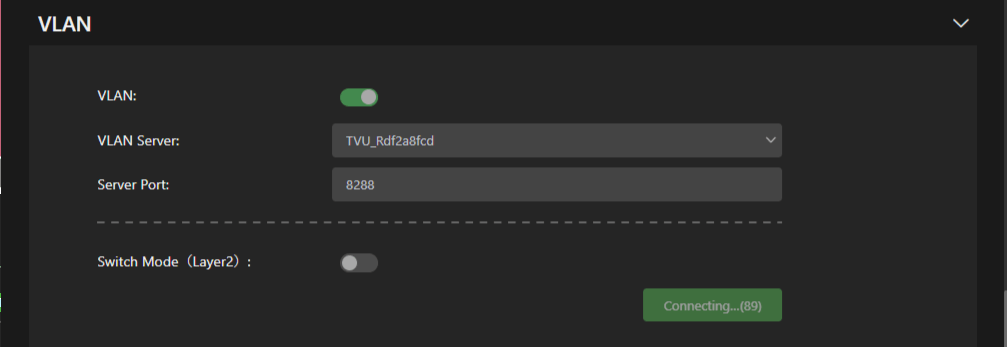
Click General > Network > VLAN.
The VLAN mode feature connects to the receiver’s VLAN without having a router data plan.
Click General > Network > Hotspot.
Hotspots for client connections can be configured in the Hotspot panel.
Click General > Network > WiFi.
Users can create additional WiFI connections with additional USB WiFi adapter support. Users can enable or disable WiFi from the UI. The WiFI will automatically redial if network connectivity fails.
Click General > Network > Ethernet.
Click General > Network > Modems.
Click General > Network >Firmware upgrade.
Users can check for firmware updates in the Firmware Update panel. The following message will appear when no firmware update is available.
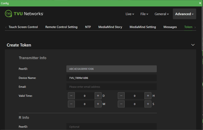
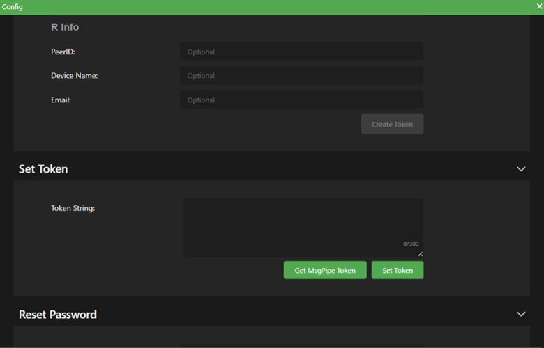
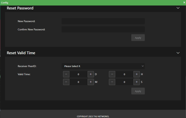
Click Advanced > Token tab to Create, Set, and Reset token passwords.
Chapter 7 – File-based workflows
This section provides information and instructions for file-based workflows. Topics include dual-encoder operations, Auto Sync, using the recording function, file upload feature, and Download feature.
Dual-encoder feature
The optional TVU dual-encoder feature records a pristine, high-resolution copy of all detected video directly to the external SSD storage. Thus, no video is lost, even if the original transmission encountered difficulties.
The TVU One transmitter continuously records a high bit rate using a second encoder. The second encoder Is always on when the unit is powered and does not require manual configuration or power.
A remote operator can then view and extract recorded content from the TVU Transmitter remotely using the receiver download feature.
In addition, the local TVU operator can access the recorded content for editing purposes.
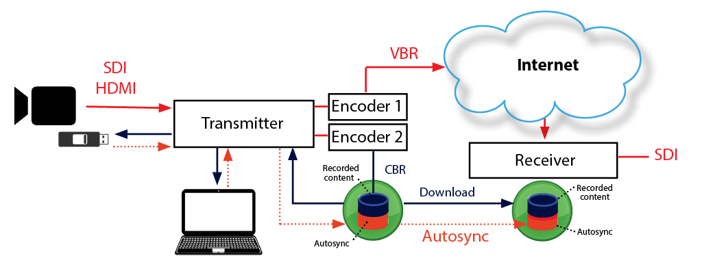
Auto Sync feature
Auto Sync is a high-speed file transfer feature that automatically pushes the files from the transmitter to the receiver using IS+.
There are two Auto-sync methods you can use to send files to the TVU receiver automatically:
You can perform Auto sync by inserting a USB stick into the transmitter.
You can use the TVU transmitter wireless hotspot feature to transfer files directly to the TVU transmitter for upload.
Using the Auto Sync feature with a hotspot (PC)
Complete the following steps to perform an Auto-sync file transfer using a wireless hotspot:
Search for the hotspot on your laptop or smartphone. The SSID will be TVUPACK_XXXX. (Where X is the last 4 digits of the TVU transmitter PID)
Connect to the SSID
The password is the last 8 digits of the transmitter’s PID. (Note: All characters are uppercase)
Once the connection is established, obtain the IP address in the Connection Details.
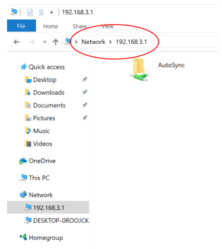
Open File Explorer, select Network and enter the IP address. For example \\192.168.4.1
The Auto Sync folder is displayed (as shown in the following graphic). Drag-and-drop the files to be transferred into the Auto Sync folder.
Using the Auto Sync feature with a hotspot (Mac)
Complete the following steps to perform an Auto-sync file transfer using a wireless hotspot:
Search for the hotspot on your laptop or smartphone. The SSID will be TVUPACK_XXXX. (Where X is the last 4 digits of the TVU transmitter PID)
Connect to the SSID
The password is the last 8 digits of the PID of the backpack (Note: All characters are uppercase)
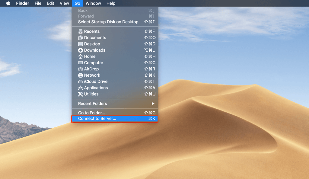
Go to Finder and select Connect to Server under the “Go” tab.
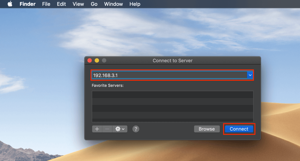
Enter “192.168.4.1” in the “Server Address” field and click Connect.
The “Connect As” pop-up menu displays. Select Guest and then Connect.
Move files you wish to be sent using TVU Auto Sync to the “AutoSync” shared drive icon on your desktop.
Using the Auto Sync feature with a USB stick
The Auto Sync feature allows you to transmit wireless digital content from the TVU transmitter to the TVU receiver using a USB memory stick.
The TVU transmitter will auto-detect the memory stick and automatically transfer the contents to its internal SSD hard drive. The content will then be available for wireless transmission to the TVU receiver.
Attention: The supported disk format is FAT 32 only.
To perform an Auto Sync using a USB memory stick to the One transmitter, complete the following steps:
Create a directory named “Auto Syncimport” in the memory stick.
Copy the content you want transferred into the “Auto Syncimport” directory.
Plug the memory stick into any spare USB port on the transmitter.
Monitor the file upload status on the TVU transmitter’s LCD screen. Do not unplug the USB memory stick during the file upload, as this may cause the system to malfunction.
Note: The TVU transmitter cannot be “live” to use this function.
Accessing stored content
Local Download of Recorded Content to a USB Memory Stick:
Connecting a USB memory stick (FAT 32 only) to a TVU transmitter while the video source is disconnected will transfer the entire video content of the last session to the memory stick in an NLE-compatible format.
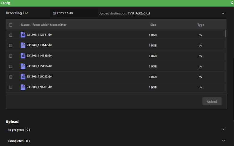
Additionally, on the web-based monitoring and controls interface, the Recording screen (explained in this section and “Working with recorded content”) will list the recorded sessions on the TVU transmitter SSD that are available for download and explain how to use the following three functions that are available in the Recording screen:
Export and play
Upload
Mark in and Mark out
Export and Play functions:
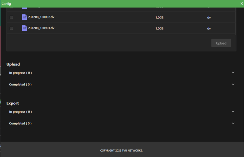
The Export function allows the user to extract recorded clips listed in the recording screen from the transmitter to a local USB drive. To use the Export function, complete the following steps:
Click the File drop-down menu and select the Recorder tab.
Select the check box next to the desired recording(s).
Click the Export button. Users will be warned if not enough space is available on the memory stick.
Select a clip from the list to preview recorded content and click the Play button.
Note: Playback is only available on iOS devices
Once a file has been selected to download to the USB, a “Copying” message will display while the file is copied, and a “Complete” message will display when the process is complete.
Note: The TVU transmitter cannot be “live” to use this function.
Upload function
The Upload function in the File > Recorder tab will use the “Auto Sync feature” to push recorded clips from the transmitter to a remote receiver. Refer to the topic “File Uploaded feature” for more information.
Working with recorded content
Mark In and Mark Out function
The Recording screen’s Mark In and Mark Out functions explicitly select a portion of a live ingest for extract or upload.
Complete the steps in the following procedure to use the Mark In and Mark Out functionality in the File > Recorder tab to isolate and copy a live video clip to a USB thumb drive or to upload directly to a receiver using the Recording status window:
Note: The TVU device is always recording when it is powered on and a valid video source is connected.
Click the File drop-down menu and select the Recorder tab.
Click the Mark IN button to mark the IN point of a segment in the recorded video on the transmitter.
Click the Mark OUT button to mark the OUT point of a segment in the recorded video on the transmitter.
Note: After the IN and OUT points are identified, it is possible to play the clip, copy the clip locally to an inserted USB thumb drive, or upload it directly to the selected receiver.
Enter a specific name for the recorded segment in the File Name field.
Click the Apply button to add the recording to the recorded segment list at the bottom of the Recording status window.
To search for and display a recorded video segment by date, click the calendar icon at the top of the recorded file list and select a recording date to display the recording in the list.
To select and play a preview of a specific video recording in the list, click the check box next to the recording and click the Play button.
To copy a clip from the list to the transmitter, insert the thumb drive into the One’s USB port, click the recorded file check box in the list, and click the Export button.
Click the Upload button to transfer the copied recorded file from the transmitter to the default receiver (designated in the receiver window).
File Uploader feature
The TVU One Upload window allows you to upload files to a particular receiver using the “Auto Sync feature,”
Using the File Uploader panel
Complete the steps in the following procedure to select a specific receiver to upload files from:
Click File > File Uploader.
For each file uploaded, select the specific receiver to which you would like the files uploaded from the Select Receiver drop-down menu.
Once the receiver is selected, click the File > Sync Folder tab and select a default receiver from the drop-down menu.
To make your selection the default receiver, Move the Set as Default slider to the right until green. This will enable all future files to be uploaded to the default receiver.
Notes:
For instructions about uploading files from a TVU Transmitter to the TVU Receiver, refer to the “Auto Sync feature” topics “Using the Auto Sync File Transfer with a hotspot” or “Using the Auto Sync feature with a USB stick” for more information.
The TVU transmitter cannot be “live” to use this function.
Download feature
The download (pull) RX feature lets the operator see and extract recorded transmitter video remotely.
The download local transmitter (T) feature allows local access to recorded content for editing purposes.
Refer to the Server hardware guide for detailed information about the Download feature and its functionality.
Progressive download feature
The Progressive download feature allows real-time simultaneous download streaming from a file-based clip. This feature allows the operator to begin playback of the media before the download is complete.
Note: When delivering using the progressive download feature, you can encode at higher variable bit rates than with streaming.
To use the Progressive download feature, complete the following steps:
To start the progressive download feature, click the Advanced > Progressive Download tab.
Move the Enable slider to the right until green. Then select a Control method radio button.
For Camcorder control, press the Record button on the camcorder. For the transmitter (Pack), tap the play [>] button to enter the control page to mark the files’ In/Out parameters. The receiver is specified in the File > Sync folder tab.
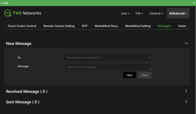
Messages feature
The Messages feature allows users to send messages between the transmitter and receiver.
Complete the following steps to send a message to another transmitter or receiver:
Click Advanced > Messages.
In the “To” field, enter the recipient’s TVU receiver or Ones’ PID.
Enter your message in the Message: field and click the Send button.
Notes: 1. Expand the Received Message panel to view messages that were received by the transmitter.
2. Expand the Sent Message panel to view messages that were sent by the transmitter.
Audio channels
The Audio channels window lets you switch audio between 4 and 8 channels.
Note: The One transmitter running version 8.0 and higher allows 2, 4, and 8-channel switching.
Complete the following steps to update the audio switching setting:
Click Live > Encoder tab and expand the Audio Encode panel.
Select the audio channel radio button you desire.
Upgrade firmware
Users can upgrade the embedded radios to the latest firmware using the Firmware upgrade panel.
Complete the following steps to upgrade the firmware version:
Click General > Firmware Upgrade.
Follow the online instructions. A confirmation message will appear if your firmware does not need to be upgraded.
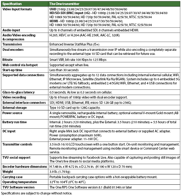
Chapter 8 – Product specifications – Model TM1100 transmitter
["TVU Command Center User Guide","TVU One TM1000v3 FHD and 4K Hardware Quick Start User Guide","TVU One TM1000v3 FHD and 4K Software Quick Start User Guide","TVU Home Quick Start User Guide","TVU RPS Link Encoder Model TE5700 Hardware Setup Guide","TVU RPS Link Encoder v6.7 Software Setup Guide","TVU RPS VS3500 Hardware Setup Guide","TVU RPS VS3500 Software User Guide","TVU Servers Linux v8.4 Hardware User Guide","TVU Servers Linux v8.4 Software User Guide","TVU RPSVS3600 Multi-Channel Software User Guide v8.1","TVU Remote Commentator Quick Start Guide","TVU Partyline Quick Start User Guide","TVU Anywhere Quick Start Guide","TVU Producer Quick Start User Guide","TVU Producer Advanced Audio Mixer User Guide","TVU MLink TE5500 v7.4 and TE5800 v8.0 User Guide","TVU RPS One Model TM1100 Software QSUG v8.3","TVU One Model TM1000v4 Software QSUG v8.3","TVU RPS One Model TM1100 Hardware QSUG v8.3","TVU One Model TM1000v4 Hardware QSUG v8.3","TVU RPS One Model TM1100 Software QSUG v8.2","TVU MediaHub Quick Start User Guide","TVU Home User Guide (Beta) version","TVU Review Quick Start User Guide","TVU Replay Quick Start User Guide","TVU Servers Linux v8.3 Software User Guide","TVU Servers Linux v8.3 Hardware User Guide","TVU Router Portal Quick Start User Guide","TVU Media Analyzer Quick Start User Guide","TVU MLink TE5500 and TE5700 User Guide v7.4","TVU Anywhere Lite Fast Track Guide","TVU POWERPAC and POWERPAC 2 Quick Start User Guide","TVU Servers Linux v8.2 Software User Guide","The One Model TM1100 Software Quick Start User Guide","TVU Servers Linux v8.2 Hardware User Guide","TVU Timelock Quick Start User Guide","TVU One Model TM1100 HDMI RVF Quick Start User Guide","The One Model TM1100 Hardware Quick Start User Guide","TVU Producer Advanced Audio Mixer User Guide","TVU Servers Linux v8.1 Software User Guide","TVU Servers Linux v8.1 Hardware User Guide","The One Model TM1100 Software User Guide","TVU Nano Router (5G) Model RD300 Setup and User Guide","TVU Rack Router 5G Hardware Setup and User Guide","TVU MLink TE5500 and TE5700 User Guide","TVU G-Link Software feature User Guide","How to configure TVU Channel settings tutorial","TVU Servers Linux v7.9 Hardware User Guide","TVU Servers Linux v7.9 Software User Guide","How to add an HLS output in TVU Channel","How to add an ISSP output in TVU Channel","How to add an SRT output in TVU Channel","How to go live with HLS to VLC in TVU Channel","How to show, hide, create, and delete folders in TVU Channel","How to add an RTMP output in TVU Channel","How to add a UDP output in TVU Channel","How to add an RTSP output in TVU Channel","How to add a Facebook output in TVU Channel","How to add a Yi Live output in TVU Channel","How to add a Twitter output in TVU Channel","How to add a Twitch output in TVU Channel","How to add a KuaiShou output in TVU Channel","How to output a Generic IP stream in TVU Channel","How to use the emergency switch function in TVU Channel","How to use TVU Transcriber\/CC in TVU Channel","How to configure TVU Channel Settings in Workbench","How to use keyboard shortcuts in TVU Channel","How to create a new channel in TVU Channel","How to change TVU Channel Settings in Workbench","TVU Channel User Guide","TVU Servers Linux v7.8 Software User Guide","TVU One Li-ion Battery Safety and Use Guidelines","TVU Grid for Command Center Quick Start User Guide","TVU Command Center File-Based Workflows User Guide","TVU Grid Token Quick Start User Guide","TVU Anywhere Token Quick Start User Guide","TVU Servers Linux v7.8 Hardware User Guide","TVU Search Quick Start User Guide","TVU Transcriber Feature Guide","TVU POWERPAC Quick Start User Guide","How to tag participants in TVU Partyline","Where to learn about TVU Partyline updates and latest features","How to use the vertical video feature in TVU Producer","How to add video transitions in TVU Producer","How to use voice over IP (VoIP) with the TVU Anywhere app","How to use token pairing with TVU Anywhere","How to use TVU One Wired Remote Control","How to output to IP destinations in TVU Search","How to post a clip to Social Media in TVU Search","How to select templates when sharing clips in TVU Search","How to upload a facial image to find content in TVU Search","How to use facial selection to find the speech in TVU Search","How to select text to create a clip in TVU Search","How to create Grid tokens to share Grid feeds in TVU Command Center","How to use the Talkback feature in TVU Remote Commentator","How to add Singular Live graphic overlays in TVU Channel","How to add a Zixi output in TVU Channel","How to add a ProMPEG output in TVU Channel","How to add a YouTube output in TVU Channel","How to manage your program Schedule in TVU Channel","How to upload and verify media in TVU Channel","How to add and schedule live sources in TVU Channel","How to create a Program Template with SCTE markers in TVU Channel","How to delete and duplicate a program or media in TVU Channel","How to use the program settings window TVU Channel","How to move or drag and drop media into the TVU Channel Scheduler","How to create a Program Template in TVU Channel","How to create a Schedule Template in TVU Channel","How to change a live input source or program duration in TVU Channel","How to remove and replace live programs in the TVU Channel Playout window","How to add backgrounds and logos in TVU Partyline Kiosk mode","TVU Remote Commentator – How it works","How to use the Coordinator room in TVU Remote Commentator","How to use the commentator view in TVU Remote Commentator","How to invite commentators to join an event in TVU Remote Commentator","How to add commentary groups to an existing event in TVU Remote Commentator","How to change the backup input source in TVU Remote Commentator","How to switch to a backup feed in TVU Remote Commentator","How to set up a backup source in TVU Remote Commentator","How to create an event in TVU Remote Commentator","How to use the change layout function in TVU Partyline","How to use screen sharing as a host in TVU Partyline","How to use the Kiosk mode in TVU Partyline","How to use screen sharing as a participant in TVU Partyline","How to ingest IP video sources into TVU Producer","How to configure participant settings in TVU Partyline","How to add a Local video source in TVU Producer","How to add a Partyline feed in TVU Producer","How to use the clip recording feature in TVU Producer","How to add HTML video sources into TVU Producer","How to set up IFB and VoIP on a TVU receiver","How to use the “Take Next” feature","How to take your channel to Air","How to add and execute crawls","How to add a graphic logo overlay","How to break into and rejoin programming","How to build live and recorded program templates","How to schedule a program","How to duplicate\/repeat programs and program templates","How to create a Channel","How to add pre-recorded programs","How to add SCTE triggers to your program schedule","How to create and add schedule templates","How schedule live events","How to import and export the Programming Guide","How to enable Closed Captioning (CC)","How to use the TVU Command Center mobile App. For iOS","How to start TVU Partyline as a host","How to use Split Screen or Picture-by-Picture (PBP) with TVU Anywhere app.","How to integrate a Singular Live and graphic URL into TVU Producer","How to use the overlay feature in TVU Producer","How to use the pull or push feature with RTMP sources in TVU Producer","How to use Return Video Feedback (VFB) with the new TVU Anywhere user interface.","How to use replay in live productions with TVU Producer","How to use TVU Partyline for remote collaboration and conferencing for live video production","How to add a custom Dual and Quad-view video effect in TVU Producer","How to use TVU One Progressive Download mode","How to extend the battery life of a TVU One using the TVU POWERPAC Li-ion external battery.","How to conduct port tests with Linux v7.5 and 7.6 receiver software","How to use the Picture-in-Picture feature in TVU Producer","How to use the Picture-in-Picture (PiP) in TVU Partyline","How to use Picture-in-Picture (PIP) to play recorded video into the live stream, with the new TVU Anywhere user interface.","How to output multiple audio channels in TVU Producer","How to use the monitoring panel in TVU Producer.","How to lock and rename participants in TVU Partyline","How to join TVU Partyline as a participant","What is ISO Recording? Does TVU Producer support it?","How to use the group and private chat feature in TVU Partyline","How to use the full-screen feature in TVU Partyline","How to enable VLAN Service with the Linux v7.5,7.6 receiver software","How to add multiple custom views and borders in TVU Producer","How to use the remote collaboration feature in TVU Producer","How to use the clear overlay and remove overlay features in TVU Producer","How to add graphic overlays in TVU Producer","How to add a Grid source into TVU Producer","How to add a TVU One source into TVU Producer","How to add a TVU Anywhere app source into TVU Producer","How to add paired TVU Anywhere sources in TVU Producer","How to use the TVU One 4-Channel Encoder"]


 icon to enter the control page to set your mark in/out preferences.
 icon is red when a Progressive Download is in progress.
 icon is red when the transmitter is live with a receiver.
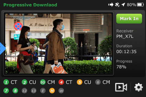
 icon displays in the status bar. The file duration displays below the Mark out button.