Contents
- Introduction, setup, and base operation
- Features overview
- TVU RPS Web interface
- Network requirements
- Router and firewall configuration
- Front and rear panel overviews
- Setup procedures
- RPS transmitter (encoder) identification and setup procedure
- RPS receiver (decoder) identification and setup procedure
- RPS encoder server settings
- Establishing an Internet connection
- VLAN and VoIP configuration
- NTP configuration
- Output video format
- RPS decoder server settings
- Hardware configuration options
- Product specifications
- Applications overview
TVU RPS Hardware Setup Guide
The TVU multi-channel RPS is a remote solution for at-home production/REMI (Remote Integration Model) production. TVU offers the only cost-effective RPS solution for frame-accurate, synchronized, multi-channel production over the public internet in the broadcast industry. Capture content live from any remote location and produce it instantly from your studio.
Introduction, setup, and base operation
Traditional video production requires on-location trucks and large production crews, which are costly and complicated to manage. TVU Remote Production Solution (RPS) delivers the same high standards as a traditional broadcast setup while reducing personnel and equipment on location.
TVU RPS perfectly synchronizes live video feeds from the venue and sends them to your studio for frame-accurate, genlocked live production. RPS live multi-channel synchronization works as a remote production encoder and decoder.
Within one single rack unit encoder at the venue and one rack unit decoder at the studio, you can connect up to eight live video feeds, sending up to six live Full HD transmissions with two high-quality video return feeds.
With TVU Remote Production System (RPS) and TVU Timelock, you can produce a professional quality video from up to six channels from the comfort of your facility, regardless of your network connection or whether your cameras are fixed or on the move.
Product overview
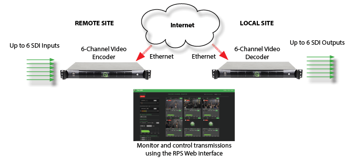
TVU RPS consists of a transmitter and a receiver. The RPS transmitter encodes up to six synchronized SDI sources. It transmits high-quality, low-latency IP video from the remote location to a studio-based TVU RPS receiver, which decodes six accurately synchronized SDI outputs. RPS’s user-friendly interface grants control over all aspects of transmission, including bitrate and latency, and provides previews of all four channels with the Duo 2 card and all six channels with the Quad 2 card.
TVU RPS also provides up to two low-latency return video feeds sent from the studio back out to the field. VLAN tunnels on RPS decoders enable communication between the studio and the field over a private network.
Features overview
- Supports TVU Switch via VLAN Tunnel (Layer 2 connectivity). Users can now switch between standard VLAN tunnel and TVU Switch based VLAN tunnel.
- Transmit to RPS decoder and Producer simultaneously.
- Support for VBR and VBR Channel Priority transmitting to Producer or multiple decoders.
- Support for CC708/608 embedded captions transmission.
- Supports up to six fully synchronized multi-channel transmissions. Supports the 6-channel Quad 2 and 4-channel Duo 2 cards.
- Dependable, fixed, low-latency transmission over standard-contended Internet connections.
- Includes multiple encode behaviors to suit virtually any network environment.
- The RPS sends metadata and control from the studio to the field using a VLAN Tunnel.
- Support for return feeds and up to 16 channels of audio per SDI input.
- Compatible with TVU Producer 3.0, our cloud-based video production solution, to manage remote broadcasts from any location.
- A high-quality, low-latency video feed of the live program from the station via HDMI. Up to two low-latency return video feeds sent from the studio back out to the field.
- The RPS encoder easy-to-use browser interface that is accessible using the TVU RPS Web interface or your TVU Command Center account.
- Supports the restart option for users.
About this guide
This user guide will enable you to:
- Describe the contents and key features of the TVU Remote Production System.
- Explain the primary function of the TVU RPS.
- Identify the TVU RPS encoder and decoder hardware.
- Describe the TVU RPS encoder and decoder components and connections.
- Set up the TVU RPS VS3500 encoder and decoder hardware.
- Configure the RPS server IP address.
- Configure the RPS encoder and decoder ports.
- Log into the RPS Web interface.
Contents
TVU RPS includes the following 1RU rack-mount Model VS3500 servers:
- One VS3500 transmitter (encoder)
- One VS3500 receiver (decoder)
- 18x 2.3 DIN to BNC male adapter cables, BB or Tri-level (BNC adapter)
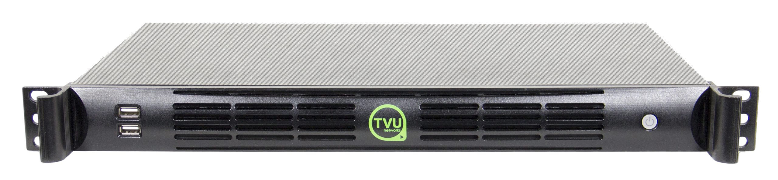
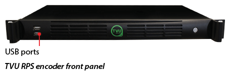
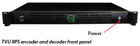
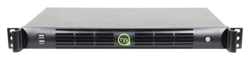
TVU RPS Model VS3500 transmitter and receiver
The TVU RPS encoder and decoder share the same basic hardware platform. The front panel features a button to power on the unit.
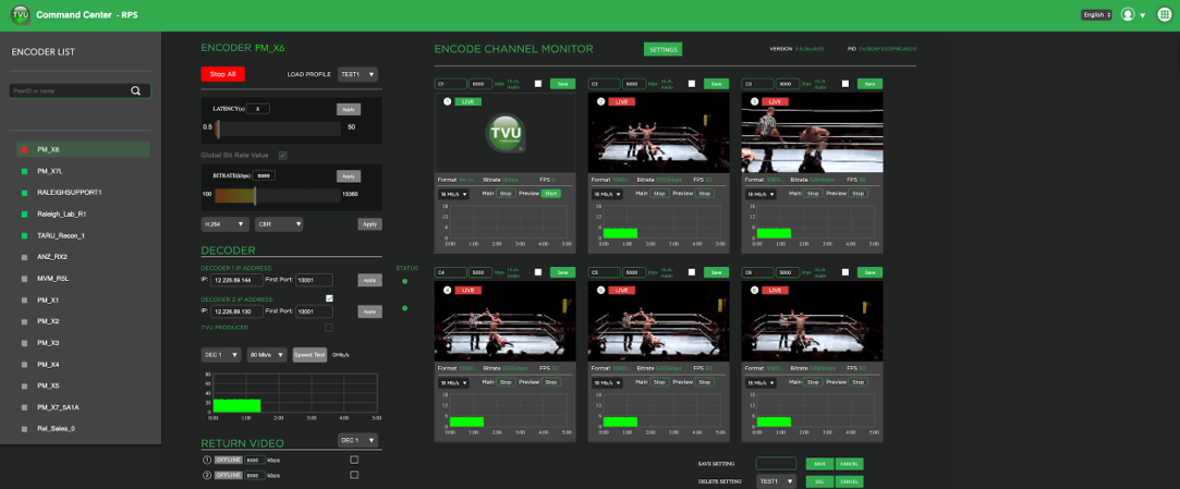
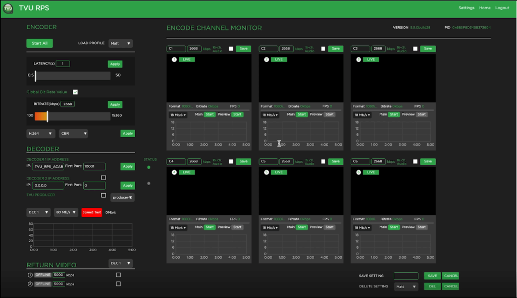
TVU RPS Web interface
After the unit is set up and powered on, monitoring and control of the system is performed with the TVU RPS Web interface which is hosted on the encoder. This interface is also accessible through the Command Center user interface.
You will use the TVU RPS Web interface to monitor and control all aspects of transmission, including real-time previews, current bitrate, and latency of all four channels with the Duo 2 card and all six channels with the Quad 2 card.

For more information about setting up the RPS VS3500 with the 4-channel Duo 2 card, refer to “Hardware configuration options.”
Network requirements
TVU Networks® recommends that you assign a static IP address to the RPS decoder to ensure the network configuration remains stable.
Important: Contact TVU Networks support if you want to use a configuration other than the one specified in the this hardware set up guide.
Router and firewall configuration
Complete the following steps to configure your router or firewall:
- Permit all UDP incoming traffic for port 10001 at the receiver (video).
- Permit both TCP and UDP incoming traffic for port 10010.
- Permit TCP incoming traffic for port 10009.
- Permit all UDP incoming traffic for port 6532 at the receiver (VLAN Tunnel).
- For VoIP services, permit outbound traffic to ports 9001, 9091.
- TVU recommends using a public IP address for the encoder. If a public IP address is not possible on the encoder side, you must open and forward port 80 (TCP) to access the web GUI remotely.
- Depending on the selected bitrate, encoding streams may require as much as 15 Mbps for each stream. TVU recommends having at least 100 Mbps of bandwidth when using 6 streams. If less bandwidth is available, lower the encoding bitrate (using the encoder web GUI) or reduce the number of channels. TVU Networks also has solutions to aggregate multiple IP connections to provide increased throughput. Please contact TVU for further information.
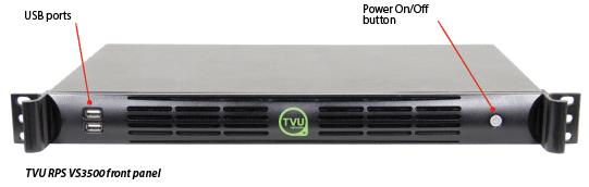
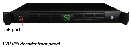
Front panel overview
The TVU RPS VS3500 encoder and decoder front panel feature two USB 2.0 ports and the power on/off button.
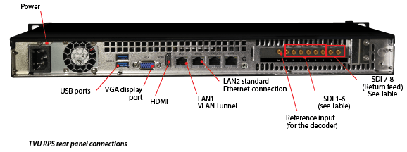
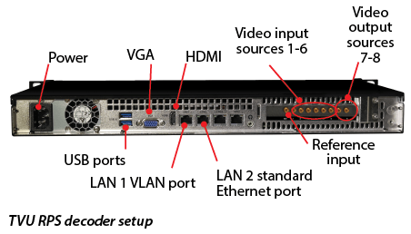
Rear panel overview
The TVU RPS VS3500 encoder and decoder rear panel feature the following connections:
Quick Start guide
This user guide provides instructions to complete the following procedures:
- Setting up the TVU RPS VS3500 encoder and decoder
- Setting up the RPS server IP address
- Configuring the RPS encoder and decoder ports
- Logging in to the RPS interface
- Configuring the TVU RPS VS3500 encoder and decoder using the RPS Web interface
RPS server setup
The following hardware procedures will explain how to set up and identify your encoder and decoder hardware.
RPS transmitter (encoder) identification and setup procedure
The following procedure provides the steps necessary to identify and perform the initial setup for the RPS encoder with the 6-channel Quad 2 card.
Note: If your RPS server is using the 4 channel Duo 2 card refer to “Hardware configuration options.”
Complete the following steps to set up the TVU RPS VS3500 transmitter (encoder):
Note: All input sources must be the same video format and frame rate.
- Connect the factory-supplied power cable to the encoder.
- Connect a monitor to the encoder using the HDMI or VGA connections.
- Connect the VLAN cable to the VLAN 1 port for VLAN tunnel support. Ports marked “LAN1” (the left port) are later encoder models.
- Connect an Ethernet cable to the following Ethernet port: LAN2 (second from left) is for a standard Ethernet connection.
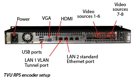
- Connect a keyboard and mouse to the encoder using the two front or rear panel USB ports.
- Connect a factory-supplied 2.3 DIN to BNC male adapter cable to the decoder reference input (if required).
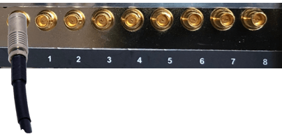
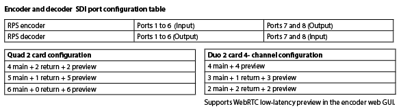
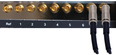
- Starting with port 1, connect 1 to 6 SD/HD-SDI video output sources to ports 1 to 6. Use the factory-supplied 2.3 DIN to BNC male adapter cables.
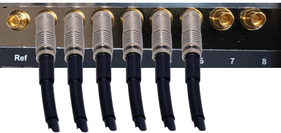
- Connect SD/HD-SDI return video sources to ports 7 and 8 for the return video. Use the factory-supplied 2.3 DIN to BNC male adapter cables.
RPS receiver (decoder) identification and setup procedure
Complete the following steps to set up the TVU RPS VS3500 receiver (decoder):
- Connect the factory-supplied power cable to the decoder.
- Connect a monitor to the encoder using the HDMI or VGA connections.
- Connect the VLAN cable to the VLAN 1 port for VLAN tunnel support. Ports marked “LAN1” (the left port) are later encoder models.
- Connect an Ethernet cable to the following Ethernet port: LAN2 (second from left) is for a standard Ethernet connection.
- Connect a keyboard and mouse to the decoder using the two front or rear panel USB ports.
- Connect a factory-supplied 2.3 DIN to BNC male adapter cable to the decoder reference input (if required).
- Starting with port 1, connect 1 to 6 SD/HD-SDI video output sources to ports 1 to 6. Use the factory-supplied 2.3 DIN to BNC male adapter cables.
- Connect the SD/HD-SDI return video sources to ports 7 and 8 for the return video. Use the factory-supplied 2.3 DIN to BNC male adapter cables.
- Verify that the encoder and decoder are connected as described in the encoder and decoder setup procedures. Then, power on both units.
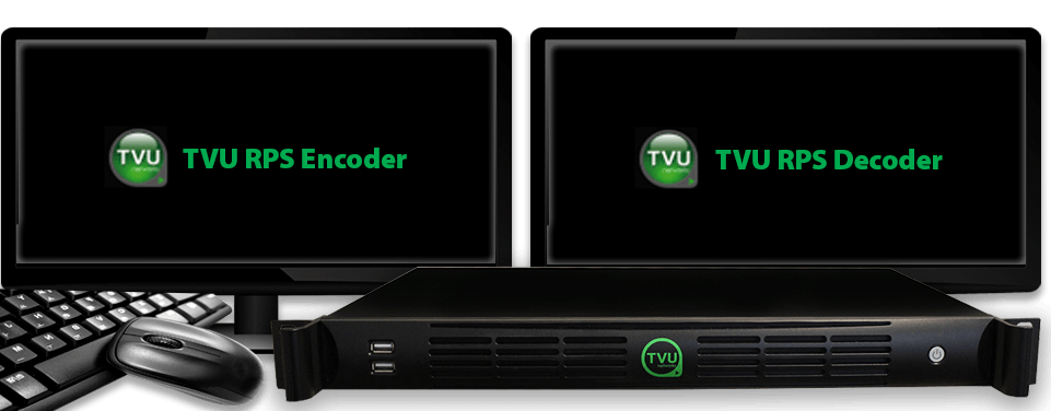
Note: During boot-up, the “RPS Decoder” and “RPS Encoder” splash screens display on their respective monitors.
TVU RPS encoder server settings
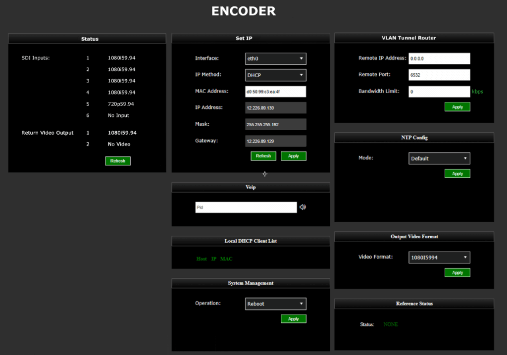
The encoder and decoder set up pages display with slightly different information. However, they accomplish the same goals and are accessible using the HDMI out connection, VGA connection, or a web browser. The encoder server settings screen displays after the encoder is powered on and the splash screen briefly appears.
You will use the TVU RPS Web interface to monitor and control all aspects of transmission, including real-time previews of all six channels, current bitrate, and latency.
Establishing an Internet connection
Notes:
- IP Addresses can be static or dynamically assigned (DHCP), and can be assigned to interface Eth0 which is used for primary RPS functionality, or assigned to Eth1, which is used for the VLAN tunnel.
- The physical ports Lan1 / Lan2 and logical designations Eth0 and Eth1, are reversed:
LAN2 = Eth0. Primary communications
LAN1=Eth1. VLAN tunnel functionality
To set up an internet connection for the encoder using a DHCP or static IP method, complete the following steps:
- In the Set IP pane, use the default interface settings ‘Eth0’ and ‘IP Method’ if you use DHCP. Click the Refresh button in the Set IP pane. The IP address, Mask, and Gateway fields should automatically populate.
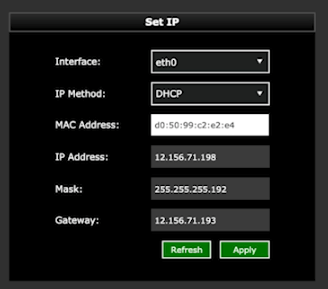
- If you use a static IP address, click the IP Method drop-down menu and select Static. Then, enter your desired IP address, Mask and Gateway.
- Click Apply to save your settings.
VLAN Tunnel configuration overview
By default, VLAN configuration automatically populates. In addition, the VLAN tunnel is designed to be a “set it and forget it” network between the encoder and decoder and distributes IP addresses accordingly using DHCP.
If the user would like to perform an advanced VLAN configuration, the VLAN tunnel settings can be used to network several devices that are connected to an encoder by using a local switch, or to view the encoder Web UI from the decoder network. The VLAN Tunnel supports IP Intercom, IP Tally, or CCU.
Subnet rules:
The IP addresses assigned to eth1 for each side of the VLAN tunnel must be on different subnets. The VLAN tunnel routes between networks.
For example:
- For the encoder, use: 10.20.0.1/255.255.255.0
- For the decoder, use: 10.30.0.1/255.255.255.0
VLAN Tunnel configuration
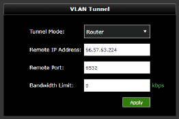
The VLAN Tunnel setting pane is used to configure the VLAN tunnel functionality by inputting the decoder’s IP address, port, and bandwidth limit (optional). The port is associated with 6532 by default but can be changed if desired. For more information, refer to the latest TVU port forwarding guidelines.
To change the VLAN tunnel (Router) settings, enter your change(s) in the VLAN tunnel pane and click Apply.
VoIP configuration
The VoIP settings pane allows the user to enter the decoder’s PID into the encoder’s VoIP settings pane to establish communication between the encoder and decoder.
To configure VoIP complete the following steps:
- In the VoIP pane, enter the full PID number of the encoder.
- Click the speaker icon to initiate the call.
TVU VLAN Tunnel Switch mode
The VLAN Tunnel Switch mode:
- Provides support for TVU Switch via VLAN Tunnel (Layer 2 connectivity)- User can now switch between standard VLAN tunnel and TVU Switch-based VLAN tunnel.
- Without network configuration, remote networking devices become true plug-and-play devices using TVU Switch. This allows the DHCP connectivity to work with any device when connected to the TVU Encoder or Decoder.
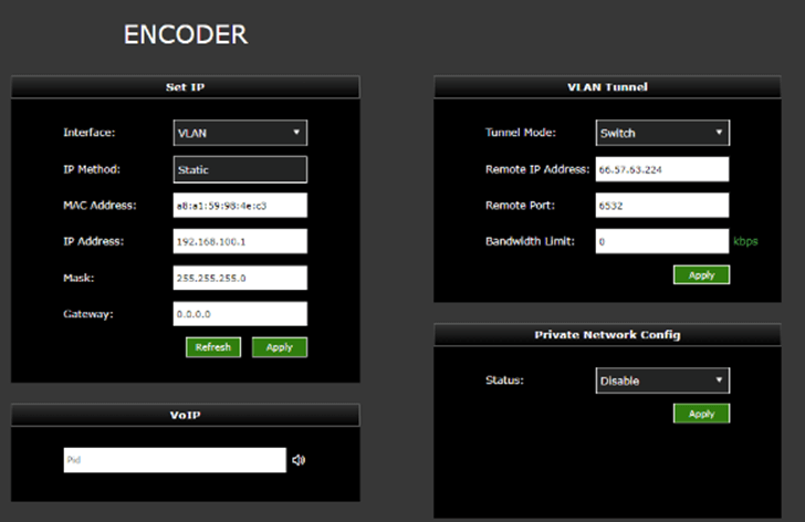
To configure VLAN Switch mode on the Encoder (router client):
- Open to the Encoder setup page. Select Switch from the Tunnel Mode drop-down menu in the VLAN Tunnel panel.
- Enter the Remote IP Address of the Decoder.
- Leave the Remote Port set to the default 6532 and click Apply.
- In the Set IP panel, allow the VLAN IP, Mask, and Gateway defaults as shown in the following “Encoder (router client) configuration” figure.
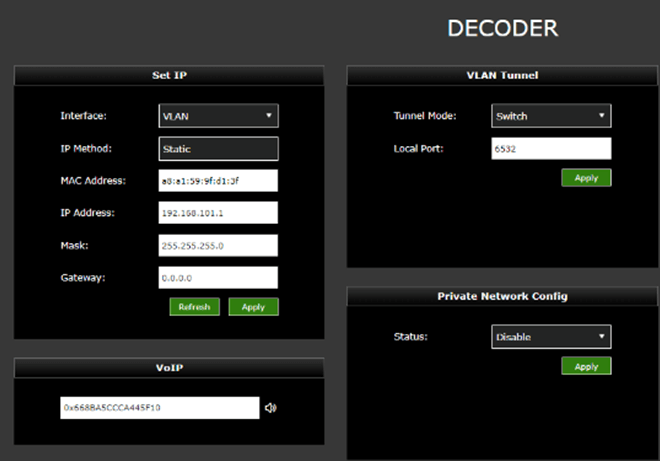
To configure VLAN Switch mode on Decoder (router server):
- Open the Decoder setup page.
- Select Switch from the Tunnel Mode drop-down menu in the VLAN Tunnel panel and click Apply.
- In the Set IP panel, assign the required VLAN IP, Mask, and Gateway as per your requirement and click Apply.
- In the Set IP panel, allow the VLAN IP, Mask, and Gateway defaults as shown in the following “Decoder (router server) configuration” figure.
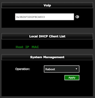
The Local DHCP client list in “Decoder (router server) displays the IP/MAC address of the clients connected to the Encoder and Decoder VLAN port.
VLAN Tunnel Switch Mode basic setup diagram
Note: When in Switch mode, the decoder is the DHCP server and the encoder is the router client.

Dual live decoder support
Using this method, the user can push the RPS Encoder streams to both Decoder 1 and Decoder 2 or Producer and Decoder 2.
When using TVU Producer, the user must select the check box next to TVU Producer, which will prompt the user to add the login and password for a producer VM session.
To support two live decoders simultaneously, complete the following steps:
- In the RPS user interface Decoder 2 IP Address settings panel, click the checkbox as shown in “Enable dual live decoder settings.”
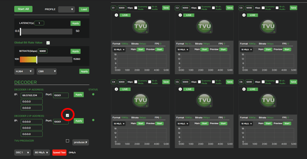
- Enter the Decoder 2 IP address and port number.
- Click Apply.
Closed Caption support
There is no specific setting in the RPS user interface for Closed Captions. The user must connect the closed caption source to the Encoder and Decoder to output the CC video in the output.
NTP configuration
The NTP configuration panel allows users to configure the encoder and decoder as local NTP servers in a closed network. If you use RPS in a closed network without internet access, you must use the “Customized” setting for NTP configuration.
To configure NTP, complete the following steps:
- Click the Mode drop-down menu in the NTP Config pane and select a mode.
- To customize the NTP Configuration mode, select Customized from the drop-down menu. Then, enter the Server IP address of the decoder and leave the Port number 123.
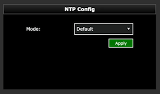
- Click Apply to save your settings.
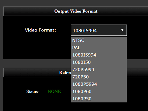
Output video format
The Output video setting panel allows a user to select the output resolution and framerate of all of the channels that are coming from the encoder.
In the Output Video format pane, select a Video format from the drop-down menu and click Apply.
TVU RPS decoder server settings
The encoder and decoder setup pages display slightly different information. However, they accomplish the same goals and are accessible using an HDMI out connection, VGA connection, or a web browser.
The decoder server settings screen displays after the decoder is powered on and the splash screen briefly appears.

Establishing an Internet connection
Notes:
- IP Addresses can be static or DHCP and assigned to interface eth0 which is used for primary RPS functionality, or assigned to eth1, which is used for the VLAN tunnel.
- The decoder IP address cannot be changed when VFB is enabled.
To set up an internet connection for the decoder, complete the following steps:
- If you are using DHCP, click the Refresh button in the Set IP pane. The IP address, Mask, and Gateway fields should automatically populate.
- If you are using a static IP address, click the IP Method drop-down menu and select Static. Then, enter your desired IP address, Mask and Gateway.
- Click Apply to save your settings.
Logging in to the TVU RPS Web interface
To log in to the TVU RPS Web interface, have your encoder static IP address available and complete the following steps:
Log in to the RPS Web interface
- Open a Web browser window and enter: http://IP_Address/rps/index.html
(Where IP_Address is your Encoder static IP address)
- Click Enter. The login pop-up displays.
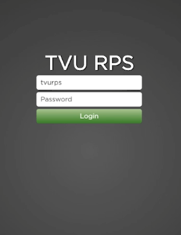
- To Log in to the RPS Web interface, Enter the following using all lowercase letters:
User ID: tvurps
Password: Enter the last 8-digits of the PID using all caps
- Click Login. The TVU RPS Web interface displays.
Hardware configuration options
The following section describes the hardware configuration options.
Crystalfontz USB external LCD panel
Optional hardware configurations include support for the Crystalfontz USB external LCD panel which displays the system PID and IP address. The LCD display modules use USB for both their communication and power supply. The USB LCD display uses a physical USB interface to give easy access to the underlying interface to the hardware itself.
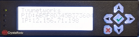
This is the perfect LCD for rack servers with quick integration and software available for Linux and Windows.
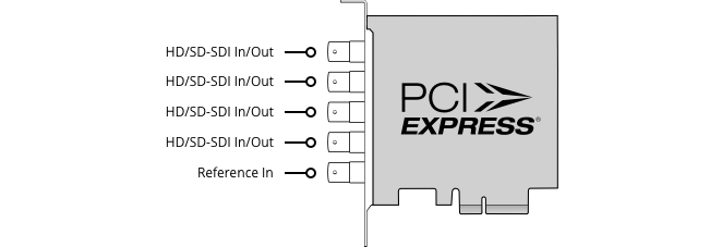
RPS 4-channel Duo 2 PCI Express card
The Duo 2 PCI Express capture and playback card features four independent 3G-SDI connections. The card supports SDI formats in SD and HD up to 1080p60 with the flexibility of 4 separate capture or playback cards in one.
Connections:
- SDI Video Inputs – 4 x bidirectional 12-bit SD/HD independently configurable as either Input or Output.
- SDI Video Outputs – 4 x bidirectional 12-bit SD/HD independently configurable as either Input or Output.
- SDI Audio Inputs – 16 channels embedded in SD and HD.
- SDI Audio Outputs – 16 channels embedded in SD and HD.
- Sync Input – Tri-Level or Black Burst.
- Server Interface – PCI Express 4 lane generation 2, compatible with 4, 8, and 16 lane PCI Express slots.
RPS 4-channel PCI Express card
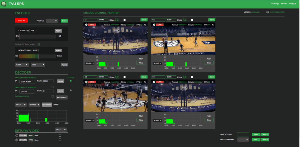
RPS 4-channel Web interface overview
The RPS v6.3 and higher 4-channel configuration uses the same TVU VS3500 server with the Duo 2 card in place of the standard Quad 2 card. The hardware is the same as our standard TVU RPS Transceiver, which comes with the Duo 2 card as described in “Rear panel overview” on page 3.
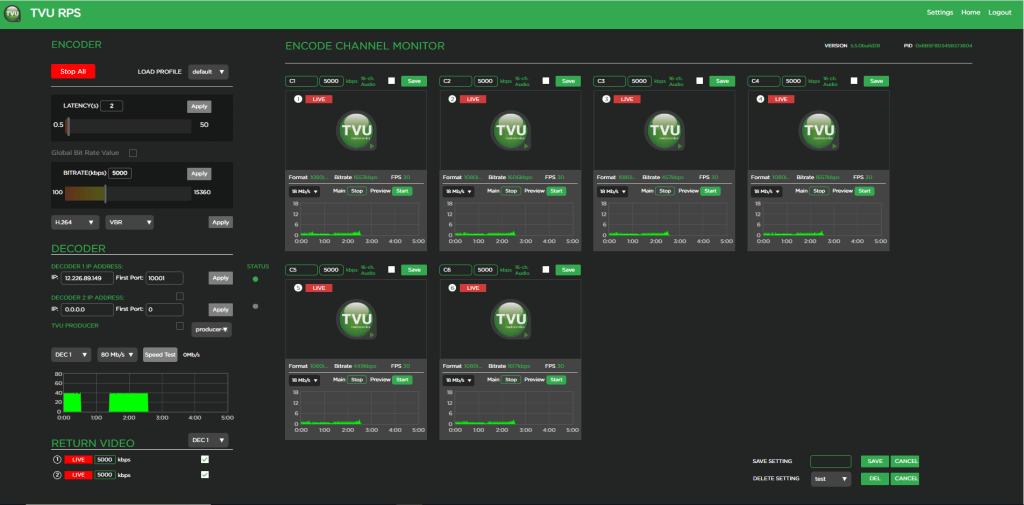
When a Duo 2 card is detected on the system, the main Web interface shows four previews instead of the standard six previews. The previews for the 4-channel configuration are much larger than the standard 6-channel version as shown in the following figures.
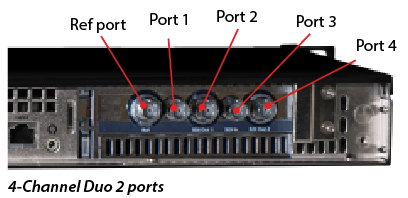
Port mapping 4-channel Duo 2 card
The port mapping for the RPS v6.3 and higher 4-channel configuration is from left to right. The leftmost port is the reference port, and to its right are port 1, port 2, port 3, and port 4. The reference port is used for genlock. Port 1 is for primary channel 1, port 2 is for primary channel 2, port 3 is for primary channel 3 or return video feed 1, and port 4 is for primary channel 4 or return video feed 2.
Port 3 and port 4 can either be used as the primary channel or return feed. You cannot use the primary and return feed at the same time as there is no separate dedicated port for return feed as with the 6-channel version for the Quad 2 card (where port 7 and 8 are for the return feed).
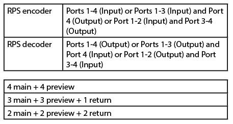
Encoder and decoder SDI port configuration table
Port configuration options
For information about port configurations, contact support@tvunetworks.com or refer to the TVU Server Port-forwarding guidelines.
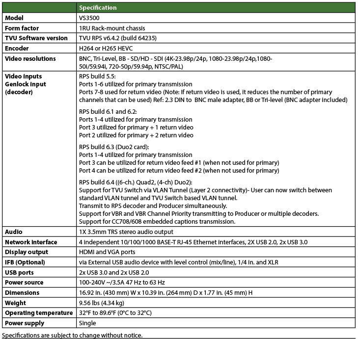
Chapter 2 – Product specifications
Chapter 3 – Applications overview
TVU RPS provides production solutions and applications
- TVU RPS supports 1080p/1080i/720p HD and NTSC and PAL formats.
- The system uses TVU’s Inverse Statmux Plus (IS+) transmission algorithm for stable, high-quality, low-latency transmissions. The system’s simple web interface gives real-time previews of all six channels and allows users to monitor and control all aspects of the transmission, including current bitrate and latency.
- TVU RPS provides multi-camera remote production for live coverage without the costs associated with expensive dedicated fiber or satellite links, extensive dedicated transmission equipment, and large on-site production crews.
- TVU RPS features a VLAN tunnel to allow IP devices in the field to virtually connect to the LAN in the studio, making it ideal for teleprompters, tally, remote cameras, and more.
- TVU’s VoIP solution, TVU Voice, is also compatible with TVU RPS, making communication between the field and headquarters easier than ever.
Applications
- 6-Channel Remote Multi-cam or Remote Studio Application
- 4-Channel Remote Multi-cam or Remote Studio Application with – Channel Return Video
- Remote Production System VLAN Tunnel Application – IP Intercom
- Remote Production System VLAN Tunnel Application – IP Tally
- Remote Production System VLAN Tunnel Application – CCU
© Copyright 2024 TVU Networks Corporation. All rights reserved in all media.
Document Part Number: TVU RPSVS3500 Hardware Setup Guide Rev F EN 03-2024