Contents
- Setup, configuration, and Going live
- Single and multi-camera connections
- Live status screen functions
- Going live
- Controlling multiple channels
- RPS One config tab
- Source Switch tab
- Stream tab
- Self-check tab
- Progressive download tab
- Standby and record modes
- Return Video tab
- Upload tab
- Transfer tab
- RPS One Advanced configuration – pack controls
- Connecting to the RPS One hotspot
TVU RPS One Model TM1100 Software QSUG v8.2
Before you begin
Before you use your TVU RPS One encoder, refer to the latest TVU RPS One Model TM1100 Hardware Quick Start User Guide to set up the hardware and identify the devices you intend to use with the unit, including cameras, cables, power sources, modems, TVU services, and unit accessories.
The TVU RPS One encoder running The One/RPS One Software version 8.2 (Build 82085) or later uses the same hardware, which features two LCD console interfaces:
- The One single-channel transmitter
- TVU RPS One multi-channel encoder
Note: To switch from a One to an RPS One console, contact TVU Support at support@tvunetworks.com. Once authorized, switching consoles is performed automatically. A reboot is necessary.
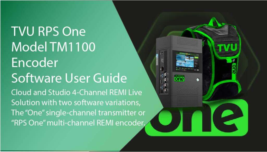
Single and multi-camera connections
The encoder’s LCD screen can be operated using single or multi-channel inputs. For input connection configurations and “Multi-Channel connections and behaviors,” refer to the following figures.
The following camera combinations are supported:
HDMI only – Up to 4K p60
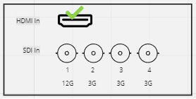
12G SDI In (1) only – Up to 4K p60
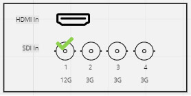
Up to 4 3G SDI In – Up to 1080 p60
About this guide
This software quick start user guide provides information about performing the basic configuration and operating the TVU RPS One encoder.
- Refer to the TVU RPS One Model TM1100 Hardware Quick Start User Guide to set up your hardware.
Turning on the RPS One
- Press the power button, and the RPS One transmitter will begin to boot up.
- The initial status screen will display.
- The modems begin to connect automatically.
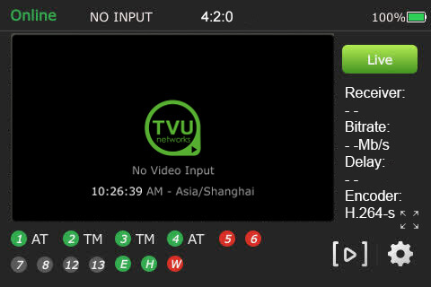
When no transmission feed is connected to the unit, “No video input” will display on the LCD touchscreen.
Note: you may be prompted to upgrade your firmware. If you choose to upgrade, click the notification at the top of the status screen. It may take up to 30 minutes to complete.
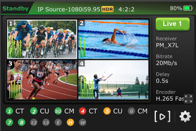
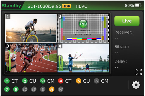
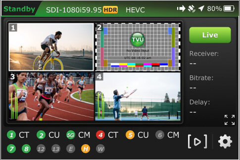
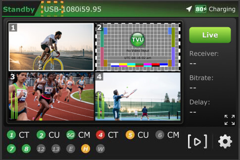
TVU RPS One encoder Live status screen functions
When SDI is connected, transmission control in the field is allowed.
(A) Transmission Status: The LCD touchscreen displays the RPS One’s current transmission status. When video input sources (SDI 1-4) are connected to the RPS One encoder, the touchscreen will display Standby until a channel is selected and taken “Live.”
(B) Data Card Status Monitor:
The status monitor displays the current number and status of all data cards connected to the RPS One. The status of data cards connected to the encoder will appear as green, red, orange, or black. Green status indicates that the data card is connected. Orange status indicates that the data card is attempting to dial. Red status indicates that the data card is not connected. Black status indicates that no card is present.
(C) Ethernet Connection: Displays the status of the Ethernet connection.
(D) Hotspot Connection: Displays the status of the hotspot connection.
(E) WiFi Connection: Displays the status of the WiFi connection.
(F) Latency Status: Displays the current latency of the transmission.
(G) Bit Rate Status: Displays the current Bit Rate (B/R).
(H) Receiver Name: Shows the receiver name to which the unit is transmitting.
(I) Audio Input Level Monitor: This monitor dynamically displays the unit’s audio input level (DBFS) with graphical colors.
(J) Battery Status: Indicates the status of the battery.
Going Live
To go live using the receiver with which you last went live:
- Tap the Live button on the initial status screen to start the live transmission.
- The RPS One unit will prompt you to slide the ‘Slide to go live’ button from left to right.
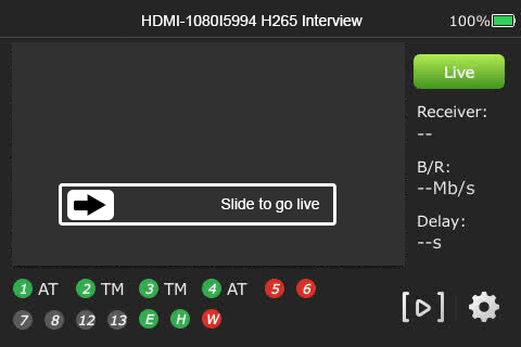
- Once the button is engaged, the RPS One begins the live transmission using the last receiver with which you most recently went Live.
Selecting a receiver and going Live
To select a receiver, configure your settings, and go Live, complete the following steps:
- Tap the center of the LCD touchscreen. The initial status screen displays. Tap the Settings gear icon on the bottom right of the LCD touchscreen.
- Tap the Config tab and then Receiver.
Note: To return to the previous screen, tap the Home button.
- Select the receiver with which you want to go live from the drop-down menu and tap the Go Live button.
- If you only want to select a receiver but do not want to go Live, tap the Back button at the bottom-right corner of the LCD touchscreen.
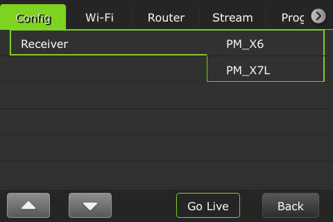
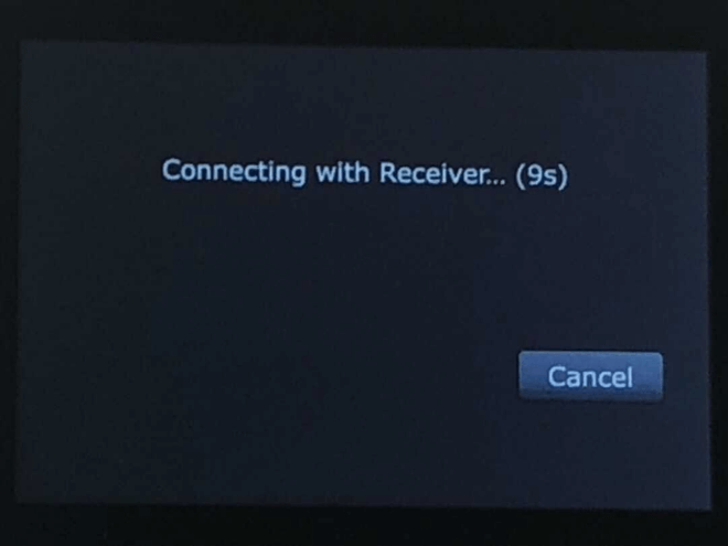
Note: When starting a live transmission from this menu, you will not be prompted to slide a button. The transmission will begin with a countdown.
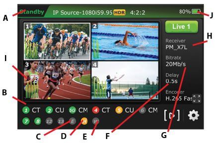
Controlling multiple channels
- Tap a channel and the green Live button.
- When a channel is live with a receiver, “PGM” displays next to the channel number on the top left of the preview screen.
- Press and hold the channel number preview to stop a Live transmission until the red Stop button displays.

- When the live transmission is stopped, the LCD displays “Standby” at the top left corner of the screen.
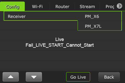
- The following message will be displayed if a live transmission fails after reboot.
Multi-channel operational modes
This section explains the RPS One operational modes and the expected behavior for each mode.
Users can select a multi-channel (group control) or single-channel (single mode) transmission on the touchscreen.
The RPS One displays the four connected SDI video input previews on the LCD touchscreen. It has two operational modes: single and group control. The RPS One default is group-control mode.
Multi-channel preview 1- 4 behavior
The video preview number displayed in the top-left corner of each video preview corresponds to the SDI video input channel.
- The Live source displays a red “PGM” next to the channel number on the top left of the video preview screen.
- When the source is in Preview mode, the video preview screen displays a green “PVW” next to the slot number at the top left.
- Only the channel number will be displayed when a source is not in PVW or PGM mode.
- Tap a video preview to enter the group-control mode (default).
- Tap and hold a video preview for 3 seconds to control the channel independently. To control another channel and return to group-control mode, wait 20 seconds between selections, then press another preview.
- Tap the video preview, then the full-screen icon to enable the full-screen preview.
- Tap a PGM or PVW video preview, then the “>” in the right panel to display the Tally banner.
Starting and stopping a multi-channel transmission
- The Live All button will display on the LCD touchscreen when all channels are detected.
- Tap a live preview and the Stop All button on the LCD touchscreen to stop all live multi-channel transmissions.
Starting and stopping a single-channel transmission
To start a single-channel transmission:
- Tap a video preview and press for two seconds.
- Tap the Live button. You will notice that the selected channel number will be displayed on the “Live” button.
- When the channel is transmitting, the preview window will be framed in red, and “PGM” will display in red next to the channel number.
- To take another preview live, wait 20 seconds and repeat the process.
To stop a single-channel live transmission:
- Tap, press, and hold the channel number preview.
- Tap the red Stop button.
Full-screen preview
To enable single full-screen views from the touchscreen.
- Select a channel and tap the full-screen icon.
- To return to the multi-view display, tap the bottom-right icon.
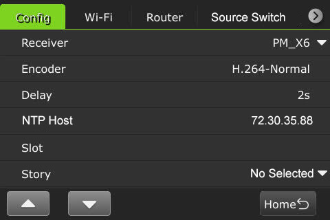
RPS One configuration settings
Users can open the Settings page by tapping the Gear icon on the initial status page to display the Config tab. This section describes the list of settings and how to configure them.
Selecting an encoder option
The TVU RPS One has true dual encoding. It encodes the same content at a fixed bitrate in the background and records to local storage. Users can monitor the live-stream bitrate. A visual notification is displayed on the home screen if the selected transmission bitrate drops below the threshold.
The TVU RPS One model TM1100 supports onboard H.265/HEVC or H.264 encoding.
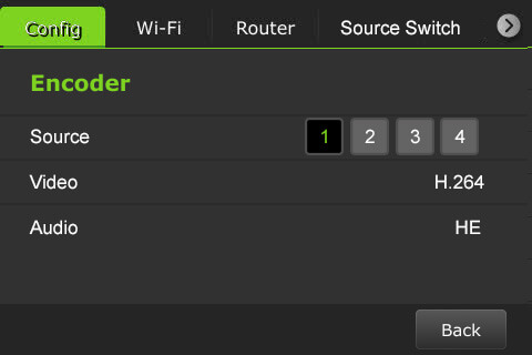
To select an encoding option:
- Tap the Settings gear icon to open the Settings screen, then tap Encoder.
- Select an input Source channel.

- Tap Video to open the Video Encode menu.
- Configure the Encoding and HDR/HLG settings.
HDR / HLG Explained
HDR (High Dynamic Range) increases contrast and color range, displaying brighter highlights and deeper shadows for more realistic images.
HLG (Hybrid Log-Gamma) is a type of HDR designed for broadcast; compatible with both HDR and standard displays without needing metadata, making it ideal for live production.
Using 8-bit with HDR/HLG often results in visible artifacts, especially in smooth gradients. For effective HDR, 10-bit or higher is strongly preferred.
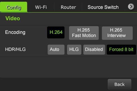
Note: Your selection will highlight green. The RPS One must be in live mode before you can change selections.
Chroma Subsampling: 4:2:0 vs 4:2:2
Chroma subsampling reduces color information to save bandwidth while preserving image detail.
- 4:2:0 samples color at half the horizontal and vertical resolution; best for streaming or storage-efficient video with lower color fidelity.
- 4:2:2 samples color at full vertical resolution and half horizontal; preserves more color detail, preferred for professional editing or broadcast.
- H.265 Interview
- H.264 Normal
- H.265 Fast Motion
- Tap the Back button.
- Tap Audio to open the Audio Encode menu.
- Tap Audio to select a Profile, Mode, Channel, and Bitrate settings.
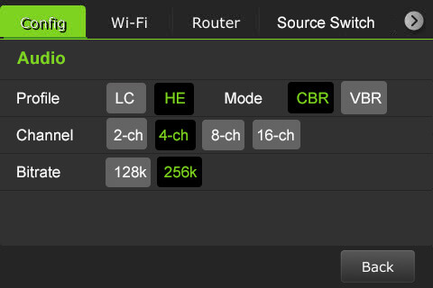
- To return to the Encoder menu, tap the Back button.
- To return to the Settings menu, tap the Back button.
Delay management
To manage the second and sub-second Latency settings:
- Tap the Settings gear icon to open the Settings screen.
- Tap the Config tab, then Delay to configure the latency.
- Tap a box and use the up and down buttons to set the delay.
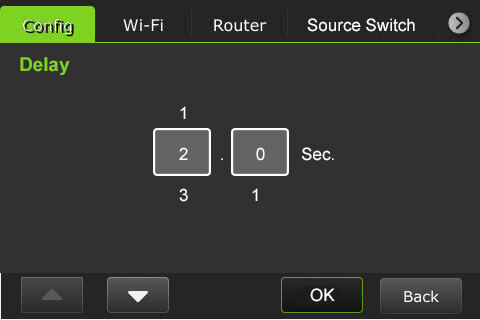
- Tap OK to confirm your settings. Tap the Back button to return to the Config settings menu.
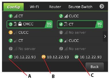
Data card monitoring
To monitor detailed encoder information along with Ethernet, hotspot, and WiFi connections:
- Tap the bottom of the main screen.
- The data cards and their status display along with Ethernet, Hotspot, and WiFi indicators:
(A) Ethernet
(B) Hotspot
(C) WiFi connection
Slot speed
A user can view the speed of each slot in real-time. To view a slot speed:
- Tap the “>” to view the real-time speed of a slot. The selected slot is framed in green.
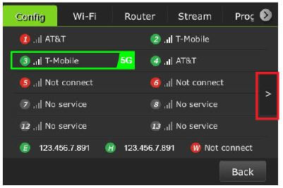
- The slots’ real-time speed is displayed.

- To return to the slot screen, tap the “<” icon.
- To return to the Settings menu, click the Back button.
RPS One encoder information
To access the RPS One model number, Peer ID, software version, App version, and region:
- Tap the Settings gear icon to display the Config tab.
- Scroll down and tap About.
- The encoder’s information window displays.
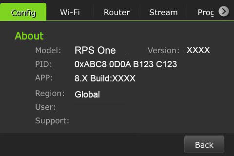
- To return to the Settings menu, tap the Back button.
Language selection
The Config tab allows the user to choose English and Chinese languages.
To select a language:
- Tap the Settings gear icon to display the Config tab.
- Scroll down to tap the Language option. The default is English.
- Select your location option using the up and down arrows.
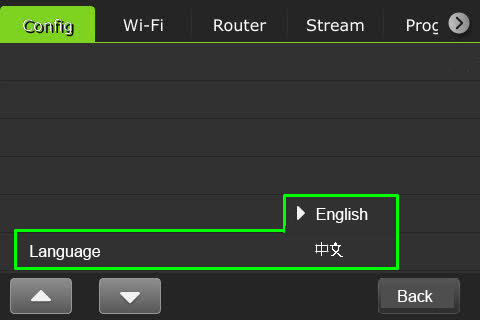
- When finished, tap the Back button.
Source Switch tab
By selecting the Source Switch tab, a user can enable the Source Switcher mode to switch between sources 1, 2, 3, and 4 from the touchscreen and output to a single receiver. Alternatively, users can control SDI Source Switching using a Keyboard or Web UI, which is further explained in the “RPS One Software Advanced Configuration Guide.“
To enable the Source Switcher on the touchscreen:
- Tap the gear icon to open the Settings screen.
- Tap the Source Switch tab. Move the Source Switcher toggle to the right until it turns green.
- Move the Add to Home Screen toggle to the right until it turns green to add the switch to the Home screen.
- Select one receiver from the Receiver drop-down menu. The default receiver is the one you are currently live with.
Note: it is not possible to output each source to unique receivers in this mode.
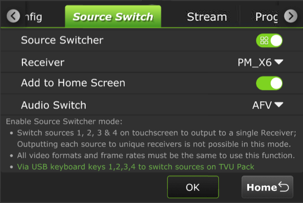
- Select an audio switch setting from the AFV menu.
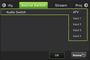
- This option determines the audio source for the SDI Source Switcher. Your menu selections are:
- Default – AFV: Audio follows a video where the audio switches along with the video.
- Input 1: The audio always comes from Input 1, regardless of the selected SDI source.
- Input 2: The audio always comes from Input 2, regardless of the selected SDI source.
- Input 3: The audio always comes from Input 3, regardless of the selected SDI source.
- Input 4: The audio always comes from Input 4, regardless of the selected SDI source.
Note: When the device is live, the receiver settings cannot be modified and the audio cannot be locked to the source that has no video input.
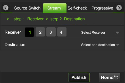
Stream tab
Using the Stream tab, a user can remotely control the stream output destination of a receiver.
- Tap the Stream tab.
- Select a channel and receiver from the Receiver list drop-down list. Then, select a destination from the Destination drop-down list and tap Publish.
- To stop the stream, tap Stop.
Note: When the Stream is Live the destination selected displays red, when loading the status is yellow. Receivers that are available display white.
Self check
The Self Check panel lets you self-check your devices’ basic, video, battery, and network health status. This feature is further explained in the “RPS One Software Advanced Configuration Guide.”
To perform a self-check on your device from the LCD screen:
- Tap the Self-check tab.
- Tap one or all Basic, Video, and Network checkboxes.
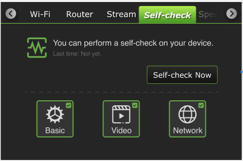
- Tap the Self-check Now button to run diagnostics on your device.
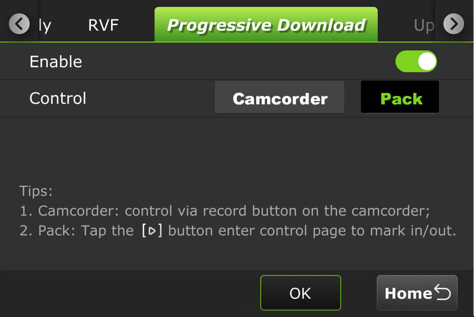
Progressive Download tab
Enabling the Progressive download feature allows users to record clips by connecting a camcorder to the SDI input. The camcorder record button controls the recording. Clips are downloaded, transferred, and taken live using the Pack Control mode.
The ” RPS One Software Advanced Configuration Guide ” further explains operating the Progressive download feature in Camcorder or Pack mode, and the “File-based Workflow Reference Guide” further explains recording.
To use the Progressive Download feature:
- Select a channel and tap the gear icon to open the Settings screen.
- Tap the Progressive Download tab.
- Continue to “Camcorder mode” or “TVU Pack control mode.”
Camcorder mode
Camcorder mode can only be used with an SDI input. The time code must be inside the SDI signal.
- Tap the Camcorder button and enable the slider to the right until green.
- Tap OK.
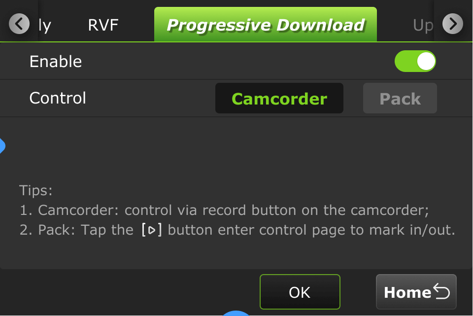
- Press the Record button on the video camera to display its controls.
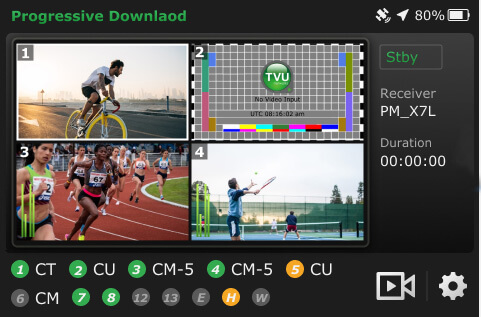
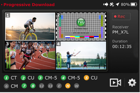
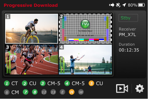
Standby and Record modes
- Standby “Stby” displays in green when in camcorder mode and not recording.
- When the video camera is recording, “•Rec” displays in red.
- Standby “Stby” displays in green when the video camera is finished recording.
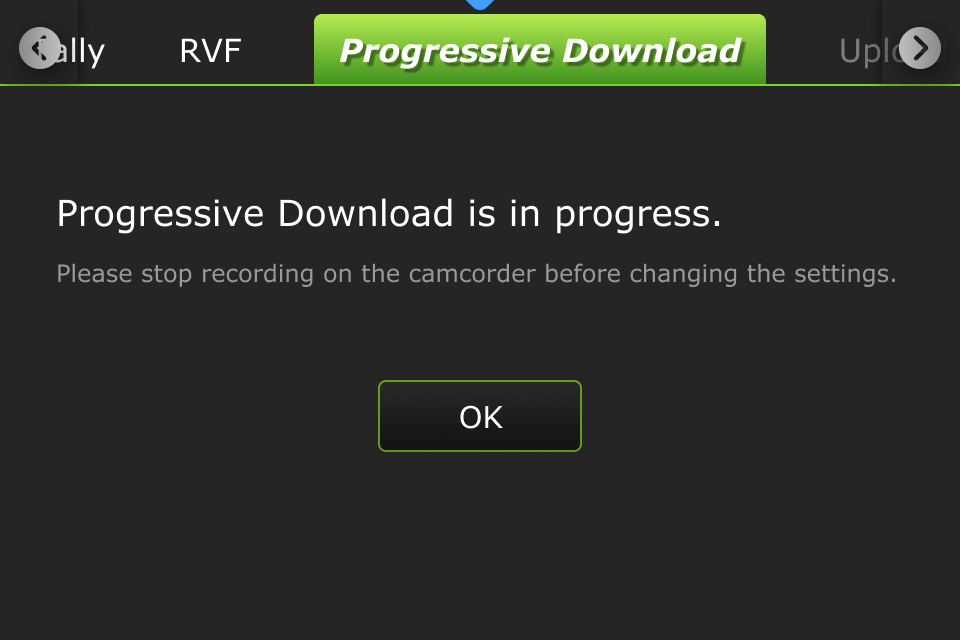
Note: Stop the video camera from recording if you need to change your pack settings.
If you change the settings to the Pack while Camcorder mode is running, the following message will appear:
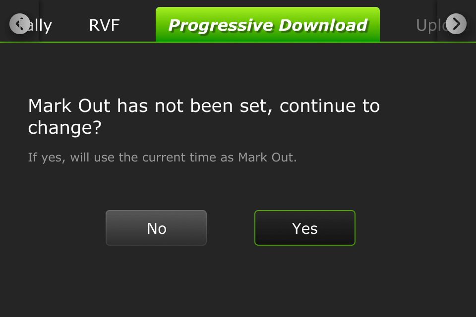
If you change to Camcorder mode when running in Pack mode and the Mark In point is set but the Mark Out point is not, the following message displays. The processing becomes interrupted and defaults to the current Mark Out point.
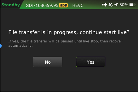
A new file transfer ![]() icon displays in the top status bar when a file transfer is in progress. If you take the clip live during the transfer process, the following message will display:
icon displays in the top status bar when a file transfer is in progress. If you take the clip live during the transfer process, the following message will display:
TVU Pack control mode
Pack control mode can be used in either SDI or HDMI. A time code is not required. Clips are downloaded, transferred, and taken live using the Pack Control mode.
To enable the Progressive Download Pack mode:
- Select a channel and tap the Settings gear icon.
- Tap the Progressive Download tab.
- Tap Pack and move the enable slider to the right until green.
- Tap OK. A Success prompt is displayed.
- Tap the Home button. Your feed will display in “Standby” mode.
- Tap the
 icon to enter the control page to set your mark-in/out preferences.
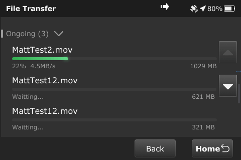
When a file is being transferred using the Progressive Download, download, and Auto Sync, methods a new file transfer ![]() icon displays in the top status bar of the LCD touchscreen. A prompt will display if a file is being transferred when the Pack is shutting down.
icon displays in the top status bar of the LCD touchscreen. A prompt will display if a file is being transferred when the Pack is shutting down.
The transfer ![]() icon displays when a file is being transferred. Tap the Transfer tab to view the file transfer details.
icon displays when a file is being transferred. Tap the Transfer tab to view the file transfer details.
- The
 icon is red when a Progressive Download is in progress.
 - The camera
 icon is red when the RPS One is live with a receiver.
The “RPS One Software Advanced Configuration Guide” further explains how to transfer, mark, and take a clip live.
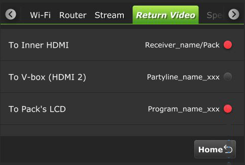
Return Video tab
Version 8.2 supports separate return video feedback (RVF) with the Pack and an RPS receiver.
The Return Video tab has three modes, allowing users to set up RVF from a Receiver, Producer, or Partyline session. These modes can be output to:
- Inner HDMI
- V-box 2 (HDMI 2)
- The Pack’s LCD
Note: When enabled, a single return video can be simultaneously output to multiple outputs, such as two HDMI ports, the Pack’s LCD screen, and a phone or tablet.
The return video feed type setting is accessed from the Settings gear icon > Return Video tab.
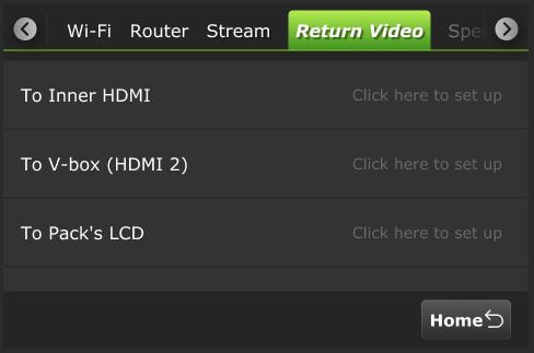
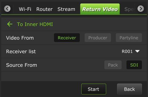
To Inner HDMI
To set up RVF from a Receiver To Inner HDMI:
- Tap the Return Video tab.
- In the To Inner HDMI panel, tap Click here to set up.
- The To Inner HDMI screen will display.
- In the Video From panel, tap Receiver.
- Select a Receiver from the Receiver list drop-down menu.
- In the Source From panel, select Pack or SDI.
- Tap Start.
- Tap the Back button to return to the previous screen.
- Tap the circle to select your output(s). Selections will turn red.
- Then, tap the Home button.
To set up RVF from a Producer session To Inner HDMI:
- Tap the Return Video tab.
- In the To Inner HDMI panel, tap Click here to set up.
- The To Inner HDMI screen will display.
- In the Video From panel, tap Producer.
- Select a Program from the Select Program drop-down menu.
- Tap Start.
- Tap the Home button to return to the previous screen.
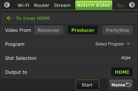
- Tap the circle to select your output(s). Selections will turn red.
- Then, tap the Home button.
To set up RVF from a Partyline session To Inner HDMI:
- Tap the Return Video tab.
- In the To Inner HDMI panel, tap Click here to set up.
- The To Inner HDMI screen will display.
- In the Video From panel, tap Partyline.
- Select a Partyline Source.
- Tap Start.
- Tap the Home button to return to the previous screen.
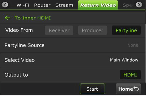
- Tap the circle to select your output(s). Selections will turn red.
- Then, tap the Home button.
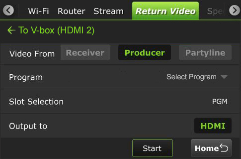
To set up RVF from a Receiver To V-box (HDMI 2):
- Tap the Return Video tab.
- In the To V-box (HDMI 2) panel, tap Click here to set up.
- The To V-box (HDMI 2) screen will display.
- In the Video From panel, tap Receiver.
- Select a receiver from the Receiver list drop-down menu.
- In the RVF type panel, select Pack or SDI.
- Tap Start.
- Tap the Back button to return to the previous screen.
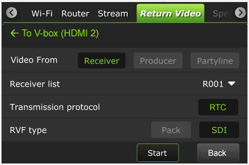
- Tap the circle to select your output(s). Selections will turn red.
- Tap the Home button.
To set up RVF from a Producer session To V-box (HDMI 2):
- Tap the Return Video tab.
- In the To V-box (HDMI 2) panel, tap Click here to set up.
- The To V-box (HDMI 2) screen will display.
- In the Video From panel, tap Producer.
- Select a Program from the Select Program drop-down menu.
- Tap Start.
- Tap the Home button to return to the previous screen.
- Tap the circle to select your output(s). Selections will turn red.
- Tap the Home button.
To set up RVF from a Partyline session To V-box (HDMI 2):
- Tap the Return Video tab.
- In the To V-box (HDMI 2) panel, tap Click here to set up.
- The To V-box (HDMI 2) screen will display.
- In the Video From panel, tap Partyline.
- Select a Partyline Source.
- Tap Start.
- Tap the Home button to return to the previous screen.

- Tap the circle to select your output(s). Selections will turn red.
- Tap the Home button.
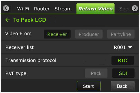
To Pack’s LCD
The VFB connects from the transmitter’s HDMI Out port. When the VFB function is enabled on an RPS TVU One, the VFB allows the return video feed to be transferred from a receiver in the field and displayed on the Pack LCD in real time.
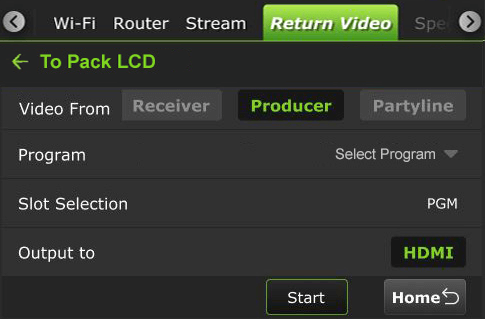
To set up the Return Video Feedback from the RPS One:
- Tap the Return Video tab.
- In the To Pack LCD panel, tap Click here to set up.
- The To Pack LCD screen will display.
- In the Video From panel, tap Receiver.
- Select a receiver from the Receiver list drop-down menu.
- In the RVF type panel, select Pack or SDI.
- Tap Start.
- The preview will be displayed on the Pack’s LCD screen.
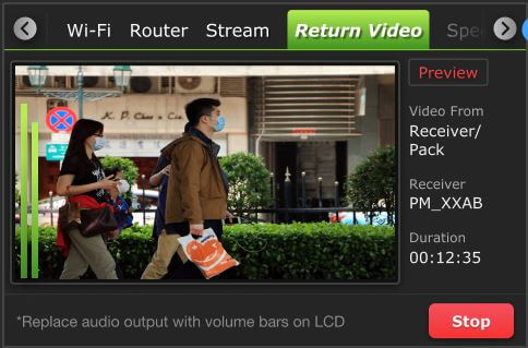
- To stop the output, tap the Stop button.
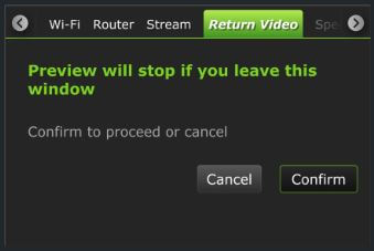
- If you navigate to another screen, the following message will be displayed. You can choose to Cancel or Confirm the operation.
To set up RVF from a Producer session To Pack LCD:
- Tap the Return Video tab.
- In the To Pack LCD panel, tap Click here to set up.
- The To Pack LCD screen will display.
- In the Video From panel, tap Producer.
- Select a Program from the Select Program drop-down menu.
- Tap Start.
- The preview will be displayed on the Pack’s LCD screen.
- To stop the output, tap the Stop button.
- If you navigate to another screen, the following message will be displayed. You can choose to Cancel or Confirm the operation.
To set up RVF from a Partyline session To Pack LCD:
- Tap the Return Video tab.
- In the To Pack LCD panel, tap Click here to set up.
- The To Pack LCD screen will display.
- In the Video From panel, tap Partyline.
- Select a Partyline Source.
- Tap Start.
- Tap the Home button to return to the previous screen.

- The preview will be displayed on the Pack’s LCD screen.
- To stop the output, tap the Stop button.
- If you navigate to another screen, the following message will be displayed. You can choose to Cancel or Confirm the operation.
Upload tab
Using the Upload tab, users can upload files from a USB flash drive to a Receiver:
- Tap the Upload tab.
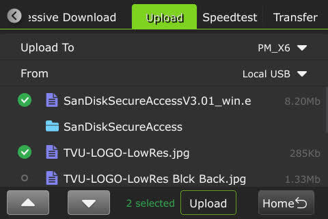
- Select a receiver from the Upload to drop-down list, then select a USB source in the From drop-down list.
Transfer tab
To view file transfer status, including progressive download, download, and auto-sync:
- Tap the Transfer tab.
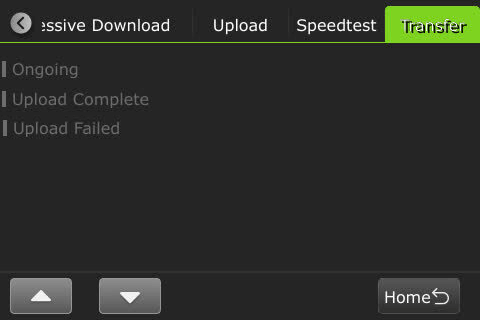
- The following status displays when the file transfer is ongoing.
- The following status displays when the file transfer is complete.
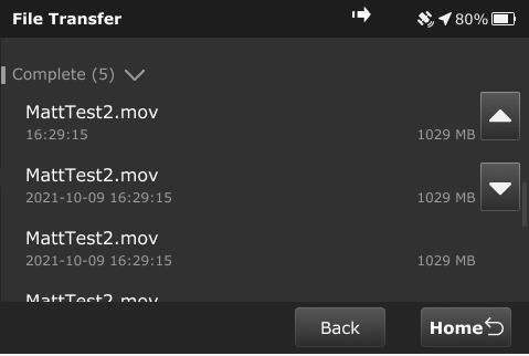
The following message displays if file transfers are in progress when powering off the device.

RPS One system status monitoring and control using a Web browser, iPhone, or smart mobile device
The RPS One encoder’s operational status can be monitored, and various transmission functions can be controlled from a Web browser. This interface can be accessed using a standard web browser connected to the RPS One hotspot.
Connecting to the RPS One hotspot
Complete the steps to connect a laptop or phone to the internal hotspot.
- Search for the hotspot on your iPhone/smart device. Then, when prompted, enter the case-sensitive SSID:
TVUPACK_XXXX
(Where X is the last 4 digits of the encoder’s PID)
The default password is the last 8 digits of the RPS One PID.
Note: All password characters are uppercase. The password can be changed in the Web UI if desired.
- Connect to the SSID using your iPhone or smart device. The following examples show how the status screens display on a smart device’s Web browser.
- Once the connection is established, you can open a web browser and enter http://192.168.4.1 in the address line to see the RPS One’s “System status.”
- The TVU RPS System status panel displays.
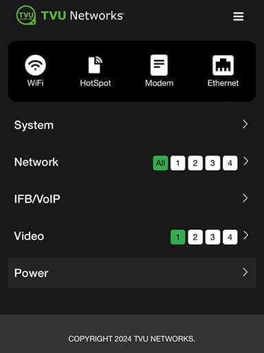
The System status screen provides detailed information on the System, Network, IFB/VoIP, and Video status.
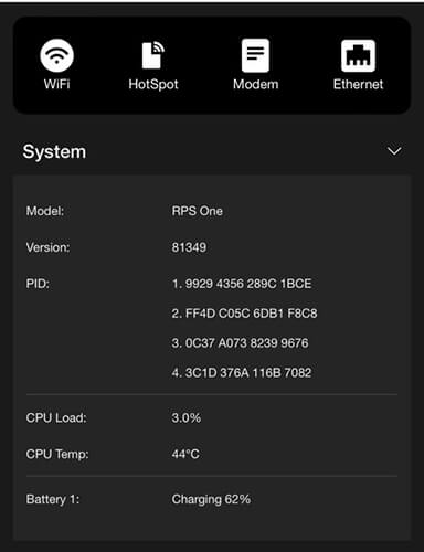
System panel
Expand the System caret to display System status, model, software version, and PID information.
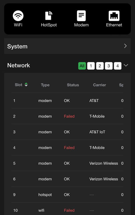
Network panel
The Network panel displays the current Network status.
IFB/VoIP panel
The IFB/VoIP panel allows the user to change the audio level of the IFB function. The audio-only option is only available if the licensed feature is enabled.
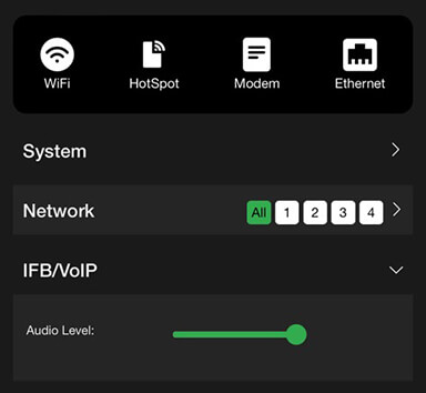
Video panel
The video panel displays information on video transmission and its status.
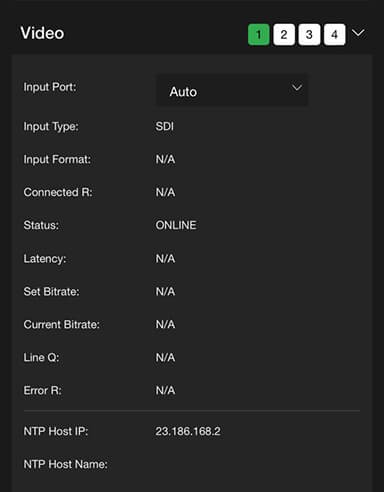
The Video panel allows users to select USB as the Input Port when the pack detects a USB video input source.
Supported USB cameras are:
- DJI Osmo Pocket 3 Pro
- DJI Osmo Action 5 Pro
- Logitech Brio 100
- Hikvision DS-U11
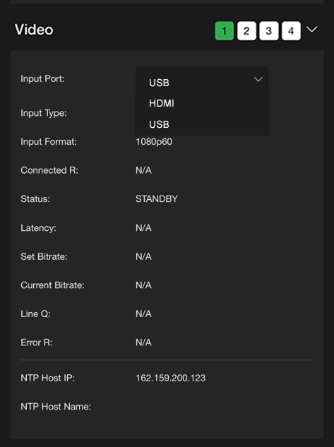
When selecting USB as a video input port, set 1080P30 as the Input format.
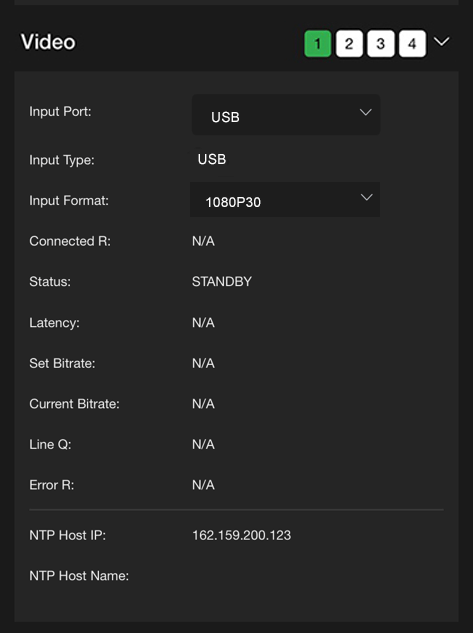
When the USB setting is successful, the USB input will be displayed at the top of the pack’s Home LCD touchscreen.
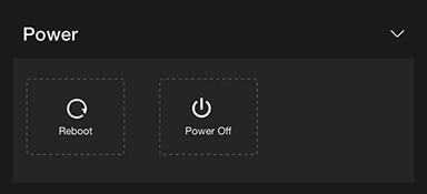
Power panel
The Power panel allows users to reboot and power off the pack.
Network configuration
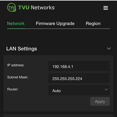
To open the Network configuration panel:
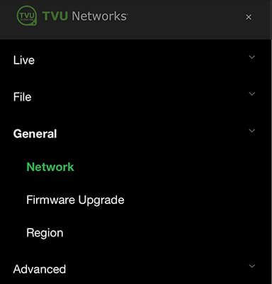
- Tap the three-bar icon to open the advanced operations panel.
- Tap the General drop-down menu and select Network. This allows users to navigate to, monitor, and control all aspects of transmission.
- In the LAN settings panel, set the RPS One’s local LAN address. The default IP address is 192.168.4.1.
- Enter the Subnet Mask and select a Router setting from the drop-down menu; the default is Auto.
- Click Apply.
- Use the following procedures to scroll through the remaining Network options to complete the configuration settings:
- Hotspot
- WiFi
- Ethernet
- Modems
WiFi configuration and settings
The WiFi menu provides configuration information and access to change the WiFi settings. The RPS One can optionally support multiple WiFi connections by purchasing optional hardware. For more information, contact TVU Networks support.
When multiple WiFi adapters are connected, you can scan available slots for WiFi adapters and configure the WiFi login information using the RPS One WiFi setup and configuration panel.
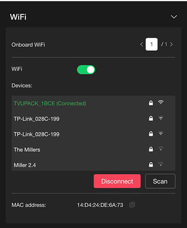
Configuring WiFi
Complete the steps in the following procedure to configure your WiFi settings:
- Tap the WiFi icon.
- Press the Scan button to display any available networks. The available networks are displayed in the center panel. Choose the desired network from the center panel.
- Move the WiFi slider to the right to enable it and connect it to the selected device.
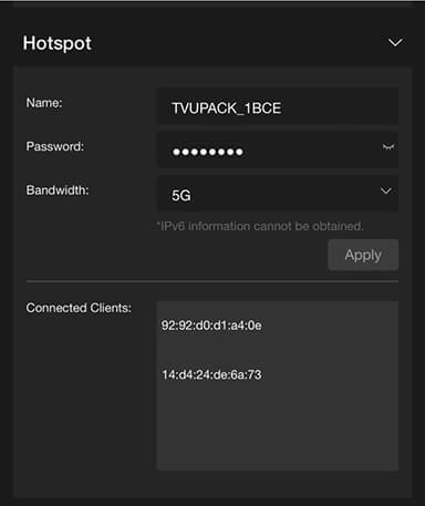
TVU RPS One hotspot settings
The hotspot panel provides status information about clients connected through the hotspot.
Configuring hotspot
Complete the following steps to configure a hotspot:
- Tap the Hotspot icon.
Note: The Connected Client list window displays a list of devices that are connected using hotspots.
- To update the Password, edit the password field.
Note: The new password must be 8 characters and does not take affect until the system is restarted.
- The hotspot feature enables a connected device to access the Internet through one of the available network connections. This access allows file transfers via FTP or any other internet connection. If higher bandwidth is required, refer to the topic “Router feature.”
- You can manually select the route taken (for example, a Hotel WiFi network) by selecting the path from the WiFi panel.
- In the Bandwidth drop-down menu, choose 2.4 GHz or 5 GHz frequency.
- Click Apply to save your changes.
Modem configuration
The Modem screen provides modem configuration information. The RPS encoder automatically detects many cellular data cards and will self-configure. If this is the case, no further action will be required. If a data card needs configuring, you can use the Modem panel to configure specific data cards.
- Tap the Modem icon.
- The Modems panel opens. Encryption is set to Auto by default.
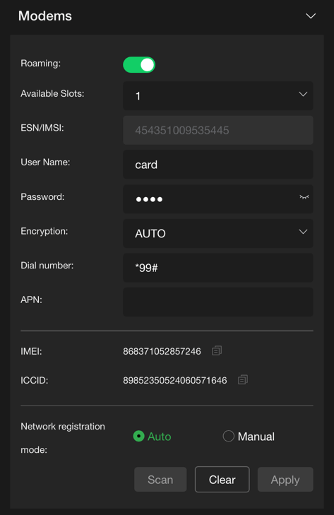
- Select the Manual radio button to configure specific data cards.
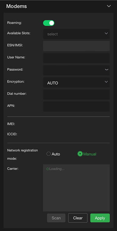
Configuring data cards
To configure specific data cards:
- Click the Available Slots drop-down menu to display a list of available slots for configuration.
- Under the Network registration mode, if Manual configuration is required, input the settings provided by your carrier.
- Click Apply to save any changes.
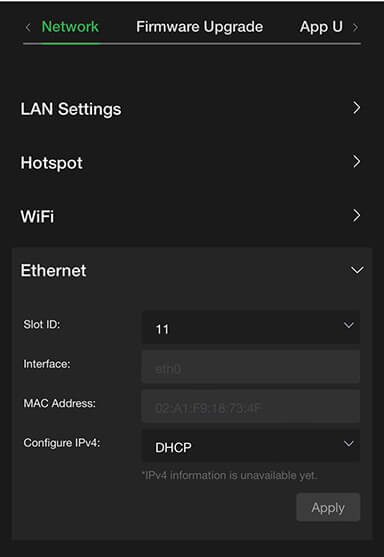
Ethernet configuration DHCP IP
Ethernet settings are accessed and configured from the System configuration Home panel.
Note: The DHCP IP address is automatically generated and cannot be manually entered.
To configure your Ethernet settings for a DHCP IP address:
- Open the Web browser UI and tap the Ethernet icon.
- Tap the Configure IPv4 drop-down menu and select DHCP.
- Tap the Slot ID drop-down menu and select a slot number.
- Tap Apply.
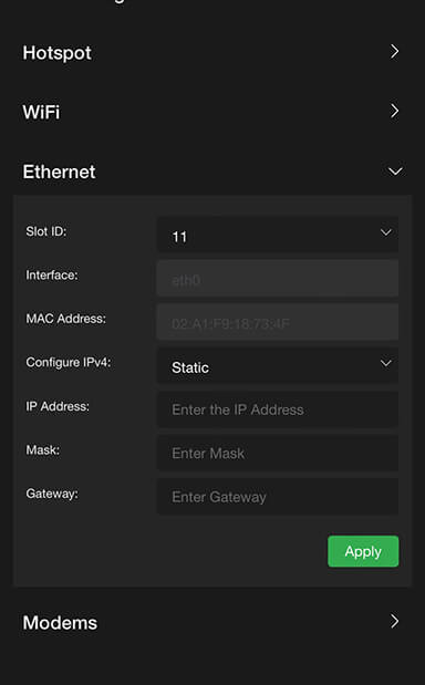
Ethernet configuration Static IP
To configure your Ethernet settings for a Static IP address:
- Tap the Configure IPv4 drop-down menu and select Static IP.
- Tap the Slot ID drop-down menu and select a slot number.
- Enter a Static IP address in the IP Address field.
- Enter the Subnet Mask in the Mask field.
- Enter the Gateway in the Gateway field.
- Tap the Apply button to save your changes.
Router feature
Note: This feature must be enabled by support before it can be used.
To use the Router feature:
- Tap the gear icon to open the Settings screen.

- Tap the Router tab. The router setting is off by default. Tap and move the router slider to the right until it turns green.
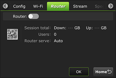
- When the router setting is in the on position, the following screen displays.
- To enable the Ethernet host setting, tap and move the Ethernet Host slider to the right until it turns green.
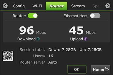
TVU Router feature (client connections)
If higher bandwidth is required when using a hotspot, the optional TVU Router feature can allow clients to connect to the RPS One at speeds of up to 200 Mbps.
- To access the Configuration page using an iPhone or smart device, open a web browser tab and enter http://192.168.4.1.
- Tap the Hotspot icon to open the advanced operations panel.
- Tap the Network tab and expand the LAN Settings panel.
- Select Auto in the Router drop-down menu.
- Enter the IP address and Subnet Mask, then click Apply.
- Scroll down on the Hotspot panel. Connected Clients display in the Connected Clients device list.
© Copyright 2025 TVU Networks Corporation. All rights reserved in all media.
Document Part Number: TVU RPS One Model TM1100 Software QGUG Rev F EN 10-2025