Contents
- Introduction, setup, and base operation
- Features overview
- About this guide
- Model TE5500 front and back panel overviews
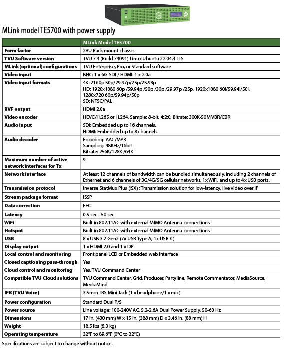
- Model TE5700 front and back panel overviews
- Before you begin
- Model TE5500 setup
- Model TE5700 setup
- MLink TE5700 front panel controls and operations
- Step 1 – Powering the TVU MLink TE5700 On and Off
- Step 2 – Choosing a transceiver
- Step 3 – Choosing a preset transmission mode
- Step 4 – Going live with your transmission
- Step 5 – Using the display or HDMI port
- Advanced Configuration
- Antenna configuration: RPS Link and MLink v7 model TE5700
- Advanced transmitter operations – Web interface controls
TVU MLink TE5500 and TE5700 User Guide v7.4
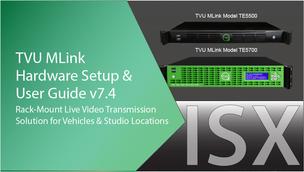
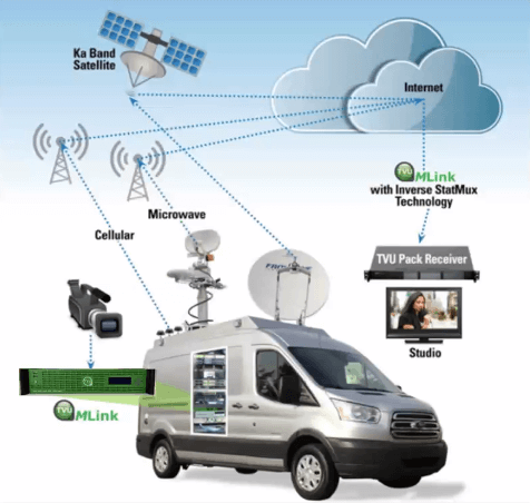
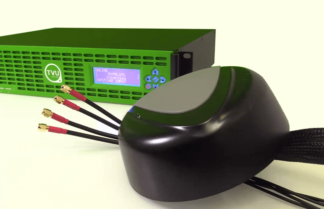
TVU MLink is the complete and versatile rack-mount IP video solution designed specifically for use in vans, trucks, sport utility vehicles, and in fixed studios. MLink uses all cellular 3G/4G/LTE/5G, satellite, microwave, WiFi, and Ethernet connections to transmit a high-quality and reliable video stream in HD with sub-second latency. A stream can be started with any type of connection, with additional ones added or removed at any time without video disruption.
Introduction, setup, and base operation
The TVU MLink features Inverse StatMux Plus (ISX) technology for dependable video broadcast in even the most challenging transmission environments, such as a moving vehicle. TVU MLink uses IP67-rated external roof-mounted antennas to ensure the best possible signal strength.
The TVU MLink transmitter also features the new TVU 7 platform, which supports the TVU Partyline feature.
TVU MLink overview
TVU MLink models TE5500 and TE5700 are a part of the TVU ecosystem. The video streams from MLink can also be easily distributed to multiple locations using TVU Grid® for live video switching, routing, and distribution solutions.
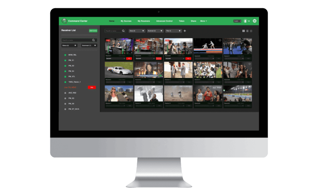
The TVU MLink TE5500 transmitter (encoder) uses the TVU Command Center Web interface, which provides a cloud-based centralized management and control solution for all TVU devices and services. For detailed information about TVU Command Center, refer to the “TVU Command Center Setup and User Guide.“
Features overview
TVU MLink Model TE5500 contribution encoder:
- MLink TE5500 is an ISX transmitter in a 1RU rack-mount form factor.
- Auto-senses and supports virtually all video formats 4K 25/30P, 1080p, 1080i, 720p, NTSC/PAL transmission using HEVC or H.264 VBR or CBR encoding (300K-50Mb/s).
- Connect to virtually any live professional/consumer video device via 6G-SDI or HDMI 2.0a input, including cameras, video routers, pool feeds, video switchers, video players, and more.
- Ultra-low latency transmission over commodity internet. Glass-to-glass latency as low as 500ms over cellular / 350ms over Ethernet.
- Supports up to 16 SDI-embedded audio channels or 8 channels of HDMI-embedded audio.
- Single Ethernet port for commodity internet connectivity.
- Support for TVU Return Video Feed via rear-panel HDMI port.
- Status monitor output via DP or HDMI.
- Talkback support uses TVU Voice (2-way voice) or traditional IFB (package dependent).
- Supported as a source when used with TVU Partyline for collaboration.
- Dual encoder support (package dependent); one is dedicated for live transmission, and the other automatically records in a 7.5 hour, 8 Mbps CBR loop anytime an input is connected (whether you are live or not). Access recordings locally or via the TVU Transceiver back at the studio.
- Upload files from the field using a connected USB device (thumb drive or HDD/SSD) with file management capability (Package dependent).
- Web-based ConfigT interface for local or remote monitoring and control. Supports up to 6 IP source inputs.
- Supports HTTP, UDP, RTMP, and RTMPS protocols.
- Directly compatible with TVU Cloud production tools, including TVU Command Center, TVU Producer, TVU Partyline, TVU Channel, and TVU CloudR.
TVU MLink Model TE5700 – ISX field / Remote uplink:
- The MLink TE5700 is an ISX transmitter in a 2RU rack-mount form factor.
- Aggregates any mix of cellular, Ethernet, WiFi, satellite, and microwave.
- Supports up to 6 embedded LTE or 5G modems. Ships standard with external IP67 rated external LTE antennas (3m cables) or optional 5G antennas.
- Has the ability to support a mix of 5G (optional) /LTE/4G and 3G modems (internal to the chassis) with external SMA antenna connections (4x SMA per 5G Modem, 2x SMA per LTE modem). The MLink TE5700 allows modem antennas to connect directly to the chassis, simplifying cabling.
- Auto-senses and supports virtually all video formats, including 4K (25/30P), 1080p, 1080i, 720p, NTSC/PAL transmission using HEVC or H.264 VBR or CBR encoding (300K-50Mb/s).
- Connect to virtually any live professional/consumer video device via 6G-SDI or HDMI 2.0a input, including cameras, video routers, pool feeds, video switchers, video players, and more.
- Super low-latency transmission over commodity internet. Glass-to-glass latency as low as 500ms over cellular / 350ms over Ethernet.
- Supports up to 16 channels of SDI-embedded audio or 8 channels of HDMI-embedded audio.
- Dual encoder support (package dependent); one is dedicated for live transmission, and the other automatically records in a 7.5 hour, 8Mb/s CBR loop anytime an input is connected (whether you are live or not). Access recordings locally or via the TVU Transceiver back at the studio.
- File upload management; Upload files from the field using a connected USB device (thumb drive or HDD/SSD) with file management capability (package dependent).
- Web-based ConfigT interface for local or remote monitoring and control. Supports up to 6 IP source inputs.
- Easily accessible front panel SIM card slots for easy configuration.
- Front panel LCD interface for easy configuration, control, and monitoring.
- Embedded outbound WiFi module with external antenna support (MIMO) for use with ISX transmissions.
- Embedded HotSpot WiFi module with external antenna support (MIMO) for access point use (Internet connectivity).
- Support for TVU Return Video Feed via rear-panel HDMI port.
- Talkback support uses TVU Voice (2-way voice) or traditional IFB (package dependent).
- Supported as a source when used with TVU Partyline for collaboration.
- Optional TVU Router support (TVU model RE980 only) which turns MLink into a high-speed access point in virtually any location. All data connections are aggregated together to provide high-speed connectivity.
- Optional dual power supply
- Directly compatible with the TVU Cloud production tools, including TVU Command Center, TVU Producer, TVU Partyline, TVU CloudR, and TVU Channel.
About this guide
This MLink User Guide provides specifications and instructions for setting up and operating two MLink Models, the TVU MLink Model TE5500 (for Ethernet applications) and the TVU MLink Model TE5700 transmitters.
Main topics:
- Setting up the TVU MLink model TE5500 and model TE5700
- Using the faceplate controls and operations panel
- Configuring, monitoring, and controlling the TVU MLink transmitter using the Web UI
- Operating the TVU MLink model TE5500 and model TE5700
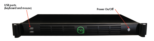
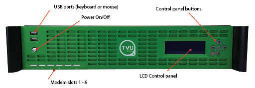
Model TE5500 front panel overview
The TVU MLink model TE5500 front panel features the following connections, indicators, and controls.
Note: USB ports on the front panel are intended to support only a keyboard and mouse. Do not connect USB modems, network adapters, and like devices into these ports.
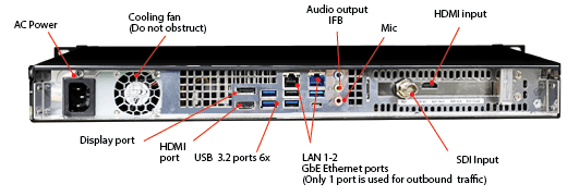
Model TE5500 rear panel overview
The TVU MLink model TE5500 rear panel features the following connections.
Note: The USB ports support up to four USB devices from any of the six ports.
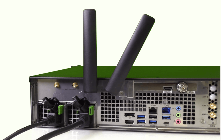
Model TE5700 front panel overview
The TVU MLink model TE5700 front panel features the following connections, indicators, and controls. The TE5700 ships with 3 standard LTE dome antennas to support 6 modems.
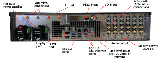
Model TE5700 rear panel overview
The TVU MLink model TE5700 and rear panel feature the following connections.
Note: The top left USB port supports WiFi while the bottom right port supports hotspot functionality (for TE5700 support only)
Before you begin
Complete the following procedures to set up the TVU MLink model TE5500 and TE5700 transmitters.
Refer to the front and rear panel overviews for MLink transmitter connection descriptions and locations to assist with the setup procedures. Contact TVU Support if you have any difficulties during the setup process.
MLink TE5500 transmitter setup procedure
Complete the following steps to set up the MLink model TE5500 transmitter. All input sources must be in a supported video format and frame rate:
- Connect the factory-supplied AC power cable to the MLink and AC power source.
- Connect a computer display connector to the rear panel display or HDMI output port to view real-time system status.
- Connect a TP-Link wireless card dongle to the top left rear panel USB port to enable WiFi if required.
- Connect a TP-Link wireless card dongle to the bottom right rear panel USB port to enable hotspot functionality if required.
- Connect an Ethernet cable to the left Ethernet port on the rear panel.
- Connect the HD/SD video source to the SDI or HDMI port on the back of the MLink. Refer to the rear panel overview diagram for the SDI input and HDMI input port locations.
Note: Supports up to 8 channels of embedded audio.
- TVU IFB and VoIP service are provided using the USB audio box connected to the receiver. Connect your audio equipment as appropriate.
MLink TE5700 transmitter setup procedure
Complete the following steps to set up the MLink model TE5700 transmitter:
Note: All input sources must be in a supported video format and frame rate.
- Connect the factory-supplied AC power cable to the MLink and AC power source.
- Connect the computer display to the rear panel display or HDMI output port to view real-time system status.
- If required, connect WiFi MIMO antennas to the top left WiFi connectors to support the MIMO mode configuration for LTE downloading (does not support uploading.)
- Connect an Ethernet cable to one of the two GbE Ethernet ports on the rear panel.
- Connect the antenna connector to the modem connection on the rear panel:
- LTE dome antenna (3 antennas) with two connectors. One antenna supports 2 modems and should be installed at least 20 centimeters apart.
- 5G modem antenna (one per modem) with four connectors. The 5G antenna should be installed at least 20 centimeters apart.

- Connect the HD/SD video source to the SDI or HDMI port on the back of the MLink. Refer to the rear panel overview diagram for the SDI input and HDMI input port locations.
Note: Supports up to 8 channels of embedded audio.
- TVU IFB and VoIP service are provided using the USB audio box connected to the receiver. Connect your audio equipment as appropriate.
MLink TE5700 front panel controls and operations
You will use the control panel buttons to access common functions on the device, such as switching receivers, transmitting modes, or triggering a live transmission.
The control panel button functions are as follows:
- Press the Left and Right arrows to switch between paired receivers or transceivers.
- Press the green check button to go live or to confirm an action.
- Press the Red X button to stop a live transmission or deny an action.
- Use the Up and Down arrows to switch between preset transmission modes.
Step 1 – Powering the TVU MLink TE5700 On and Off
Complete the following steps to power on/off and restart the MLink transmitter:
- To power On the TVU MLink, press the power button in the front panel’s left lower section.
The name and PID number of the unit displays on the MLink LCD screen during boot-up. - To power Off the TVU MLink, press and hold the power button down for more than four seconds.
Note: The TVU MLink will automatically restart if the power button is pressed and held in for less than four seconds.
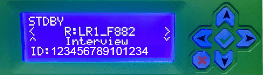
TVU MLink TE5700 front LCD panel and functions
The MLink front LCD display panel allows the user to view the status of the following functions:
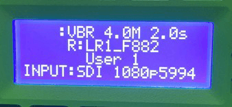
Transmission status monitor
The transmission status monitor displays the current transmission status of the paired TVU One, referred to as the “TVU Pack.”
- If the display is flashing “LIVE,” it indicates the transmission is live.
- If a camera or input source is not connected to the TVU MLink transmitter, the LCD panel displays “Online.”
- If a video source is detected, but the session is not Live, the display will show “STDBY” to indicate it is in Standby mode.
Receiver name
The currently selected receiver name is displayed on line 2.
Preset transmission mode
The transmission mode status for the selected receiver is displayed under the receiver name.
Input
The input source is displayed on line 4.
Using the TVU MLink controls and operations panel
Complete the following procedures in steps 2 through 4 to use the TVU MLink front panel controls and operations functions. The MLink status displays on the LCD screen.
Note: Refer to the following “LCD status display panel” figure unless otherwise indicated for this section.
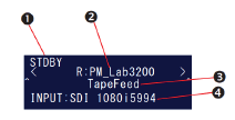
Figure reference: LCD status display panel
Step 2 – Choosing a transceiver
- Locate the currently selected transceiver’s name. Refer to callout ( 2 ) on the MLink “LCD status display panel” figure.
- To choose a preset transmission mode, use the controls and operations panel. Press the Left and Right arrows to scroll through and select the available receiver.
- Verify your change on the LCD panel.
The default preset transmission mode may be different for each receiver or transceiver. You may see the preset transmission mode change when switching between other receivers and transceivers.
Step 3 – Choosing a preset transmission mode
- Locate the preset transmission modes displayed under the receiver name. Refer to callout ( 3 ) on the MLink “LCD status display panel” figure.
- To choose a preset transmission mode, use the controls and operations panel Up and Down arrow keys to scroll through and select the desired option.
- Verify your change on the LCD display panel.
Step 4 – Going live with your transmission
- Before going “Live,” connect the camera or input source to the MLink transmitter. If a camera or input source is not connected, “Online” displays in the top left corner of the LCD panel.
- Verify that the camera or input source is connected. The LCD panel displays “STDBY” in the top left corner of the LCD panel. Refer to callout ( 1 ) on the MLink “LCD status display panel” figure.
- To go “Live,” press the green check mark button on the front control panel. The transmitter will prompt you to start a live transmission in the LCD display.
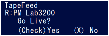
- To confirm, click the green check mark button once more.
- To deny the request, click the front panel controls red X button. The selected preset transmission mode and paired receiver name will display on the LCD panel.
- When the transmitter is in “Live” mode, the word “LIVE” (as shown in the go-live confirmation display) blinks in the top left corner of the LCD panel. The variable bitrate will also display in real-time next to the flashing “LIVE” indicator.
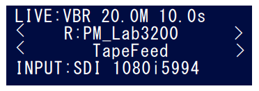
The selected preset transmission mode, paired receiver name, and input source are displayed.
- Press the red X button on the control panel to stop a live transmission. The unit will prompt you to stop the live transmission, as shown in the following figure.
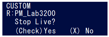
- To confirm that you want to stop the transmission, press the front panel’s controls’ green check mark button. Then, click the red X button on the front panel controls to deny the request.
- After the live transmission has stopped, the screen returns to (“STDBY”) mode.
Step 5 – Use the Display or HDMI port to view the Video preview and transmission status screen
To view a detailed view of the status screen, complete the following steps to connect a monitor to the Display or HDMI port on the TVU MLink rear panel:
- Connect a Display or HDMI monitor cable to the appropriate port on the TVU MLink to view the detailed status display screen.
- Connect a camera to the TVU MLink and power on both the camera and MLink devices. The Video Preview Transmission screen displays.
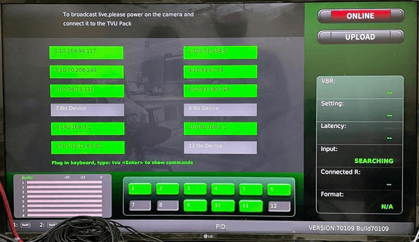
Video Preview Transmission screen
Refer to the following “Video preview transmission screen” figure and the live TVU MLink display status screen settings and descriptions list.
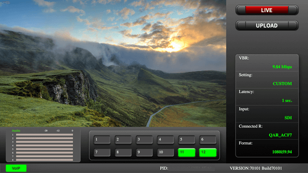
TVU MLink display status screen settings and descriptions:
- Input preview – Shows the live picture from the camera and captured in TVU MLink.
- Transmission status monitor – Provides the current transmission status of the TVU Pack. TVU MLink transmits a “Live” picture if the indicator is red. If the indicator displays black/gray, the TVU MLink is not transmitting live and is on “Standby.”
- File upload status monitor – Displays the progress of any file being uploaded from the TVU MLink’s SSD hard drive to the TVU Receiver.
Note: Uploading a file is not possible when the TVU Pack is in “Live” mode.
- Data card status monitor:
– Displays the current number and status of all data cards connected to the TVU MLink.
– The status of data cards connected to the Pack will appear as green, red, or black.
– The green status indicates that the data card is connected.
– The red status indicates that the data card is attempting to dial.
– The black status indicates there is no card.
- TVU MLink PID and firmware version information – Indicates the unit’s identifying PID and version number. Be sure to have this information available when contacting TVU customer support.
- Audio input level monitor – Dynamically displays a graphic indicator in color for the TVU MLink audio input level (DBFS).
- VoIP/IFB indicator – Indicates whether or not the IFB function is on. The small red IFB box indicates that the IFB function is enabled and connected. If the red box does not appear, IFB is not connected or is disabled.
Standby video input status screen
Refer to the following “Standby video input status screen” and the TVU MLink standby video status screen settings and descriptions list.
- Connection status:
– Displays the status and IP of each network connection. The status of data cards connected to the TVU Pack will appear green, red, or black.
– The green status indicates that the data card is connected.
– The red status indicates that the data card is attempting to dial.
– The black status indicates there is no card detected.
- Transmission status monitor – Provides the current transmission status of the Pack. TVU MLink transmits a “Live” picture if the indicator is red. If the indicator is black/gray, TVU MLink is not transmitting live and is on “Standby.”
- File upload status monitor – Displays the progress of any file being uploaded from the TVU MLink’s SSD hard drive to the TVU Receiver.
Note: Uploading a file is not possible when the TVU Pack is in “Live” mode.
- Data card status monitor:
– Displays the current number and status of all data cards connected to the TVU MLink.
– The status of data cards connected to the TVU Pack will appear green, red, or black.
– The green status indicates that the data card is connected.
– The red status indicates that the data card is attempting to dial.
– The black status indicates there is no card detected.
- VoIP/IFB indicator – Indicates whether or not the IFB function is on. The small red IFB box indicates that the IFB function is enabled and connected. If the red box does not appear, IFB is not connected or is disabled.
- TVU MLink PID and firmware version information – Indicates the unit’s identifying PID and version number and is used when contacting TVU customer support.
- Audio input level monitor – Dynamically displays a graphic indicator in color for the TVU MLink audio input level (DBFS).
Advanced Configuration
This section provides instructions for advanced configuration settings for hotspot, WiFi, modem, microwave, router, and BGAN configuration for the MLink model TE5700 transmitter.
TVU MLink system status monitoring and control using a Web browser on an iPhone or a smart mobile device
The TVU Transmitter’s operational status can be monitored, and various parts of the transmission can be controlled from a Web browser. This interface can be accessed using a standard web browser connected to the TVU MLink TE5700 hotspot USB port on the rear transmitter panel.
Connecting the MLink TE5500 to the internal hotspot (optional)
Complete the following steps to configure the TVU MLink transmitter to the internal hotspot using your iPhone or a smart mobile device:
- Connect the TP-Link WiFi dongle to the rear panel bottom right USB port.
- Search for the Hotspot on your iPhone/smart device, then, when prompted, enter the case-sensitive SSID:
- TVUPACK_XXXX
(Where X is the last 4 digits of the MLink’s PID) - The default password is the last 8 digits of the MLink PID
- All password characters are uppercase. The password can be changed in the Web UI if desired.
- TVUPACK_XXXX
- Connect to the SSID using your iPhone/smart device. Refer to the following “TVU MLink status; video and network screen” for examples of how the status screens display on a smart device Web browser.
- Once the connection is established, open a web browser and enter the following IP address in the address line to see the transmitter’s “System status”: http://192.168.4.1
- The MLink System Status panel will display.
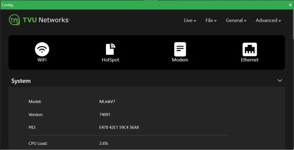
MLink System status panel overview
The System status panel provides access to the following information.
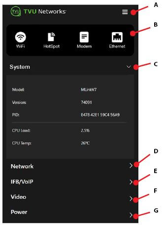
The MLink transmitter System status panel provides access to the following information:
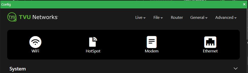
(A) MLink advanced operations icon – Tap the three-bar icon to open the advanced operations menu. This opens the Live, File,
General, and Advanced menu selection panels.. Refer to “MLink Advanced operations – Web interface controls” for more information.
(B) Configuration shortcut icons – These icons open the WiFi, HotSpot, Modem, and Ethernet configuration panels.
(C) System panel – Displays the MLink mode, version, PID, CPU capacity, and temperature.
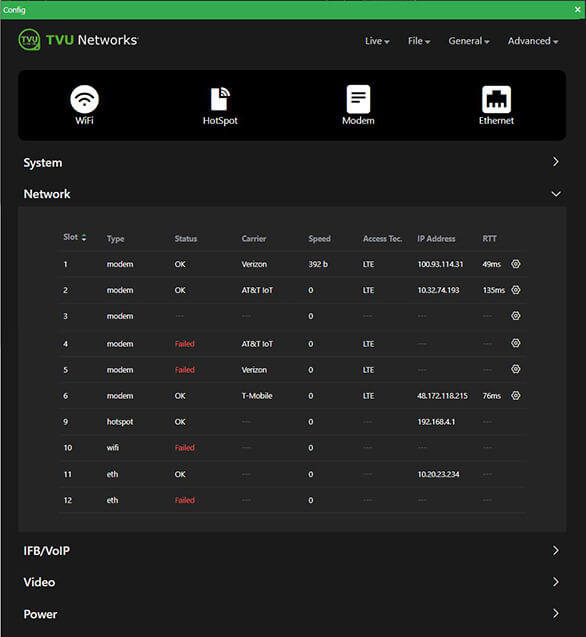
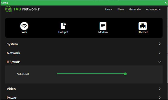
(D) Network panel – Modem card information including type, connectivity, and IP address all organized by slot number.
(E) IFB/VoIP panel – This panel allows the user to change the audio level of the IFB function.
(F) Video panel – Displays video transmission information and status.
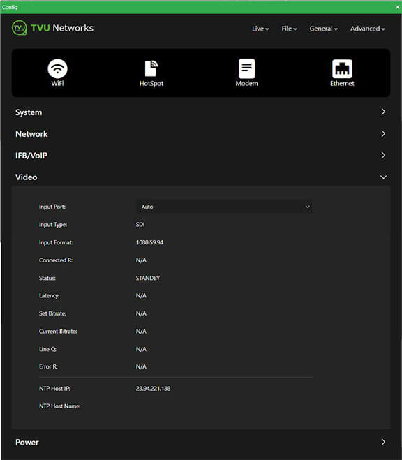
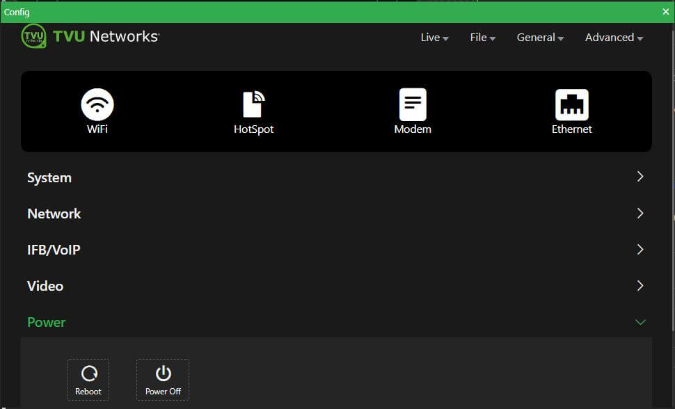
(G) Power panel – Contains the reboot and power off buttons.
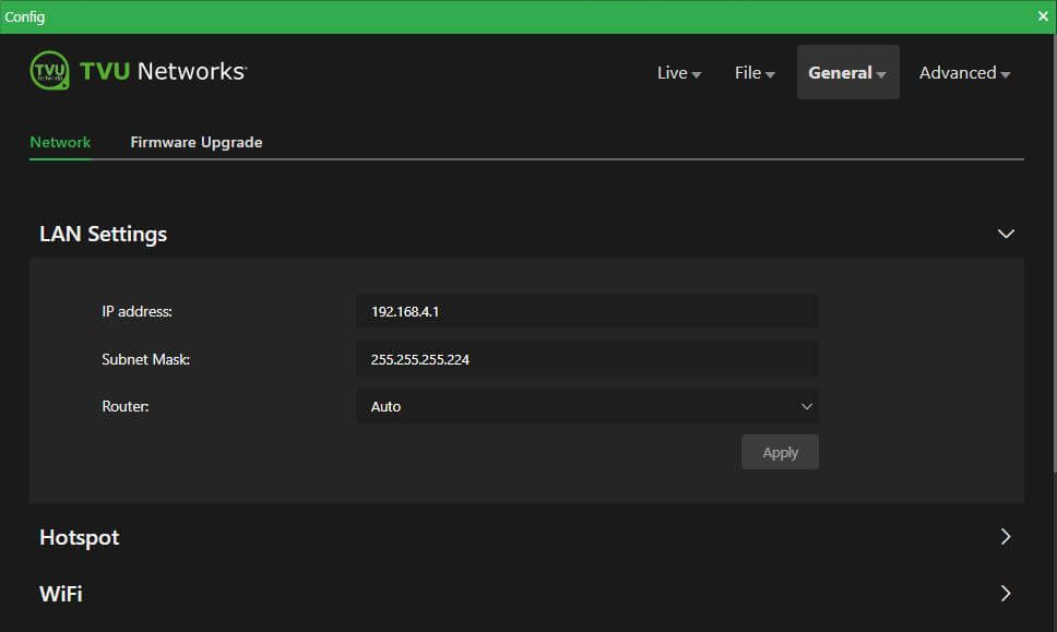
Network configuration
The Network configuration panel allows users to monitor and control all aspects of MLink network connectivity.
To open the Network configuration panel:
- Tap the General drop-down menu and select Network.
- The LAN Settings panel will display.

- In the LAN settings panel, set the MLink’s local LAN address. The default IP address is 192.168.4.1.
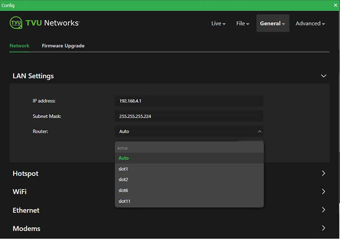
- Enter the Subnet Mask and select a Router setting from the drop-down menu; the default is Auto.
- Click Apply.
WiFi configuration
The WiFi panel provides configuration information and access to change the WiFi settings. The MLink TE5500 can optionally support multiple WiFi connections by purchasing optional hardware. For more information, contact TVU Networks support.
When multiple WiFi adapters are connected, you can scan available slots for WiFi adapters and configure the WiFi login information using the TVU MLink WiFi setup and configuration panel.
Configuring WiFi
To configure your WiFi settings:
- Click the WiFi icon.
- Scroll down to the WiFi panel.
- Enable the WiFi slider.
- Press the Scan button to display any available networks. The center panel displays available networks. Choose the desired network from the Devices panel.
- Click the “i” Information icon in the Devices list. The Security window opens.
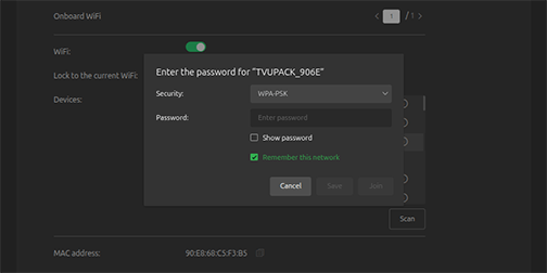
Note: The Security setting supports WPA2/WPA-PSK.
- Enter the Password.
- Click Join.
Hotspot settings
The Hotspot panel provides status information about clients connected through the hotspot.
Configuring hotspot
To configure your WiFi settings:
- Click the Hotspot icon.
- Scroll down to the Hotspot panel.
- Enable the Hotspot slider.
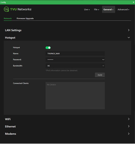
- To update the Password, edit the Password field.
The new password must be 8 characters. A system restart is necessary after changing the password. - The hotspot feature will enable a connected device to access the internet using one of the connected networks.
Note: Hotspot access allows FTP file transfers. If higher bandwidth is required, refer to “Router configuration settings.”
- The Connected Clients panel displays a list of devices that are connected to hotspots.
- To manually select the route taken (for example, a Hotel WiFi network), choose the path from the Connected Clients list. In the Bandwidth drop-down menu, choose 2.4G or 5G.
- Click Apply to save your changes.
Modem configuration
The Modem panel provides modem configuration information. Many cellular data cards are automatically detected by the TVU MLink transmitter and will self-configure. If this is the case, no further action will be required. However, if a data card requires configuration, you can use the Modem panel to configure it.
Note: For information about RPS Link and MLink v7 Model TE5700 antenna configuration, refer to “Antenna configuration RPS Link and MLink v7 model TE5700.”
To open the Modems panel:
- Click the Modem icon.
- Scroll down to the Modems panel.
- Continue to Configuring data cards.
Configuring data cards
There are two data card configuration methods, Auto and Manual.
Auto configuration
Data cards are “Auto” detected, and further configuration is not necessary.
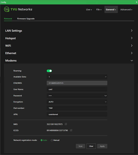
To confirm that the data cards are auto-detected:
- The Roaming slider is enabled by default.
- The Auto Network registration radio mode button is selected.
- Click the Available Slots drop-down list to confirm the list of available slots.
Manual configuration
When using the Manual data card configuration method, you can scan the list of available carriers and select the ones you want to configure. You can also change the APN or other details as needed.
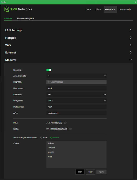
To “Manually” configure specific data cards:
- The Roaming slider is enabled by default.
- Click the Available Slots drop-down list to display a list of available slots for configuration.
- Enable the Manual Network registration mode radio button. The Carrier panel opens.
- Click the Scan button to refresh the Carrier list. Make a selection, then input the setting information provided by the carrier.
- Click Apply to save your changes.
Router configuration settings
In its standard deployment, the MLink can use one of its connections to support a data connection. When featured and deployed in router mode, the MLink can fully aggregate bandwidth.
Note: Router mode cannot be deployed in conjunction with a VLAN deployment, which is discussed in the next section.
VLAN Mode configuration
VLAN mode is used for hotspot pass-through, providing a single default connection.
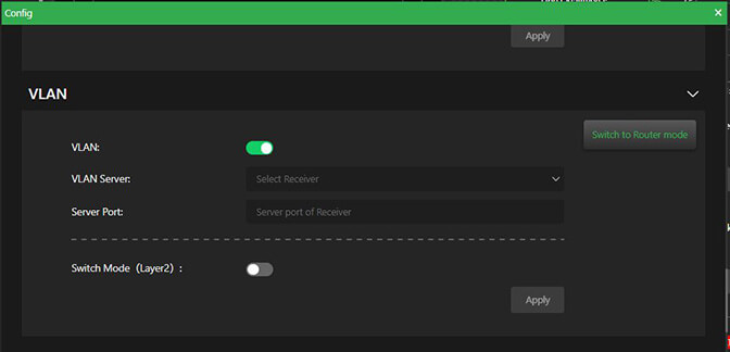
The VLAN settings are accessed on the network page. When disabled, it will offer to switch to router mode. Once enabled, the receiver, receiver port, and switch mode (layer 2) options will be displayed.
If neither router or VLAN only features are applied, none of these will be displayed.
To configure the pass-through in VLAN mode:
- Tap the General drop-down menu and select Network.
- The LAN Settings panel will display.
- The Router setting is set to Auto by default in the LAN settings panel.
- Scroll down to the VLAN panel.
Note: When the Router mode feature is enabled, the Switch to Router mode button appears in the VLAN panel.
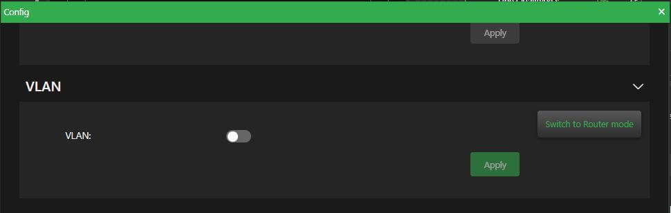
- Move the VLAN slider to the right to enable VLAN.
- Select a receiver from the drop-down menu.
- Enter the server port of the receiver.
- Enable Switch mode (layer 2) for a single LAN segment at both the MLink and Receiver locations. This is recommended for most users. If a separate LAN segment at each location is desired, leave this option disabled.
- Click Apply.
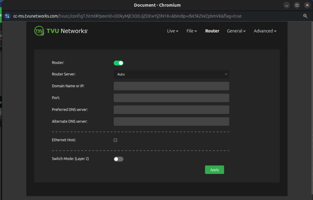
Router mode configuration
The TVU router has two pass-through data modes, VLAN and TVU Router mode. In VLAN mode, the MLink TE5700 can be used as an internet hotspot using one of the data connections. In the advanced TVU Router mode, the MLink TE5700 can utilize and make available the full aggregate bandwidth of the system for pass-through traffic. As a result, the bandwidth can often exceed 200 Mbps.
Note: TVU Router is an advanced licensed feature that must be activated by TVU Support before it can be used.
Router can be selected in the top menu when Router mode is enabled.
To configure Router mode:
- Click Router in the top menu.
- Click the Switch to Router mode button, then click Yes in the pop-up message box.
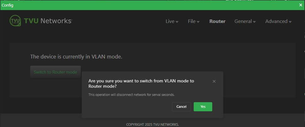
- The Router configuration panel opens. The Router slider is enabled by default.
- Click the Router Server drop-down menu and select your region.
- Click the Ethernet Host checkbox to enable services for up to 10 attached devices.
- Click Apply.
Note: Users can switch to VLAN mode by clicking the Switch to VLAN mode button.
TVU Router feature (Client connections)
If higher bandwidth is required when using a hotspot, the optional TVU Router feature can be enabled to allow clients connected to the MLink speeds of up to 200 Mbps.
- Click the General > Network tab and expand the LAN Settings panel.
- Select Auto in the Router drop-down menu.
- Enter the IP address and Subnet Mask, then click Apply.
- Scroll down on the Hotspot panel. Connected Clients will display in the Connected Clients device list.

Ethernet configuration DHCP IP
Ethernet settings are configured from the Receiver Control Config page.
Note: The DHCP IP method, the address is automatically generated and cannot be manually entered.
To configure your DHCP IP Ethernet settings:
- Click the Ethernet icon.
- Scroll down to the Ethernet panel.
- Click the Configure IPv4 drop-down menu and select the DHCP IP method.
- Click the Slot ID drop-down menu and select a slot number.
- Click Apply.
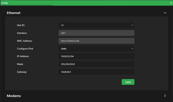
Ethernet configuration Static IP
To configure your Ethernet settings for a Static IP address:
- Click the Configure IPv4 drop-down menu and select the Static IP method.
- Select the Slot ID number from the drop-down menu.
- Enter a Static IP address in the IP Address field.
- Enter the Subnet Mask in the Mask field.
- Enter the Gateway in the Gateway field.
- Click Apply.
Antenna configuration RPS Link and MLink v7 model TE5700
This section provides antenna configuration procedures for the RPS Link, MLink v7, and Rack Router v2 (Models RE975/980/990)
RPS Link and MLink v7
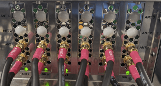
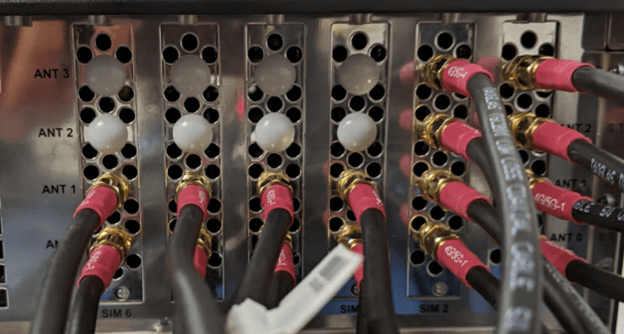
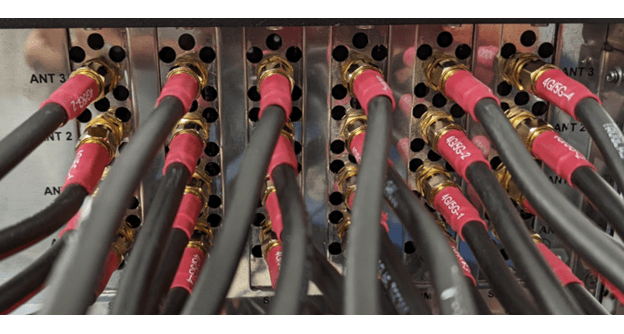
To configure antennas for the RPS Link and MLink model TE5700 unit with 6x 4G/LTE modem configuration, complete the following steps:
- Connect a 4G/5G external antenna SMA connector to ANT 0 on all 6 slots.
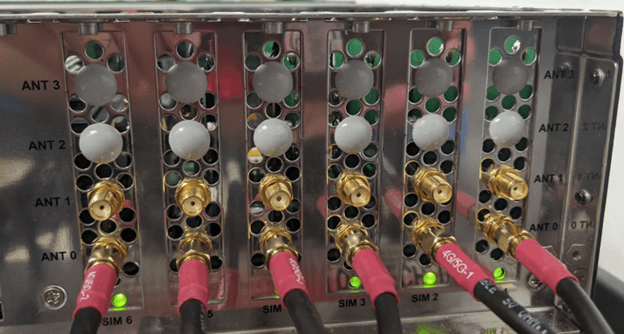
- For RPS Link and MLinkV7 (TE5700) unit with 2x 5G modem and 4x 4G/LTE modem configuration, connect a 4G/5G external antenna SMA connector to ANT 0, ANT 1, ANT 2, ANT 3 on slot 1 and slot 2 for 2x 5G modems, and connect a 4G/5G external antenna SMA connector to ANT 0 on slot 3, slot 4, slot 5, slot 6 for 4x 4G/LTE modems.
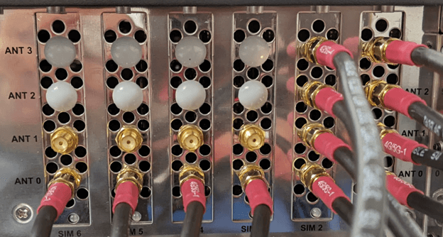
Notes:
- The 5G antenna is compatible with 5G modems and 4G/LTE modems, whereas the 4G/LTE antenna can only be used with 4G/LTE modems but not 5G modems.
- In addition, by connecting a 4G/5G external antenna SMA connector to the ANT 0 port for a 4G/LTE modem, the user has the option to connect a 4G/5G external antenna SMA connector to the ANT 1 port for a 4G/LTE modem. Meaning both ANT 0 and ANT 1 ports can be used for the antenna connection. However, connecting the ANT 1 port on both RPS Link and MlinkV7 (TE5700) product lineup is optional and not mandatory.
Rack Router v2 (RE975/980/990)
To configure the Rack Router V2 unit with 6x 4G/LTE modem configuration, also known as RE975 unit, complete the following steps:
- Connect a 4G/5G external antenna SMA connector to ANT 0, and ANT 1 on all 6 slots.
- To configure a Rack Router V2 unit with 2x 5G modem and 4x 4G/LTE modem configuration, also known as RE980 unit, connect a 4G/5G external antenna SMA connector to ANT 0, ANT 1, ANT 2, ANT 3 on slot 1 and slot 2 for 2x 5G modems, and connect a 4G/5G external antenna SMA connector to ANT 0, ANT 1 on slot 3, slot 4, slot 5, slot 6 for 4x 4G/LTE modems.
- For a Rack Router V2 unit with 6x 5G modem configuration, also known as RE990, connect a 4G/5G external antenna SMA connector to ANT 0, ANT 1, ANT 2, ANT 3 on all 6 slots.
Advanced transmitter operations – Web interface controls
Advanced operations using an iPhone, smart device or laptop
Note: There are two methods you can use to access the Mlink Advanced operations menu selections. The instructions in this chapter will show laptop display examples.
Method 1
To access the Advanced operations menu using an iPhone or smart device:
- Tap the three-bar icon to open the advanced operations panel.
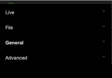
- Advanced operations are categorized in four drop-down menus: Live, File, General, and Advanced. The following sections will address all four menus.
Method 2
To access the Advanced operations menu using a laptop:
- Advanced operations are categorized in four drop-down menus. They are located at the top right of the system status screen: Live, File, General, and Advanced. The following topics will address all four menus.
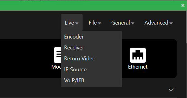
Live menu operations
The Live menu operations include the following settings:
- Encoder
- Receiver
- Return Video
- IP Source
- VoIP/IFB
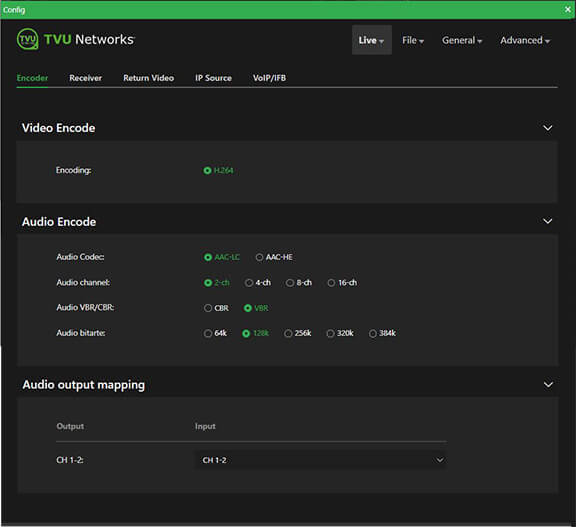
Live – Encoder
Use the Encoder panel to configure video, audio encoding, and audio output mapping.
To access the Encoder panel:
- Click the Live menu, then tap Encoder.
Encoder status and controls
Note: If the optional HEVC license is purchased, both H.265 Interview and H.265 Fast Motion mode will be available as selections.
To configure Live video and audio encoding settings:
- Select a Video Encoding mode that suites your application based on the following criteria:
- The encoding mode default is H.264.
- If the optional HEVC license is purchased, both H.265 Interview and H.265 Fast Motion encoding modes will be available as selections.
- Select the H.265 Interview radio button for shots containing limited motion, such as stand-ups or fixed shot interviews.
- Use the H.265 Fast Motion radio button to optimize compression for video containing significant motion elements, such as sports video containing high motion or fast pans and zooms.
- Select your Audio Encode panel configurations.
- Select an Audio output mapping from the drop-down menu.
Live – Receiver
Use the Receiver panel to configure your receivers. The Receiver panel displays the receiver status and controls.
To access the Receiver panel:
- Click the Live menu, then Receiver.
- The Receiver panel opens.
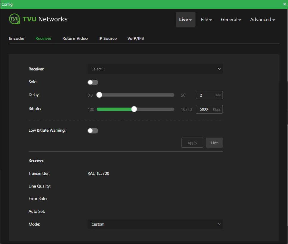
Receiver status and controls
To select an alternate receiver, view its status, and set up and control a ”Live” transmission:
- To view and select a different receiver, click the Receiver Select R drop-down menu and select a receiver from the list.
- Enable the Solo slider if you want a specific MLink to only display ‘Online” on the receiver you selected from the Receiver Select R drop-down menu.
- In the Delay field, enter the desired transmission delay.
- In the Bitrate (kbps) field, enter the desired transmission bitrate.
- To enable the Low Bitrate Warning, enable the slider and enter a Low Bitrate Threshold.
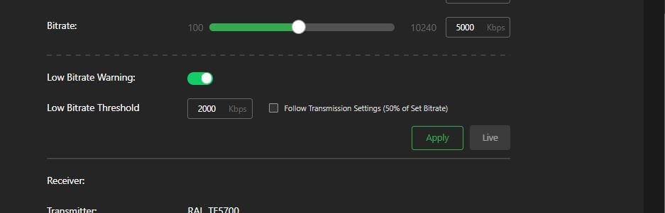
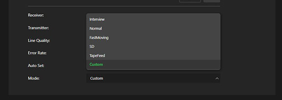
- Click the Mode drop-down menu and select a mode that suits your application:
- Interview
- Normal
- FastMoving
- SD
- Tapefeed
- Custom
- Click the Apply button to save your changes.
- To Start or Stop the live transmission, click the Live button.
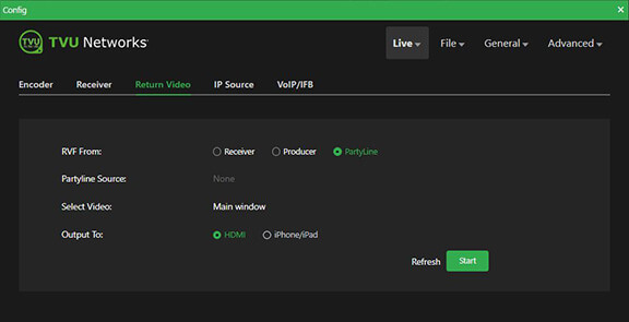
Live – Return Video
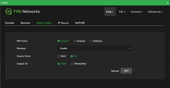
The built-in HDMI output uses 720p by default, but can provide up to 1080p resolution and allows a user to send a confidence monitor or SDI source back to crews in the field. This on-board feature can now support viewing the return video feed using an iPhone and iPad. Contact TVU Support for 1080p configuration.
To access the Return Video panel:
- Click the Live menu, then Return Video.
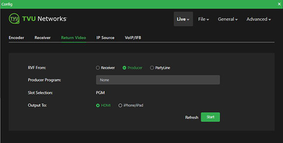
- The Return Video panel opens. There are three RVF From selections: Receiver, Producer, and Partyline.
- Select where you want the RVF to come from. If you choose Receiver, select a Receiver from the drop-down menu.
- Select where your source is coming from.
- Select where you want your Output to go and click Start.
RVF from Producer selection:
RVF from Partyline selection:
Live – IP Source
The IP Source panel allows users to select an outside IP source or camera source from the selection window with which to go live.
To access the IP Source panel:
- Click the Live menu, then IP Source.
- The IP Source panel opens.
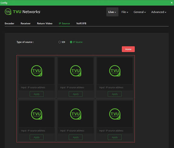
- Click the SDI or IP Source radio button.
- Click the SDI radio button to display the camera source that is connected to the MLink.
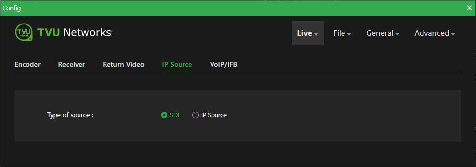
- Click the IP Source radio button to add an IP Source with which to go live.
- Enter the valid IP address in the field under an available source selection with which you want to go live, then click the Apply button to save your source selection.
- Click the Home button to send all IP sources in one matrix picture to the TVU MLink.
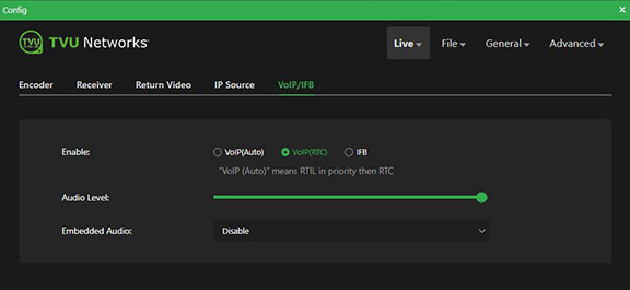
Live – VoIP/IFB
The VoIP/IFB panel enables you to:
- Integrate VoIP/IFB audio in/out and from/to the transceiver.
- Integrate IFB audio from the transceiver to the MLink.
To access the VoIP/IFB panel:
- Click the Live menu, then VoIP/IFB.
- The VoIP/IFB panel opens. VoIP(Auto) is the default.
Live menu > VoIP/IFB panel – VoIP(RTC)

Live menu > VoIP/IFB panel – IFB
- Make the appropriate selections.
- Select an Embedded Audio if applicable.
- Enable Bluetooth if applicable.
- Adjust the Audio level slider if applicable.
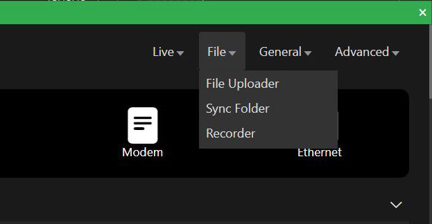
File menu operations
The File menu is located at the top right of the system status screen.
The File menu operations include:
- File Uploader
- Sync Folder
- Recorder
To access the Advanced operations menu using an iPhone or smart device:
- Tap the three-bar icon to open the advanced operations panel.
- The Advanced operations panel opens. Tap File > File Uploader.
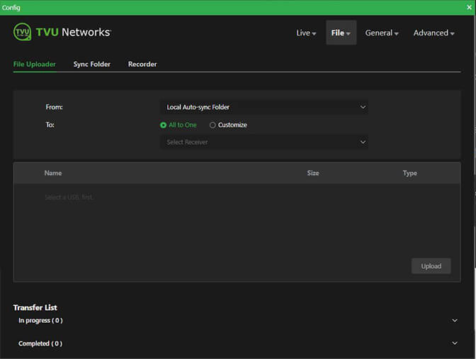
File – File Uploader
The File Uploader panel allows you to upload files to a specified receiver using the Auto Sync feature.
The Auto Sync feature lets you to transmit wireless digital content from the MLink to the TVU receiver using a USB memory stick.
The MLink will auto-detect the memory stick and automatically transfer the contents to its internal SSD hard drive. The content will then be available for wireless transmission to the TVU receiver.
To access the File Uploader panel:
- Click the File menu, then File Uploader.
- The File Uploader panel opens.
- Choose where you want your file uploaded From.
- Choose where you want your file uploaded To.
- Tap the Upload button.
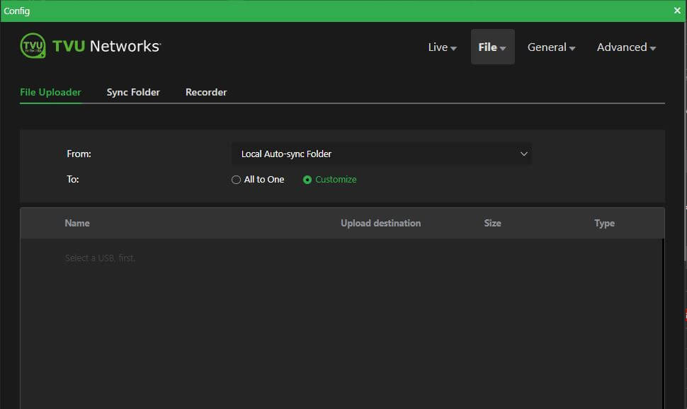
- If you select the Customize radio button, choose where you want your file uploaded From.
- Tap the Upload button.
Note: For more information, refer to the “File-Based Workflows Reference” document’s topic “Using the Auto Sync feature with a USB stick.”
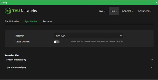
File – Sync Folder
The Sync Folder panel enables users to transfer and sync files to a specified receiver and monitor the progress.
To access the Sync Folder panel:
- Click the File menu, then Sync Folder.
- The Sync Folder panel opens.
- Select a receiver to sync your files to. The default is the last receiver you went live with.
- Enable the Set as Default slider to set a specific receiver as your default.
Note: For more information, refer to the “File-Based Workflows Reference” document’s topic “Auto Sync feature.”
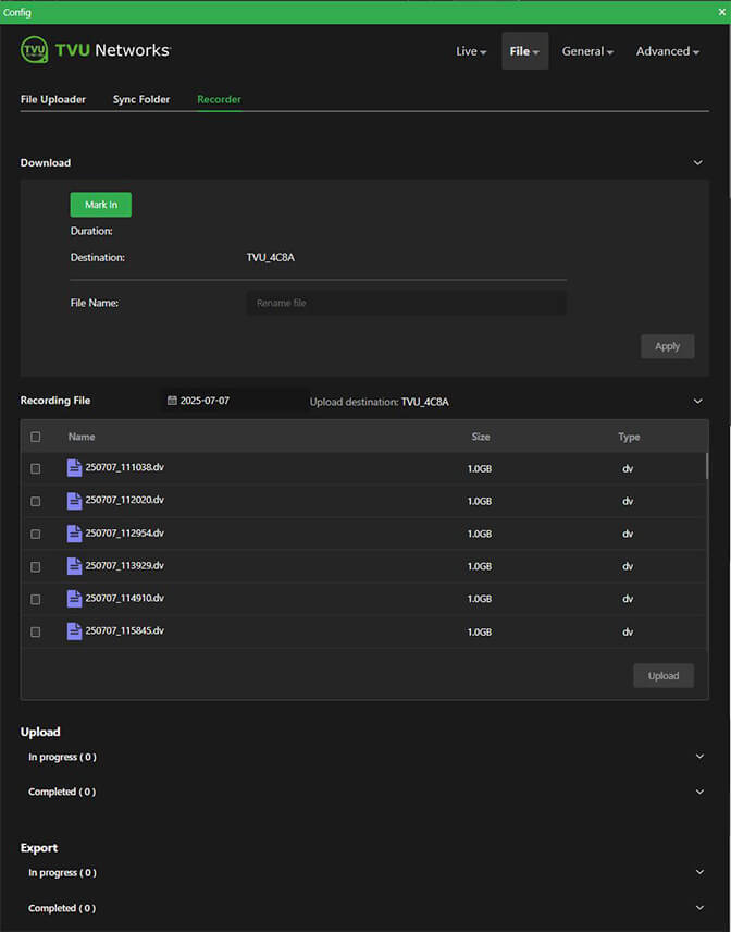
File – Recorder
The Recorder tab allows users to select, mark, download, rename, and upload recorded files.
To access the Recorder panel:
- Click the File menu, then Recorder.
- The Recorder panel opens.
Note: Refer to the File-based Workflow Reference guide “Working with recorded content” topic for detailed information about how to use the Record feature.
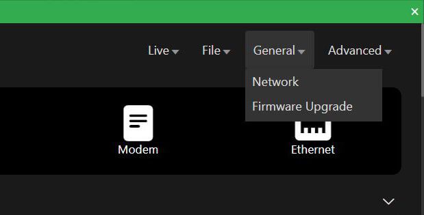
General menu operations
The General operations menu include:
- Network
- Firmware Upgrade
To access the Advanced operations menu using an iPhone or smart device:
- Tap the three-bar icon to open the advanced operations panel.
- The Advanced operations panel opens. Tap General > Network.
General – Network
The Network panel enables users to:
- Configure LAN settings
- Users can complete the Hotspot configuration for client connections in the Hotspot panel.
- Create additional WiFi connections with additional USB WiFi adapter support. Users can enable or disable WiFi from the UI. The WiFi will automatically redial if network connectivity fails.
- Configure Ethernet
- Configure Modems
To access the Network panel:
- Click the General menu, then Network.

- The Network panel opens.
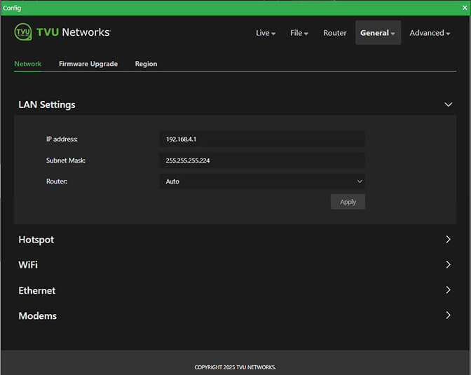
- Click the Router drop-down menu and make a selection. Auto is the default.
Note: The Network configuration information is explained in “Network configuration.”
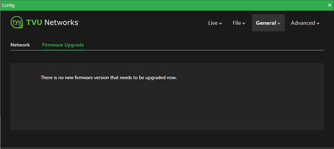
General – Firmware Upgrade
You can check for firmware updates in the Firmware Upgrade panel.
To access the Firmware Upgrade panel:
- Click the General menu, then Firmware Upgrade.
- The Firmware Upgrade panel opens.
- The following message displays when a firmware update is not available.
- When a new Firmware version is available, you will have the option to upgrade from this panel.
Advanced menu operations
The Advanced menu include:
- Progressive Download
- SelfCheck
- NTP
- MediaMind Story
- MediaMind Setting
- Messages
- Token
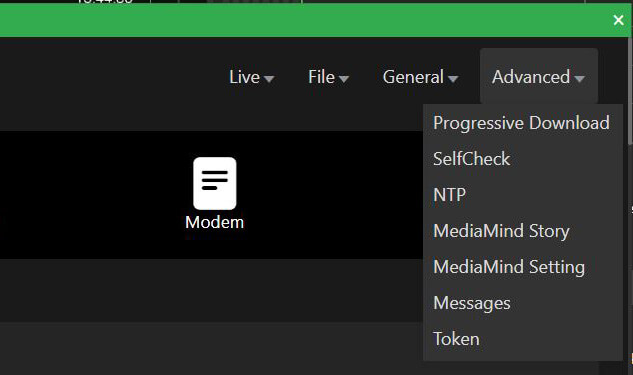
To access the Advanced menu using an iPhone or smart device:
- Tap the three-bar icon to open the Advanced operations panel.
- The Advanced operations panel opens.
Advanced – Progressive Download
The Progressive Download feature is enabled in the Progressive Download panel and is controlled by using the record button on the video camera (e.g. Camcorder).
To access the Progressive Download panel:
- Click the Advanced menu, then Progressive Download.
- The Progressive Download panel opens.
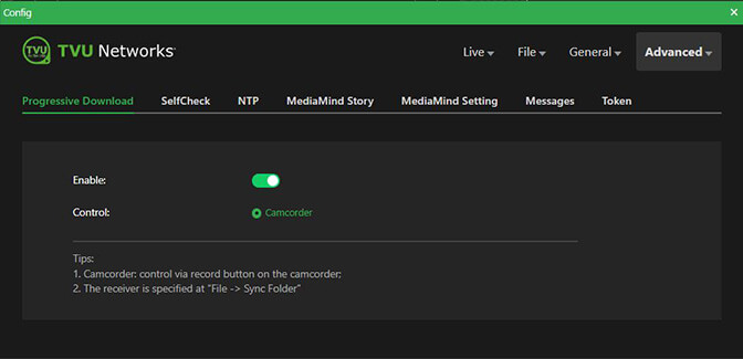
- To use the Progressive Download feature, Move the Enable slider to the right until green.
- The receiver is specified in the File menu > Sync folder.
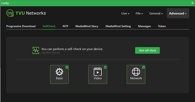
Advanced – SelfCheck
The Self Check panel enables you to perform a self check on your devices’ basic, video, and network health status.
To access the SelfCheck panel:
- Click the Advanced menu, then SelfCheck.
- The SelfCheck panel opens.
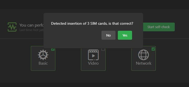
- Click one or all Basic, Video, and Network checkboxes, then the Start self-check button to run a health check on your device.
- Click Skip or Yes to the following prompt.
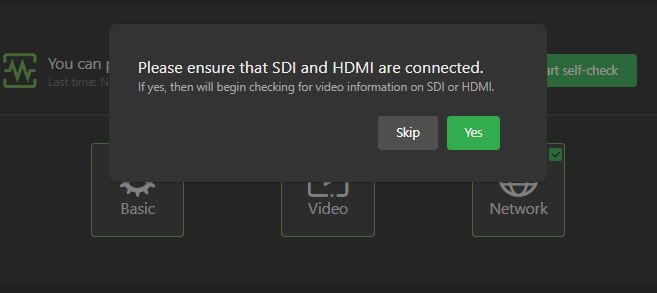
- Click No or Yes to the following prompt.
- Progress will be displayed during the self check process.
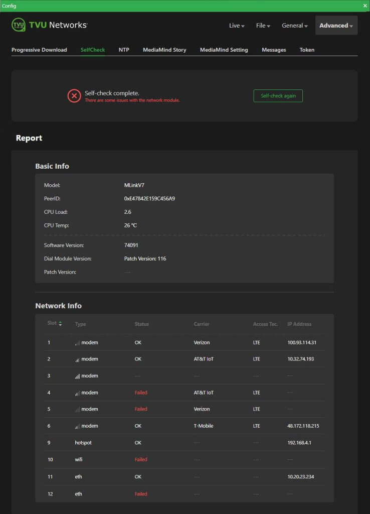
- After the SelfCheck completes, a Report is generated and will display in the SelfCheck panel.
- Any issues display in red. After mitigating flagged issues, you can click the Self-check again button.
Advanced – NTP
The NTP panel enables users to lock and synchronize a NTP host IP to the domain controller.
To access the NTP panel:
- Click the Advanced menu, then NTP.
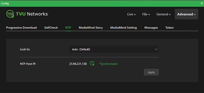
- The NTP panel opens.
- The Lock to Auto (Default) selection will lock to the closest available Host IP.
- The NTP Host IP should display “Synchronized” in green.
Advanced – MediaMind Story
The MediaMind Story panel allows you to add a Story name to a progressive download file.
To access the MediaMind Story panel:
- Click the Advanced menu, then MediaMind Story.
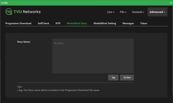
- The MediaMind Story panel opens.
- Enter a Story Name.
- Click Tag to include the Story Name in the Progressive Download file name.
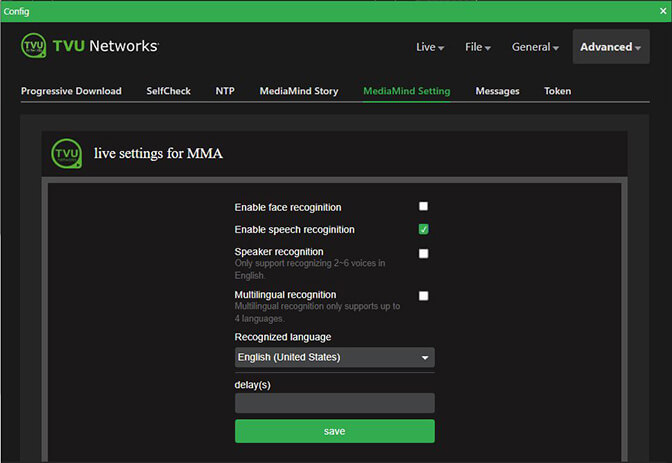
Advanced – MediaMind Setting
The MediaMind Setting panel enables you to configure live settings for face, speech, and speaker recognition up to four languages when you are using the TVU MediaMind Appliance (MMA) service.
Whether it is a live stream, an IP video stream, or a video file, the TVU MediaMind Appliance (MMA) uses AI technology to automatically generate metadata, organize, and search for content.
To access the MediaMind Setting panel:
- Click the Advanced menu, then MediaMind Setting.
- The MediaMind Setting panel opens.
- Configure your live settings for MMA and click Save.
Advanced – Messages
The Messages panel enables you to send and receive messages between the MLink and transceivers.
To access the Messages panel:
- Click the Advanced menu, then Messages.
- The Messages panel opens.
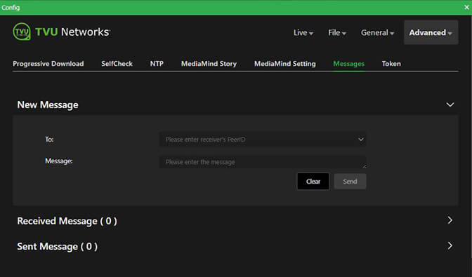
- In the To field, enter the recipient’s TVU receivers’ PID.
- Enter your message in the Message field and tap the Send button.
- Expand the Received Message caret to view messages that were received by the MLink.
- Expand the Sent Message caret to view messages that were sent by the MLink.
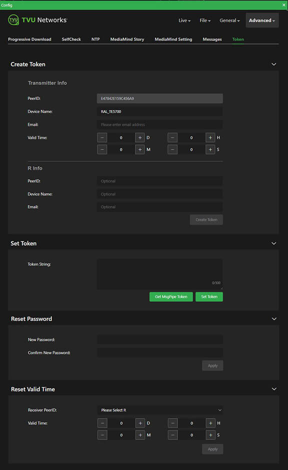
Advanced – Token
The Token panel allows you to create and configure tokens. Tokens are used to allow a recipient temporary access to your device.
To access the Token panel:
- Click the Advanced menu, then Token.
- The Token panel opens.
- Click Create Token.
- Enter the device PID. The device name automatically populates.
- Enter the recipient’s email address.
- Set up a Valid Time range: (D) Days, (H) Hours, (M) Minutes, and (S) Seconds for the token to be active.
- Click Create Token.
- To Reset the Password, enter and confirm the new password and click Apply.
- To Reset the Valid Time, select the receiver from the drop-down menu, set the Valid time, then click Apply.
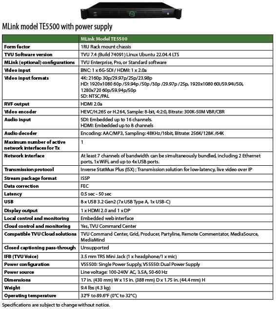
Product Specifications:
© Copyright 2025 TVU Networks Corporation. All rights reserved in all media.
Document Part Number: TVU MLink TE5500 and TE5700 QSUG Rev E EN 07-2025