Contents
- Introduction, setup, and base operation
- Features
- Guide contents
- TVU Nano router 5G kit
- Front panel components
- Rear panel components
- Hardware installation and connections
- Network connection and configuration
- Product configuration – Web UI
- Home tab
- General settings tab
- Router Server modes
- WAN IP and LAN settings
- Hotspot configuration
- WiFi configuration
- Intelligent Speed Limit
- Advanced Settings
- LAN settings
- P2P settings
- Modem configuration
- Transparent Mode
- Typical P2P deployment scenarios
- P2P Configuration interface
- NAT/No NAT server switching
- Horizontal Expansion and Remote Backup server support
- L2-Switch mode
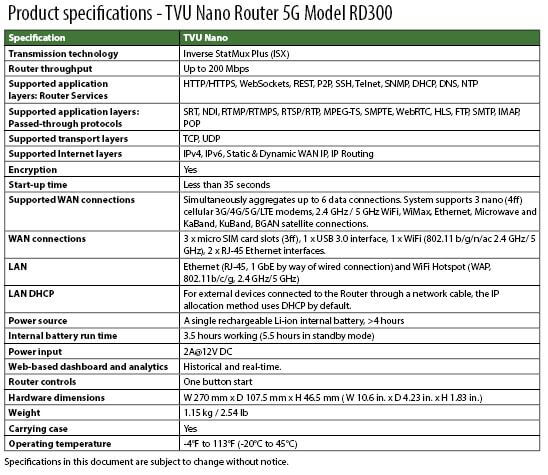
- Product specifications
TVU Nano Router (5G) Model RD300 Setup and User Guide

Product overview
The TVU Nano Router 5G (Model: RD300) is a compact, ultra-portable enterprise-grade 5G router engineered for high-bandwidth, resilient, and low-latency field connectivity. Built to aggregate multiple cellular signals simultaneously using TVU’s advanced multi-carrier bonding technology, the Nano Router ensures continuous broadband internet access for live video transmission, emergency response, remote field operations, and mobile offices.
Key hardware and cellular capabilities
Triple-Slot 5G Modem Architecture:
Features 3 independent 5G modem slots supporting enterprise-grade cellular modules (Quectel RM500Q / RM520N-GL). Users can insert SIM cards from up to three different mobile carriers simultaneously (e.g., Slot 1: Carrier A, Slot 2: Carrier B, Slot 3: Carrier C) to maximize coverage and bandwidth redundancy.
High-Throughput Performance:
Delivers real-world bonded network throughput with average performance exceeding 248 Mbps download and 115 Mbps upload under standard 3-carrier bonded operations.
Flexible Interfaces:
Includes high-speed Ethernet LAN and WAN interfaces, external high-gain 5G antennas, and built-in Wi-Fi module supporting local client device connections and mobile hotspots.
Features
The TVU Nano Router has a small, lightweight, and robust hardware design and functions to fit the needs of any live broadcaster. The built-in battery allows field staff to transport the router on location and is easily installed into a standard rack inside a vehicle or control room.
The TVU Nano Router supports simultaneous connections to multiple networks, including mobile cellular networks, satellite, microwave, WiFi, and Ethernet. The TVU Nano Router runs on the TVU platform and includes the following functions and features:
- Simple Worry-Free Operation: The TVU Nano Router can be configured in the field and boots up in less than 35 seconds with a push of a button.
- Power source: The TVU Nano Router comes with a single, rechargeable Li-ion internal battery and a 2A 12V DC power adapter. The internal battery run time supports 3.5 hours of working and 5.5 hours of standby power.
- Multilingual Web Management UI: Intuitive browser-based management interface with instant English and Simplified Chinese language switching.
- Real-Time Diagnostics: Dashboard view providing live signal strength per slot, connected client lists, bandwidth usage meters, and server connection status.
- Integrated WiFi & Hotspot: Operates in standard Wi-Fi router mode or Hotspot mode (including Switch Mode operation) to connect laptops, mobile phones, and field equipment wirelessly.
- External Hotspot antennas: The TVU Nano Router can be configured using the TVU Router Hotspot antennas and the Web user interface. The TVU Router configuration interface can be accessed using a standard web browser.
- LAN Support: Ethernet (RJ-45, 2 GbE connections) and WiFi Hotspot (WAP, 802.1 1b/g/n/ac, 2.4 GHz / 5 GHz.
- Supported WAN connection modes allow aggregation and bonding of multiple network paths:
- Simultaneous Aggregation (Up to 6 Data Connections):
- ISX Bonding Technology: The router uses TVU’s Inverse StatMux (ISX) protocol to aggregate bandwidth simultaneously across up to 6 data connection sessions (combining internal 5G cellular modems, WiFi WAN, and Ethernet WAN links) into a single, high-reliability connection tunnel.
- 3× Micro SIM (3FF) 3G/4G/5G LTE Cellular Modems:
- Internal Modems: Features 3 embedded cellular modem slots (Slots 1, 2, and 3) equipped with 5G modules (e.g., Quectel RM500Q or RM520N-GL) supporting 5G NR, 4G LTE, and 3G fallback networks.
- SIM Format: Accommodates 3× Micro-SIM (3FF) cards for multi-carrier cellular bonding.
- Supported External Network Types:
- TVU’s ISX protocol is IP-connection agnostic and natively supports bonding across all of the following WAN sources:
- WiFi WAN: Dual-band 2.4 GHz / 5 GHz Wi-Fi (802.11a/b/g/n/ac) client mode connectivity.
- Wired Ethernet: Gigabit Ethernet WAN connection via RJ-45.
- Satellite Networks: Ka-Band, Ku-Band, BGAN, and LEO satellite networks (e.g., Starlink).
- Wireless Data Links: WiMAX, Microwave, and Mesh networks.
- Simultaneous Aggregation (Up to 6 Data Connections):
- Intelligent Speed Limit: Custom bandwidth controls and QoS speed limiting per device or overall network to prevent congestion during bandwidth-constrained operations.
- Advanced Networking options: Transparent Mode & L2-Switching, P2P Support, Hostname Mapping, and Modem Parameter Control
- High-speed Internet access: Multiple available links can be aggregated including 3 built-in 4G/5G modules, 1 external 2.0 USB module, 1 network cable, and 1 WiFi.
About this guide
This user guide provides detailed information about the following topics:
- TVU Nano Router components
- Hardware installation and connections
- Setting up the TVU Nano Router
- Advanced operations
- Product specifications
Before you begin
Before you begin setting up the TVU Nano Router, identify the devices you intend to use with the unit, including cables, power sources, modems, and unit components.
TVU Nano router 5G kit
The TVU Nano router 5G kit comes with the following components:
- 1x Nano router device
- 12x 4G/5G antennas
- 4x WiFi frequency antennas
- 3x Built-in 4G/5G modules
- 1x WiFi hotspot
- 2x Ethernet (LAN) ports
- 1x External USB module
- 1x Network cable
- Power supply and 1x 1.2m power cable
- Carrying case
- 1U rack tray (optional)
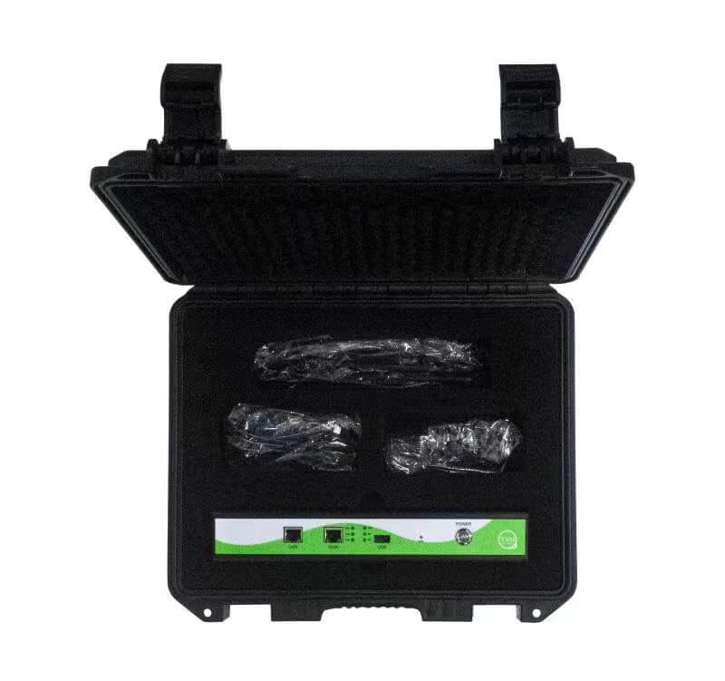
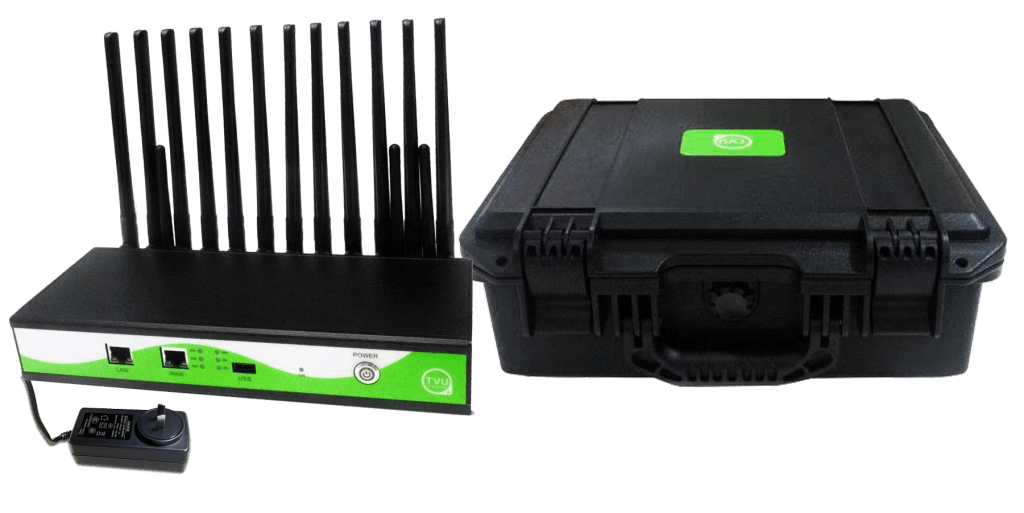
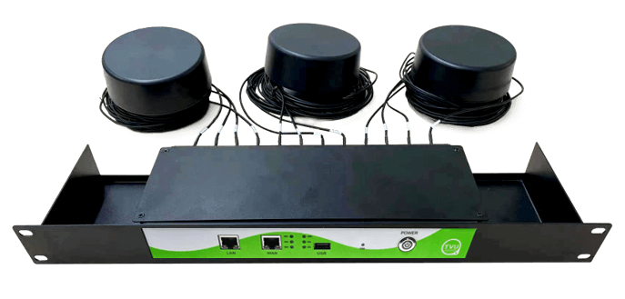
Note: The Ethernet connector is not included and must be customer supplied.
Front panel components
The TVU Nano router front panel features the following components.
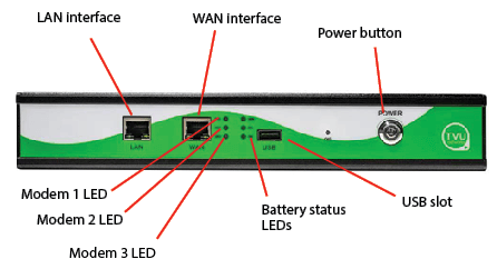
The front panel components and functions are as follows:
Battery status LED – Battery status indicator:
- Displays the percentage of remaining battery capacity at 100%, 60%, or 20%.
SIM indicator LEDs – SIM card LEDs 1, 2, and 3 display embedded cellular modem status indicators:
- When the indicator is not flashing, the SIM card is ready.
- When the indicator is flashing, there is wireless traffic.
- When the indicator is off, there is no wireless traffic.
LAN interface – Can be changed to WAN and aggregated:
- DHCP is open by default.
WAN interface – Can be changed manually to LAN to enable more visitors.
USB interface – Supports a USB wireless modem or USB to Ethernet.
Power button – To release the power button, press the power button to power ON the Nano:
- Press the power button for 5 seconds to Power off the Nano.
- Press the power button for 10 seconds to shut down the nano.
Rear panel components
The TVU Nano router rear panel includes the following components and functions.
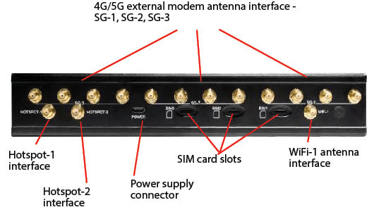
The rear panel components are as follows:
3x-5G Modem board SIM slots – Nano SIM cards:
- From right to left: SIM1, SIM2, and SIM3
- All three modems support the 5G network
External modem antenna interface – SG-1, SG-2, and SG-3 4-pin:
- The 4-pin antenna’s shipped with the router are full frequency and can be connected to any antenna.
- If you use a narrow frequency antenna with a different pin configuration, connect the antenna from left to right (i.e.) LMH, MH, LMH, and MH.
WiFi antenna (1x) – Used for an external WiFi signal to aggregate bandwidth:
- The WiFi-1 and WiFi-2 correspond to the WiFi-2 antenna.
- The WiFi antenna can also be used for the hotspot.
Hotspot antenna (2x) – Used to enable the routers hotspot:
- For hotspot-1 and hotspot-2, use two antennas.
- Set to 2.4 GHz by default.
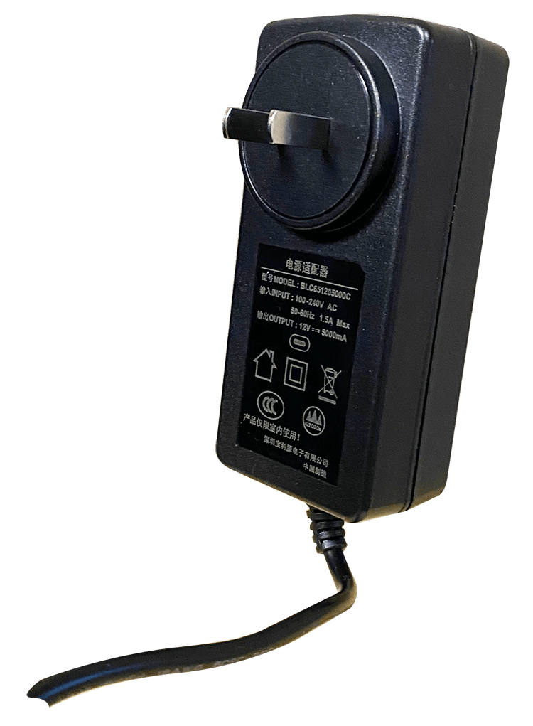
Charging the TVU Nano Router battery
To charge the internal battery complete the following steps:
- Connect the provided power supply to the Power input on the unit’s rear panel.
- Attach the other end of the connector to the electrical power outlet.
- The battery charge indicator LEDs display a percentage of battery capacity on the front panel at 100%, 60%, and 20%.
Note: Charging time will take approximately 1 hour. It is recommended that the Nano is powered off when charging the battery. The battery status LEDs display the percentage of remaining capacity on the front panel.
Hardware installation and connections
To set up the TVU Nano router, complete the following steps:
SIM card installation and removal:
- Insert a Micro SIM card (3ff) into the card slots SIM-1, SIM-2, and SIM-3 in the orientation printed on the rear panel until they click into place.
- Best Practice: Use SIM cards from different cellular carriers across the 3 slots to maximize bonded 5G/4G bandwidth and redundancy.
- Note: Ensure SIM cards are inserted prior to powering on or modifying roaming settings to avoid SIM detection errors.

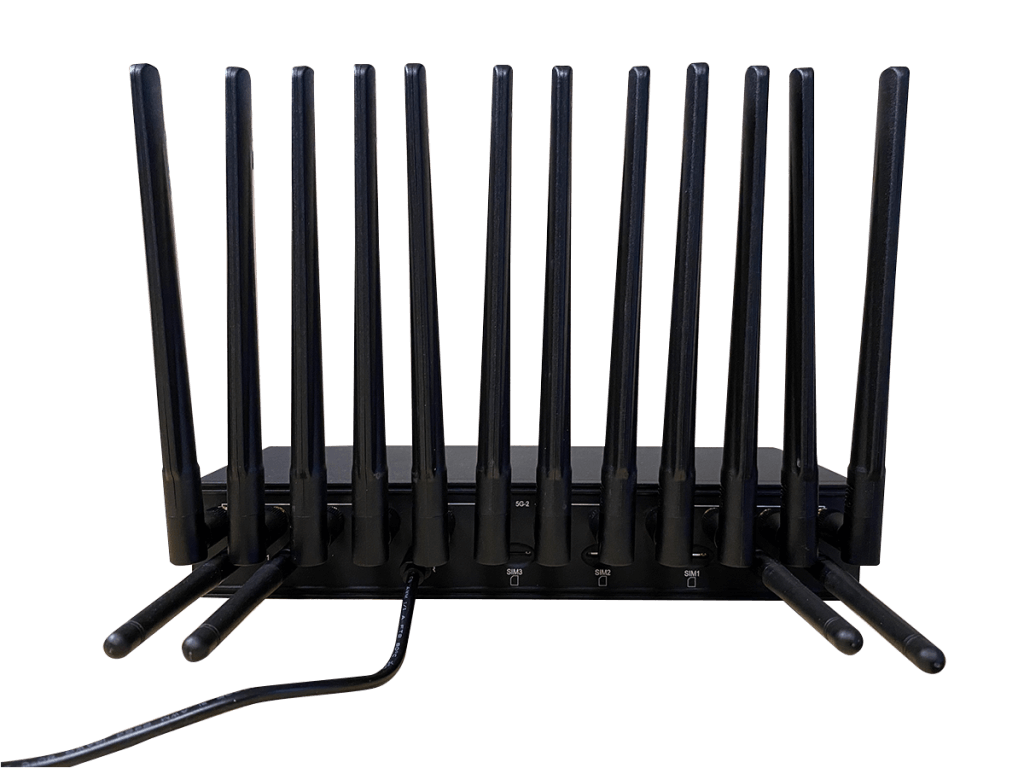
- Attach the external 5G cellular antennas to the SMA antenna terminals corresponding to the 3 modem slots (supporting RM500Q / RM520N-GL modems).
- Attach the WiFi / Hotspot antennas to the designated WiFi antenna connectors.
- Ensure all antenna connections are hand-tightened and position them vertically for optimal signal coverage.
- Connect the power adapter cable to the power input jack on the Nano Router.
- Plug the adapter into an AC power outlet.
- Turn on the power switch. The Power LED will illuminate, and the system will begin booting up the internal firmware image and initializing the 3 cellular modems.
- Connecting Client Devices (PC / Laptop): You can connect your PC or laptop using either a wired or wireless connection:
- Wired Connection (LAN Cable):
- Plug an Ethernet cable into the LAN port on the Nano Router.
- Plug the other end into the Ethernet port of your PC/laptop.
- The PC will automatically receive an IP address via DHCP.
- Wireless Connection (WiFi / Hotspot):
- On your PC, laptop, or mobile device, scan for available Wi-Fi networks.
- Select the Nano Router’s SSID (hotspot or Wi-Fi network).
- Enter the WiFi password to establish the connection.
- Perform a hardware and connection verification: Open a web browser on your connected device and navigate to the Nano Router’s local admin Web UI.
- Log in and check the Home Page status panel to verify:
- Modem Signal: Slots 1, 2, and 3 show active signal strength and carrier registration.
- Router Server Status: The server connection indicator displays blue, confirming a successful connection to the TVU Router Server.
- Network Traffic: Upload and download data indicators reflect active throughput.
Safely removing SIM card from the router
- Power Down the Device. Turn off the power switch on the Nano Router.
- Disconnect the power adapter from the power input jack.
- Locate the modem slots on the chassis panel of the Nano Router (SIM1, SIM2, or SIM3).
- Eject the SIM Card. The SIM slots use a push-push (spring-loaded) mechanism. Gently push the SIM card inward with your fingertip until you hear or feel a soft click.
- Release your finger. The spring mechanism will push the SIM card partially out of the slot.
- To remove the SIM Card, carefully grasp the exposed edge of the SIM card and pull it straight out of the slot.
- Store the SIM card in a static-safe container if not reusing immediately.
- If you are inserting a new SIM card, slide it into the slot until it clicks into place.
- Reconnect the power cable and turn on the Nano Router.
- Once booted, open the local web UI and navigate to Advanced Settings > Modems to verify that modem status and carrier details update correctly.
- Press and release the power button to turn On the Nano. After waiting a few seconds, other status indicators will light up one after another.
Network connection and configuration
You can use two methods to connect your PC or laptop to the Nano router: the hotspot and network card.
Connect via WiFi (Wireless) (2.4 GHz by default):
- On the Nano Router, ensure WiFi is configured under General Settings > WiFi (SSID and password set).
- On your PC or laptop, open the WiFi settings and scan for available networks.
- Select the Nano Router’s SSID from the list.
- Enter the WiFi password and connect.
- Once connected, open a browser and navigate to the Nano Router’s admin IP to access the web UI.
Note: Alternatively, if Hotspot mode is enabled (General Settings > Hotspot), your PC can connect to the hotspot SSID instead. Be aware that overly long hotspot names may display incorrectly on the Home page.
- To join the TVU Nano Router internal Hotspot, search for the Hotspot on your smart device or PC.
- Enter the SSID: Router_XXXX (where x is the last four digits of the TVU Nano Router PID)
- Enter the default password and the last eight digits of the router PID (all characters must be entered in uppercase characters with no spaces.
Connect via LAN Cable (Wired):
- Plug one end of an 1 Gbps Ethernet cable into the LAN port on the Nano Router.
- Plug the other end into the Ethernet port on your PC or laptop.
- Your PC will automatically receive an IP address via DHCP (configured under Advanced Settings > LAN Settings). When the connection is established, the IP range will be 192.168.4.x.
- Open a browser and navigate to the Nano Router’s admin IP address to access the web UI.
Note: If your PC does not obtain an IP automatically, verify that DHCP is enabled on the Nano Router under Advanced Settings > LAN Settings. If Switch Mode is active, ensure DHCP is also enabled — connecting without DHCP in Switch Mode can prevent access to the router’s configT interface.
Note: your PC must be configured to automatically obtain IP mode.
Product configuration
The TVU Nano Router can be configured using the TVU Nano Router Hotspot or Ethernet uplink and the Web User Interface.
The TVU Nano Router configuration interface can be accessed using a Chrome or Safari Web browser connected to the TVU Nano Router using one of the two methods described in “Network connection and configuration.”
Note: Both English and Chinese languages are supported on the Web configuration page.
To configure the Nano router, complete the following steps:
- Open a Web browser and go to http://192.168.4.1/.
- Enter the TVU Nano Router Web login page.
- To log in, enter the user name admin and password admin. The Web configuration page displays and contains three main Tabs: Home, General Settings, and Advanced Settings.

Home tab
Click the Home tab in the top navigation to display the Main Network State dashboard.
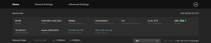
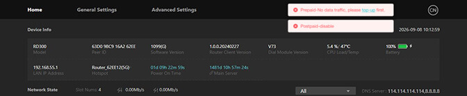
Main Network State dashboard
The Network State Dashboard is the Home Page of the Web Management UI and is divided into 3 key panels:
Device Information:
- Displays core hardware and firmware identification details.
Network State:
- Router Server Connection Status: Displays the active connection state to the TVU Router Server.
- Cellular Modem Network Table (Slots 1, 2, and 3): Displays real-time status for each of the 3 embedded 5G modem slots. Also displays:
- Aggregated Cellular Upload Throughput (Mbps)
- Aggregated Cellular Download Throughput (Mbps)
- Connection Status: Provides real-time visibility into the operational state, health, and throughput of all inbound local connections and outbound multi-path WAN uplinks.
Connected device:
Shows the MAC address and assigned IP address of a device connected to the router.
The Home tab Main Network State UI displays the following information:
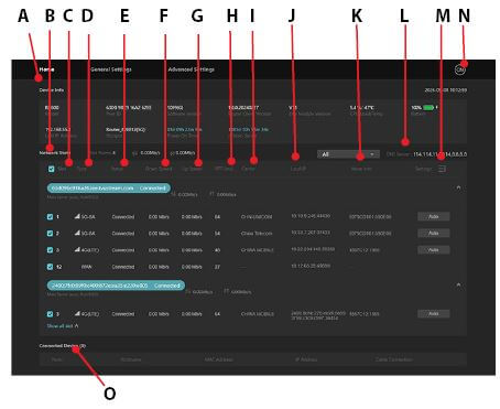
(A) Device info panel: Displays the core hardware and firmware identification details.
(B) Network State panel: Displays the active connection state to the TVU Router Server.
(C) Slot: Displays real-time status across 3 embedded 5G modems (Quectel RM500Q / RM520N-GL). Slots are permanently ordered sequentially: Slot 1, Slot 2, Slot 3.
(D) Type: Displays the mode type e.g 5G SA / 5G NSA / 4G LTE and the wireliess signal strength icon for each connected slot.
(E) Status: Displays the number of currently aggregated links and their Dialing, Connection, and Connected status:
- Dialing: After the SIM card is successfully inserted into the slot and the router is powered on, the router automatically dials. If dialing fails or the router is forced to find a stronger signal, it continues to dial until it’s successful.
- Connecting: Dialing is successful, and the router connects to the server.
- Connected: The server connection is complete.
(F)(G) Down Speed/Up Speed: Displays the total uplink and downlink bitrate speeds:
- Down Speed: Displays real-time down speed in Mbps of the SIM card in the current slot.
- Up Speed: Displays real-time up speed in Mbps of the SIM card in the current slot.
(H) RTT (ms): Displays the real-time delay of the network connection from the router to the gateway.
(I) Carrier: Shows carrier provider name (e.g., China Mobile, Unicom, Telecom, AT&T, Verizon) and the connection standard (5G SA, 5G NSA, or 4G LTE).
(J) Local IP: Displays the server’s IP address assigned to the router’s network connection. If desired, you can uncheck some servers to filter the data.
(K) More info: Displays the base station information for the SIM card connection.
(L) DNS Server: The DNS server is currently in use.
Important notes:
– When the Router has upload and download traffic, the corresponding single-channel network speed displays in the up speed and down speed columns. At the same time, the delay of the link will fluctuate. At the top of the list is the aggregated rate, the sum of all connection rates equal to the sum of all 4G/5G, WiFi, and WAN connections.
– The page will refresh automatically in about 2 seconds. Refresh the browser manually if you need to get the latest information more frequently.
(M) Settings: Sort by server IP or by Slot. Users can select the Network settings for each slot (Auto is the default).
(N) Language selection: Click the icon to change the UI from English to Chinese.
(O) Connected Device panel: Shows the MAC address and assigned IP address of a device connected to the router.
Viewing connected devices
To view the MAC address and assigned IP address of a device connected to the router, refer to the Connected Device panel in “LAN settings.”

Note: Only the device that uses the router DHCP to assign the IP address is displayed.
General settings
The General Settings include the following sub pages:
- Router Server
- WAN IP
- Hotspot
- WiFi
- Intelligent Speed Limit
Configuring Router Server modes
Auto mode vs. Custom mode overview:
- Auto (Default): The router automatically queries the TVU Router Controller (RC) to obtain and connect to the optimal assigned TVU Router Server IP/Domain address (including IPv4 and IPv6 dual-stack endpoints). No manual IP entries are needed.
- Custom: Allows manual configuration of primary and backup TVU Router Server IP addresses or domain names for private, on-premise, or specific regional server deployments.
To configure Router Server modes:
- Connect your computer or laptop to the TVU Nano Router via an Ethernet port or the router’s local Wi-Fi Hotspot.
- Open a web browser and go to the default gateway address: http://192.168.4.1
- Enter your Username and Password to access the Web UI.
- In the top navigation bar, click General Settings.
- Select Router Server from the sub-page tabs.
- Continue with Router Server – Auto mode or “Router Server – Custom mode.”
Router Server – Auto mode
Configuring Auto mode (Recommended):
- Click the Select Server 1 menu and select Auto.
- The manual IP/Domain input fields will be hidden or greyed out.
- Click Apply.
- The router will contact the TVU Router Controller and negotiate server endpoints automatically, populate the fields, and show “Connected” at the bottom of the screen.
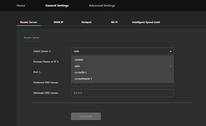
Router Server – Custom mode
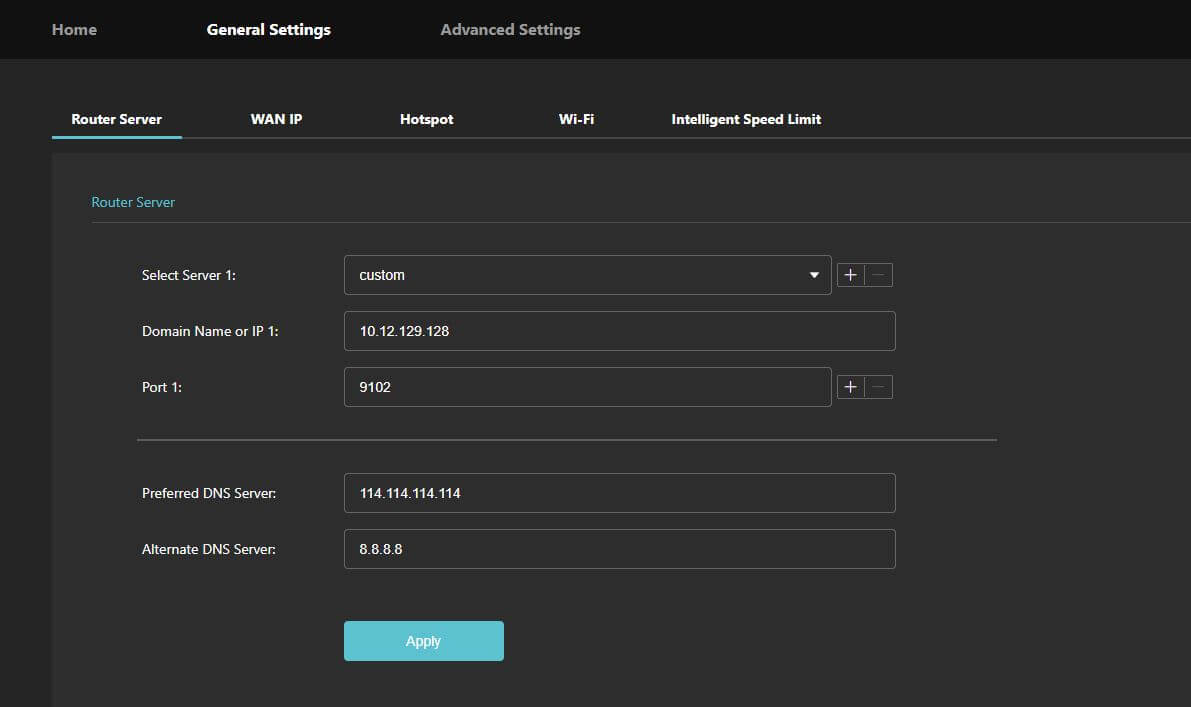
In Custom mode, administrators must manually specify custom server domains or IP addresses (e.g., for private on-premise Router Servers).
- Click the Select Server 1 menu and select Custom.
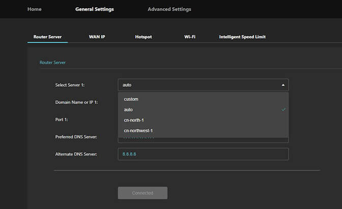
- Enter your custom server details in the enabled input fields:
- Main Server IP / Domain (IP 1): Enter the primary server address (e.g., 192.168.10.50 or myserver.domain.com).
- Backup Server IP / Domain (IP 2): Click the “+” (Optional) to enter a secondary server address for failover redundancy.
- Dual-Stack IP Preference: Select IPv4, IPv6, or IPv4 / IPv6 Dual-Stack from the selection list.
- Click Apply.
- Return to the Home tab.
- Check the Network State Status panel:
- Confirm the connection state displays Connected.
- Verify the active server IP address and latency metrics are populated.
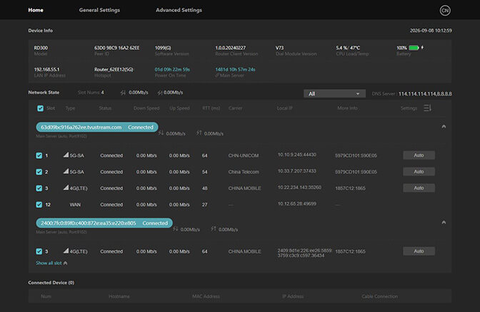
Note: When the server address is connected, it displays “Connected” in the Network State dashboard.
Each active WAN uplink (Cellular Modem Slot 1, 2, 3 / Ethernet WAN / WiFi WAN) that successfully dials and establishes a connection contributes an individual channel to the TVU Router Server. This is accurately reflected in the ISX Bonded Stream Channel Health table on the Network State Dashboard.
WAN IP and LAN settings
The WAN IP settings manage external wired Ethernet connection parameters when plugging the router into an external internet source (such as an office network, venue broadband router, or satellite terminal like Starlink).
Configuring WAN IP Settings
- Connect your computer to the TVU Nano Router via an Ethernet port or the router’s local Wi-Fi Hotspot.
- Open a web browser and navigate to: http://192.168.4.1
- Enter your Username and Password to log in.
- In the top navigation bar, click General Settings.
- Click the WAN IP tab.
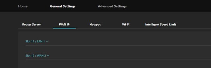
- Move the Port Type slider to WAN and choose an IP Method. There are two options:
- Option A: Auto (DHCP) Mode (Default)
- Select Auto (DHCP).
- The router will automatically acquire an IP address, Subnet Mask, Gateway, and DNS settings from the upstream network.
- Click Save.
- Option B: Static IP Mode
- Select Static IP.
- Enter the network parameters provided by your network administrator:
- IP Address: (e.g., 10.0.1.100)
- Subnet Mask: (e.g., 255.255.255.0)
- Default Gateway: (e.g., 10.0.1.1)
- Primary DNS: (e.g., 8.8.8.8)
- Secondary DNS: (e.g., 8.8.4.4)
- Click Save.
Note: If DNS changes do not take effect properly, domain name resolution will fail, preventing internet access.
- Return to the Home page to verify the WAN IP Connection.
- Check the blue WAN Connection Status widget to confirm the status shows Connected with an active IP address assigned.
Configuring LAN Settings
The LAN Settings control internal network IP routing, local DHCP address assignment pools, connected client visibility, and custom hostname-to-MAC address mapping for downstream devices (laptops, cameras, encoders).
- In the top navigation bar, click Advanced Settings.
- Click the LAN Settings tab.
- In the Router IP Address field, keep the default (192.168.4.1) or enter a custom local gateway IP.
- In the Subnet Mask field, enter the subnet mask (default: 255.255.255.0).
- Scroll to the Connected Devices List on the Home screen.
- Review active wired and wireless clients displaying:
- Hostname
- MAC Address
- Assigned IP Address
- Connection status
Configure Hostnames Mapping (Static IP Binding)
To assign a persistent IP address and custom name to a specific client device (such as a broadcast encoder):
- Scroll to the Hostnames Mapping Table.
- Click Add.
- Fill in the fields:
- Hostname: (e.g., Cam_Encoder_01)
- MAC Address: (e.g., 00:1A:2B:3C:4D:5E)
- Assigned IP: (e.g., 192.168.4.105)
- Click Save.
Tip: Ensure MAC addresses are entered consistently (using all uppercase or all lowercase) to prevent mapping mismatches.
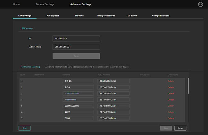
- Click Save to apply all LAN updates.
- If the router IP address was changed, reconnect your browser to the new IP address.
- Connected clients will automatically adopt updated DHCP IP assignments within a few seconds.
Hotspot configuration
External devices can be connected to the router’s hotspot to access an Internet connection.
To configure the TVU Nano Router Hotspot settings:
- Connect your device to the TVU Nano Router via:
- Wired: Ethernet cable into one of the RJ-45 GbE LAN ports.
- Wireless: Connect to the router’s WiFi Hotspot SSID
- Open a web browser and go to: http://192.168.4.1
- Enter your Username and Password to log in.
- In the top navigation bar, click General Settings.
- Click the Hotspot tab.
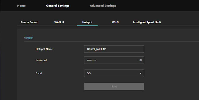
- Configure the Hotspot Name (SSID); Locate the Hotspot Name field.
- Enter your desired WiFi network name (SSID).
Important: Avoid excessively long SSID names as they may affect the Home page layout display.
- In the Password field, enter a strong password for the WiFi Hotspot. The minimum recommended password length is 8 characters.
- Locate the Frequency Band selection option.
- Choose your preferred band:
- 2.4 GHz – Wider range, slower speeds for larger coverage areas.
- 5 GHz – Shorter range, faster speeds for high-bandwidth devices nearby.
- Dual Band – Both 2.4 GHz and 5 GHz active simultaneously for mixed device environments.
- Click Save to apply all Hotspot configuration changes.
- The router will apply the new SSID and password settings within 5–10 seconds.
- To reconnect all wireless client devices (laptops, phones, tablets, encoders), click the WiFi tab to open the WiFi network list.
- Select the new SSID name you configured in Step 7.
- Enter the new password configured in Step 8.
- Confirm the device connects successfully and receives an IP address from the router’s DHCP pool.
- Return to the router Home page to verify Hotspot is active.
- Confirm the Hotspot Status indicator shows Active / Connected.
- Navigate to Advanced Settings > LAN Settings to verify the connected WiFi clients appear in the Connected Devices List with correct IP address assignments.
Tips & Reminders:
- Changing the SSID or Password will disconnect all currently connected wireless clients immediately.
- The 5 GHz band is recommended for HD/4K video production workflows requiring maximum throughput.
- Wi-Fi Hotspot clients share the same bonded uplink as wired LAN clients — apply Intelligent Speed Limits (under General Settings > Intelligent Speed Limit) to manage per-device bandwidth if needed.
- If the Hotspot SSID is not visible on client devices after saving, perform a soft reboot of the router from the Home page.
WiFi configuration
Use the WiFi settings to configure the WiFi Client mode to use external WiFi networks as a WAN connection source.
WiFi WAN allows the TVU Nano Router to connect to an external WiFi network (such as a venue WiFi, mobile hotspot, or office network) and aggregate it as one of its bonded uplink WAN sources alongside the 5G cellular modems and wired Ethernet WAN.
To configure WiFi WAN (Client Mode) on the TVU Nano Router 5G:
- Connect your computer or mobile device to the TVU Nano Router via:
- Wired: Ethernet cable connected to a LAN port
- Wireless: Connect to the router’s local WiFi Hotspot
- Open a web browser and enter the gateway address: http://192.168.4.1
- Enter your Username and Password to log in.
- In the top main navigation bar, click General Settings.
- Click the WiFi tab.
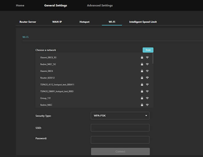
- Click the Scan button to discover available local WiFi networks.
- Review the list of detected networks showing:
- SSID (Network Name)
- Signal Strength (%)
- Security Type (e.g., WPA2-PSK, WPA3)
- Frequency Band (2.4 GHz / 5 GHz)
- Select your target external WiFi network and click Connect.
- In the Selected SSID Password field, enter the security key for the target network.
- Click Apply and Connect.
- Allow 10–15 seconds for the router to authenticate, negotiate an IP address, and establish the link.
- Return to the Home page and locate the Network State list.
- Confirm that the WIFI slot appears under your Main Server with Status: Connected, its checkbox selected, and a Local IP assigned by the upstream network.
Tips & Reminders:
- WiFi WAN and local WiFi Hotspot operate independently. Enabling WiFi WAN does not disable your local Hotspot.
- For broadcast/live streaming workflows, connect to 5 GHz WiFi networks whenever possible for higher bandwidth and lower latency.
- Captive portal networks (networks requiring web page click-through logins, like hotel WiFi) must be authenticated via a connected client browser or bypassed.
Intelligent Speed Limit
The Intelligent Speed Limit feature enables you to control per-client and global download/upload rate limits across connected LAN and WiFi devices; set the device’s maximum upload and download speed, priority of a single card, maximum upload, and download speed.
To configure the Intelligent Speed limit settings:
- Connect your device to the TVU Nano Router via:
- Wired: Ethernet cable into one of the RJ-45 GbE LAN ports.
- Wireless: Connect to the router’s WiFi Hotspot SSID.
- Open a web browser and go to: http://192.168.4.1
- Enter your Username and Password to log in.
- In the top navigation bar, click General Settings.
- Click the Intelligent Speed Limit tab.
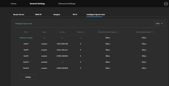
- Click the Setting button.
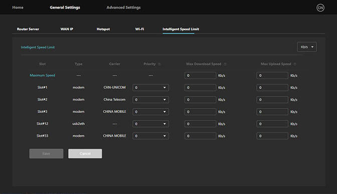
- Set Global Bandwidth Limits (Optional). Select a speed from the dropdown menu. Before assigning per-device priorities, set the overall maximum bandwidth available across all connected devices:
- Global Max Upload speed (e.g. 100 Mbps)
- Global Max Download speed (e.g. 250 Mbps)
Note: Individual device limits and priorities cannot exceed the Global Max values set here.
- Locate the device you want to prioritize by Hostname or IP Address.
- Assign a Priority Level from the dropdown:
- High (P1): Receives bandwidth first before all other devices. Recommended for Live video encoders, broadcast cameras.
- Normal (P2): Standard allocation — receives bandwidth after High priority devices. Recommended for Laptops, production computers.
- Low (P3): Receives remaining bandwidth only after P1 and P2 devices are served. Recommended for phones and non-critical devices.
- Set the Upload and Download speed caps for that device:
- Max Upload rate (Upload cap for this device e.g. 20 Mbps)
- Max Download (Download cap for this device e.g. 50 Mbps)
- Repeat for all devices requiring priority assignments.
- Click Save at the bottom of the page.
Note: Speed limit rules take effect immediately — no reboot required.
- Verify the priority rules are working:
- On a High Priority (P1) device (e.g., Live Encoder), run a speed test to confirm it receives its full allocated bandwidth.
- On a Low Priority (P3) device (e.g., Guest Phone), run a speed test and confirm its throughput is capped below the P1 and P2 devices.
- On the client device, run a speed test using:
- A browser-based tool such as speedtest.net.
- Command line: speedtest-cli
- Return to the Setting screen in the Web UI to confirm the rules are listed correctly.
Tips & Reminders:
- Always assign High (P1) priority to live broadcast encoders and video cameras to ensure uninterrupted transmission.
- If a device does not appear in the client list, ensure it is actively connected to the router before assigning priority rules.
- To remove a priority or speed cap, set the values to 0 (unlimited) and priority back to Normal (P2).
- Priority rules apply equally to both wired LAN and WiFi Hotspot connected clients.
- Per-client upload/download limits cannot exceed the Global Max values configured at the top of the page.
Note: The default setting is unlimited and displays as “0”.
Advanced Settings
The Advanced Settings menu contains six core sub-pages designed for network control, modem management, and system security.
- LAN Settings
- P2P Support
- Modems
- Transparent Mode
- L2-Switch
- Change Password
LAN settings
LAN Settings control internal network addressing, local DHCP services, device mapping, and connected client visibility.
To set the IP address and mask of the router, complete the following steps:
- Connect a device (laptop, desktop, or tablet) to the TVU Nano Router via:
- Wired: Plug an Ethernet cable into one of the RJ-45 GbE LAN ports.
- Wireless: Connect to the router’s WiFi Hotspot SSID.
- Open a web browser and navigate to the router’s default gateway IP address (http://192.168.4.1) of the aggregation router.
- Enter your Username and Password to log into the Web Management Console.
- Click Advanced Settings and select the LAN Settings tab.
- To configure the Router LAN IP Address, locate the Router IP Address field.
- Enter the desired local gateway IP address (default: 192.168.4.1).
- Enter the corresponding Subnet Mask (default: 255.255.255.0).
- View connected devices. Scroll down to the Connected Devices List section on the Home screen.
- Review the real-time list of connected client devices displaying:
- Hostname
- MAC Address
- Assigned IP Address
- Connection Status
- Configure Hostnames Mapping (Optional). To assign a custom hostname to a specific device:
- Scroll to the Hostnames Mapping Table.
- Click Add New Mapping.
- Enter the following details:
- Hostname: Custom name for the device (e.g., Cam_Encoder_01)
- MAC Address: The device’s MAC address (e.g., 00:1A:2B:3C:4D:5E)
- Assigned IP: The static IP address to reserve for the device (e.g., 192.168.4.105)
Important: Ensure the MAC address is entered consistently in either all uppercase or all lowercase to avoid mapping failures.
- Click Save to apply all LAN configuration changes.
Note: Allow 5–10 seconds for the router to update DHCP and LAN parameters.
- Reconnect any affected client devices to receive updated IP assignments.
- To verify the configuration on a connected client device, run ipconfig (Windows) or ifconfig / ip addr (Linux/Mac) to confirm the assigned IP is within the configured DHCP pool range.
- Ping the router gateway (192.168.4.1) to verify LAN connectivity: Enter ping 192.168.4.1
- Return to the Connected Devices List in the Web UI to confirm the device appears with the correct hostname and IP address.
- For external devices that are connected to the router using a network cable, the IP allocation method uses DHCP by default. As the IP address and mask of the router change, the address assigned to the devices will also change.
P2P settings
The P2P function is used in typical applications to interconnect between a device connected to the router and the device under the aggregation gateway server. To learn more about enabling and using the P2P function, refer to “Typical P2P deployment scenarios.”
Modem configuration
The Modems configuration window Provides control and diagnostic options for the three embedded 5G modem slots (Quectel RM500Q / RM520N-GL).
General mobile phone SIM cards and IoT cards have default configurations, which need to be modified under special circumstances such as private APNs, roaming overrides, IoT-specific credentials, or enterprise fixed-IP SIM configurations.
To set the parameters of the mobile SIM card for internet access:
To configure 5G SA (Standalone) vs. NSA (Non-Standalone) mode and modem band preferences:
- Open a web browser on a device connected to the router via LAN or WiFi.
- Log into the TVU Nano Router Web Management UI.
- Click Advanced Settings and select the Modems tab.
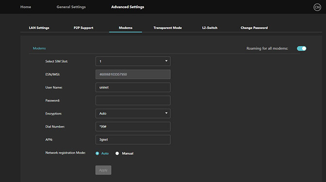
- In the Select SIM Slot dropdown menu, choose the modem slot you want to configure:
- Slot 1 (e.g., Quectel RM500Q / RM520N-GL)
- Slot 2
- Slot 3
- Check the current status indicator to verify the inserted SIM card and carrier details.
- To Switch to the Manual / Network Mode Selection, under Mode Selection, toggle the mode to Manual if required to override automatic network locking.
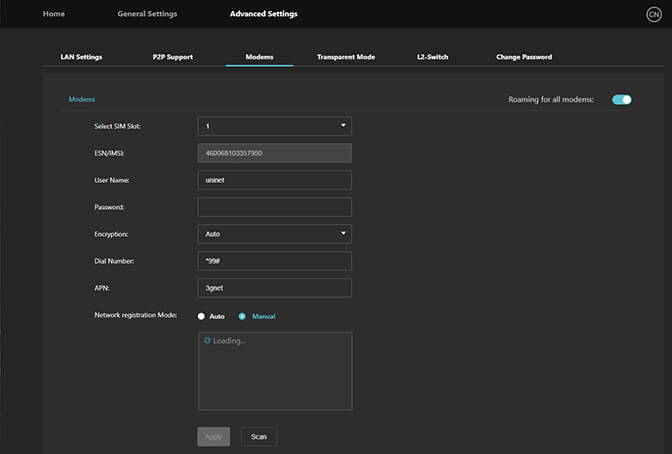
- Locate the Network Registration Mode / Network Lock selection dropdown.
- Choose your desired 5G operating mode from the dropdown menu:
- 5G SA (Standalone): Forces the modem to connect exclusively to native 5G Core (5GC) networks without using a 4G LTE anchor band (ideal for low latency and dedicated 5G slicing where supported by the carrier).
- 5G NSA (Non-Standalone): Configures the modem to operate using 5G NR dual connectivity with a 4G LTE anchor band (ideal for wider coverage and standard 5G carrier networks).
- 5G SA / NSA Auto (Default): Automatically negotiates between 5G SA, 5G NSA, and 4G LTE based on real-time signal strength and carrier availability.
- 4G LTE Only: Restricts the modem to 4G LTE networks only.
- Click Save to update the settings for the selected slot.
- If you want the same 5G SA/NSA mode applied across all 3 embedded modems, click Apply All Slots.
- Allow 10–30 seconds for the modem to re-initialize and complete network registration.
Transparent Mode
Transparent Mode (Bridge / Passthrough Mode) bypasses the router’s internal NAT (Network Address Translation). It passes the aggregated WAN uplink directly through to a downstream device (such as a hardware firewall, enterprise router, or broadcast encoder), allowing that downstream device to acquire an IP directly from the bonded uplink network.
The Transparent Mode feature lets you to transmit to a destination IP and Source IP transparently. When this feature is enabled, the IPs display as “0.0.0.0/0”. This function is disabled by default.
To enable and configure Transparent Mode:
- Connect your computer to the TVU Nano Router via:
- Ethernet: Plug a LAN cable into one of the router’s GbE LAN ports.
- WiFi: Connect to the router’s Wi-Fi Hotspot SSID (TVU_Nano_5G_RD300).
- Open a web browser and navigate to: http://192.168.4.1
- Enter your Username and Password to log in.
- In the top navigation bar, click the Advanced Settings dropdown menu.
- Click the Transparent Mode tab.
- Locate the Transparent Mode Status toggle switch at the top of the page.
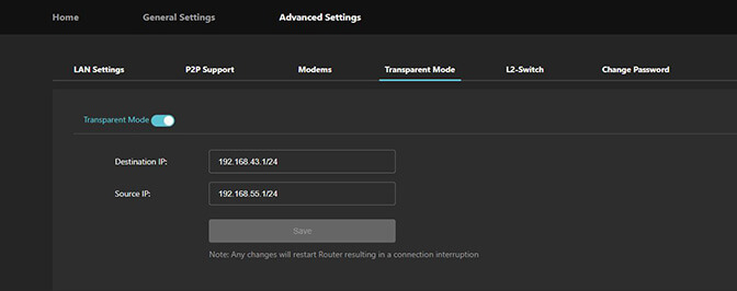
- Click the switch to set it to ON / Enabled.
- Enter the Destination IP and Source IP. When using multiple addresses, they must be separated with a comma “,”.
Three types of address ranges are supported, including P2P settings. Supported address ranges are:
- Address segment: Defines a continuous range of IP addresses specified with a start and end address separated by a hyphen (-). For example:
- 192.168.4.1-192.168.4.32
- Mask form (CIDR): Defines a subnet block using standard CIDR prefix notation (IP/prefix). For example: 192.168.3.0/27
- Single address: Defines a discrete host IP address (equivalent to a /32 host route). For example:
- 192.168.100.100
- Click Save. Saving restarts the router and interrupts all active connections.
- To disable Transparent Mode, set the switch to OFF and click Save again. Moving the switch changes nothing until you save.
Configuration Notes:
- Validation: All three formats must use valid IPv4 addresses and must not overlap with active WAN interface subnets (e.g., cellular modems, WiFi WAN).
- P2P / Transparent Routing: These formats allow flexible routing rules—whether you want to pass through a single specific device, a small contiguous pool, or an entire subnet across the bonded connection.
Typical P2P deployment scenarios
This section describes how the P2P function configures interconnection between devices and routers using the same aggregation gateway.
The IP Range field under Advanced Settings › P2P Support takes only three forms, and several can be separated by commas:
- single host: 192.168.4.10
- CIDR: 192.168.4.0/24
- range: 192.168.4.1-192.168.4.32
The following shows two typical P2P deployment scenario examples:
Scenario 1: P2P between a device behind the Router and a device behind the aggregation gateway server.
Subnet Constraint (Important):
- Non-Overlapping Subnets: The local LAN subnet on the TVU Router side and the local LAN subnet on the TVU Router Server side must not overlap or be identical.
- Example conflict: If the Router LAN is configured as 192.168.1.0/24, the Router Server LAN cannot also use 192.168.1.0/24.
- Virtual/Tunnel Subnet Isolation: Neither site’s local LAN subnet may overlap with the virtual P2P tunnel subnet / IP range assigned for the TVU point-to-point link.
- Routing Requirement: Each endpoint network must use a unique, distinct IP subnet (e.g., Router LAN: 192.168.10.0/24, Router Server LAN: 192.168.20.0/24, Virtual P2P Tunnel: 10.x.x.x/24) to prevent IP routing collisions across the tunnel.
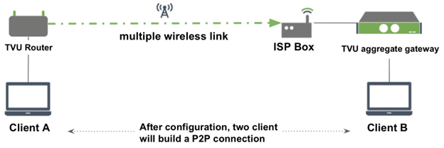
Client A configures the Router:
- Router LAN: e.g.,192.168.10.0/24
- Turn P2P Support on, enter the IP Range, and click Save. Saving restarts the router and interrupts all active connections.
Scenario 2: P2P interconnection between devices connected to 2 routers under the same aggregation gateway server.
Strict Subnet Separation (No Overlap):
- Router A Local LAN Subnet, Router B Local LAN Subnet, and the Gateway Virtual Tunnel Subnet must all be distinct and non-overlapping.
- Example Plan:
- Router A LAN: 192.168.10.0/24 (Router IP: 192.168.10.1)
- Router B LAN: 192.168.20.0/24 (Router IP: 192.168.20.1)
- Aggregation Gateway Subnet / Tunnel: 10.100.0.0/24
- Example Plan:
DHCP / Gateway Settings on Client Devices:
- Client devices connected behind each router must use their respective router as their default gateway so packets targeting the other router’s subnet are forwarded into the tunnel.
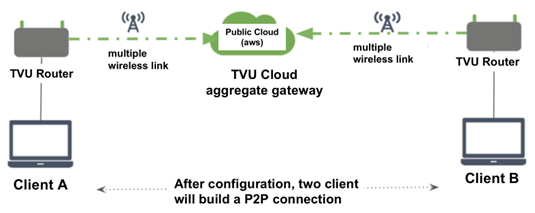
Client A configures the Router:
- Router A LAN: e.g., 192.168.10.0/24 (Router IP: 192.168.10.1)
- Turn P2P Support on, enter the IP Range, and click Save. Saving restarts the router and interrupts all active connections.
Client B configures the Router:
- Router B LAN: e.g., 192.168.20.0/24 (Router IP: 192.168.20.1)
- Turn P2P Support on, enter the IP Range, and click Save. Saving restarts the router and interrupts all active connections.
P2P Configuration interface
P2P Support establishes a direct, encrypted Point-to-Point tunnel between two TVU Router units (or between a TVU Router and a designated remote server/peer node) across bonded 5G/4G/WAN uplinks, allowing low-latency LAN-to-LAN communication.
To configure P2P Support:
- Open a web browser and navigate to http://192.168.4.1.
- Log in with your credentials.
- In the top navigation bar, click Advanced Settings and select P2P Support.
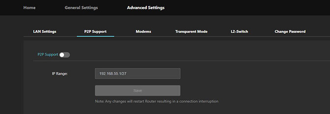
- Enable the P2P Feature. Set the P2P Support toggle switch to ON.
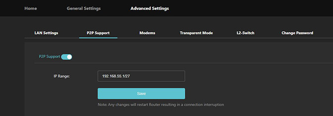
Note: The IPs of the devices at both ends cannot be exactly the same. Enabling/disabling/modifying P2P settings will interrupt the network for about 2 seconds.
- In IP Range, enter the subnets on this router that should be reachable over the tunnel, using the formats listed above. Separate multiple entries with commas.
- Click Save. Saving restarts the router and interrupts all active connections.
NAT/No NAT server switching
NAT (Network Address Translation)
What it does: The device (router, transceiver, or gateway) sits between the local network (LAN) and the external/bonded network (WAN), translating private local IP addresses (e.g., 192.168.x.x or 10.x.x.x) into an external IP address.
No NAT (Bridged / Direct Routing / Pass-Through)
What it does: Network Address Translation is disabled. Network packets pass through the device with their original source and destination IP addresses intact.
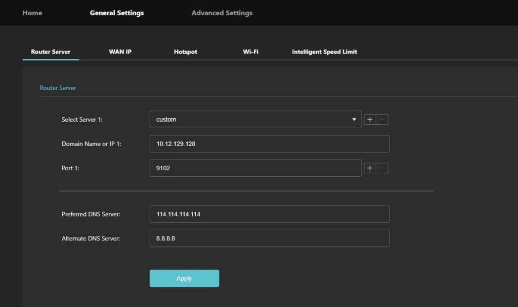
NAT is also not a concept in the router’s web UI. The distinction is the auto and custom options in the Select Server 1 dropdown.
Auto / Custom Router Server
The Nano Router connects to a Router Server, chosen under General Settings › Router Server in Select Server 1:
- auto: TVU’s cloud Router Servers. The system selects and allocates one for you, and the address, port, and DNS fields are filled in automatically. The us-east and us-west pin the connection to a specific region.
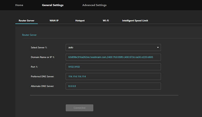
- custom: a Router Server deployed on your own premises. Enter its Domain Name or IP, Port, and DNS servers, then click Apply.
Cloud Router Servers are provisioned by TVU. An on-premise Router Server is installed and configured together with the TVU support team.
Horizontal Expansion and Remote Backup server support
When Auto is selected on the General Settings > Router Server screen, the system operates in dynamic automatic discovery and routing mode rather than routing traffic to a manually specified static server.
The dropdown has four options, covering two kinds of Router Server:
- auto and the region options (us-east / us-west): TVU’s cloud Router Servers. auto lets the system allocate one; a region option pins the connection there. The Domain / Port / DNS fields are filled in and greyed out, and the button reads Connected.
- custom: a Router Server deployed on the customer’s own premises. The four fields become editable, and the button changes to Apply.
Horizontal Expansion support
- Multi-Unit Clustering & Scaling: The RD300 architecture allows multiple hardware units to be deployed and operate in tandem (horizontal scaling) rather than relying solely on vertical hardware upgrades.
- Capacity & Throughput Expansion: By adding additional RD300 units into a deployment, you can horizontally expand the number of concurrent bonded streams, input/output channels, and aggregate bandwidth across your network infrastructure.
- Centralized Management: When managed through TVU Command Center or centralized routing (TVU Grid / ISX ecosystem), multiple RD300 units can be pooled and assigned dynamic workloads across the cluster.
Remote Backup Server Support
- Redundant Destination Routing: The RD300 supports pairing with a designated remote secondary/backup server (or secondary receiver destination).
- Automatic Failover & High Availability (HA): In the event that the primary server/link experiences degradation, network disconnection, or hardware downtime, transmission streams can fail over to the configured remote backup server with minimal interruption.
- Disaster Recovery / Off-Site Redundancy: Remote backup configurations allow the secondary server to reside in an entirely different physical facility, data center, or cloud region to meet enterprise disaster recovery (DR) requirements.
If the gateway device serving the router fails, it will automatically switch to other available aggregation gateways to ensure the uninterrupted operation of aggregation services.
Turning the Nano Off
After use, complete the following steps to turn the Nano Off:
- To turn the nano router off when the nano is running in normal mode, press and hold the power button for 5 seconds, then release the button. The device shuts down normally when the indicator light is no longer illuminated.
- The device may experience an unknown status when running, such as being unable to view the Web interface or the battery having too much capacity. If this occurs, press and hold the power button for 10 seconds to shut down the nano router immediately.
L2-Switch mode
Layer-2 Bridging: Configures physical LAN ports into direct L2 switch mode, passing broadcast and multicast packets across connected segments.
Subnet & Protocol Pass-Through: Essential for broadcast workflows requiring direct local network discovery, NDI, or custom IP protocol passthrough across remote sites.
To configure LAN ports into direct L2-switch mode:
- Open a web browser and navigate to http://192.168.4.1.
- Log in with your administrator credentials.
- Click Advanced Settings and select the L2-Switch tab.
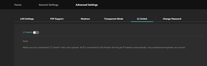
- To Enable L2-Switch Mode, set the L2-Switch Status toggle switch to ON / Enable. A Caution message appears.
- If you are confident in your selection, click Turn on, otherwise click Cancel.
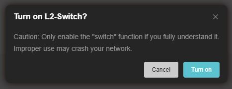
- Select Switch Ports & VLAN Settings:
- Port Member Selection: Check the physical Ethernet ports (e.g., LAN 1, LAN 2, WAN) to include in the Layer 2 switch group.
- VLAN Tagging (Optional): Enable VLAN tagging and specify the VLAN ID (1–4094) if connecting to a tagged trunk port on an upstream/downstream managed switch.
- Spanning Tree / Loop Detection: Enable Loop Protection if connected to redundant external switches.
- To configure Management IP, select whether the switch interface maintains a local management IP via DHCP or Static IP for accessing the Web UI (192.168.4.1).
- Click Save or Apply.
- To verify Switching:
- Plug network cables into the assigned switch ports.
- Verify that downstream devices on different ports can ping each other directly across the Layer 2 network.
Change password
To change administrative authentication access to the TVU Nano Router Web User Interface:
- Open a web browser and navigate to http://192.168.4.1.
- Log in with your administrator credentials.
- Click Advanced Settings and select Change Password.
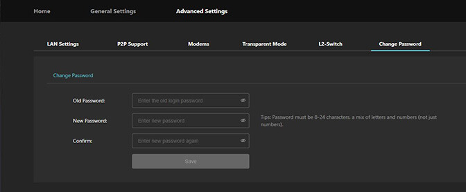
- Enter the old password, New password, and confirm the New Password.
© Copyright 2026 TVU Networks Corporation. All rights reserved in all media.
Document Part Number: TVU Nano Router 5G Setup and User Guide Rev E EN 09-2026
Related tips
