Contents
- Introduction and Pack preparation
- Before you begin
- Charging the internal battery
- Software setup, configuration, and going live
- TVU transmitter Live status screen descriptions
- Selecting a receiver and going Live
- Starting and stopping the transmission
- TVU One Settings menu
- Selecting a Receiver
- Selecting an encoder
- Delay management
- VoIP & IFB
- Slot monitoring
- About
- Language selection
- Hotspot
- Router
- Switch
- Stream
- Self-Check
- Progressive Download
- Return Video Feedback (RVF)
- Upload
- Transfer
- Speedtest
- USB remote control PTT button operations
- VoIP call operations
- SCTE Insertion
- Preroll parameters and default values
- SCTE Pack controls
- Tally status display
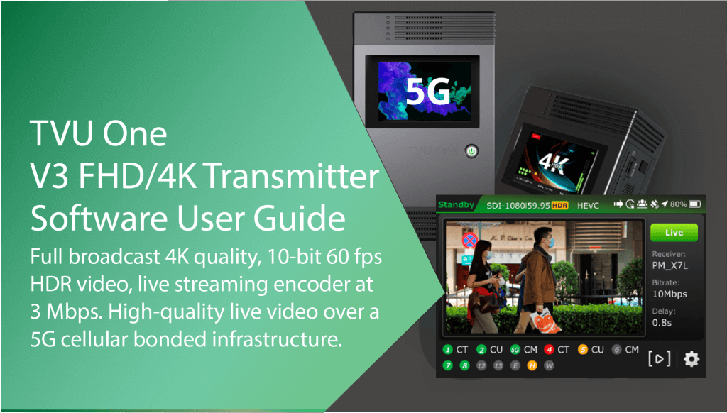
TVU One TM1000v3 FHD and 4K Software Quick Start User Guide
Introduction and Pack preparation
Note: The contents and features in this software user guide is compatible with TM1000 V3 FHD / V3 4K v7.3 and higher (Linux R) and v6.5 and higher (Windows R).
TVU One 4K delivers high-definition picture quality with 0.3-second latency at 3 Mbps. The TVU One FHD and 4K transmitters use the H.265/HEVC or H.264 encoding and compression standard to deliver greater data efficiency and transmission stability.
The H.265 hardware encoding chip delivers full broadcast quality in 4K, 10-bit true 60 fps video at as low as 3 Mbps with proven patented Inverse StatMux Plus technology, ISX.
ISX is the ultimate transmission algorithm. TVU One 4K uses less data and combats packet loss to achieve transmissions with virtually zero latency, down to 0.3 seconds, even in a moving vehicle or when going live in 4K. The TVU One FHD transmitter can also transmit live 1080p-60 at as low as 800 Kbps. ISX offers better utilization of available bandwidth in congested/low-signal areas and has extremely low latency as low as 0.3 seconds on cellular.
Both TVU One transmitter models simultaneously aggregate up to 12 data connections and can obtain bandwidth from anywhere: cellular 3G/4G/5G, WiFi, Ethernet, or satellite.
The TVU One 4K and FHD models have 100% more battery life than their predecessors. The TVU One FHD can communicate without latency using IFB and bidirectional VoIP between the studio and the field operator.
Real-time dual encoding allows you to go live under any network conditions by simultaneously recording a full HD copy of your video for later download.
Before you begin
Before using your TVU One transmitter, refer to the latest TVU One FHD and 4K Hardware Quick Start User Guide to set up the hardware and identify the devices you intend to use with the unit, including cameras, cables, power sources, modems, TVU services, and unit accessories.
TVU One software builds (v6.8.2, v7.0, and higher) support the RVF adapter and can be controlled using the LCD touchscreen. It includes an RVF option to support viewing return video feeds from an iPhone or iPad. Refer to the TVU One data sheet for more features.
Builds prior to v8.2 featured two LCD console interfaces to choose from.
If you prefer using the improved TVU One console featured in this user guide, contact tvusupport@tvunetworks.com to upgrade your Pack’s software version.
About this guide
This software user guide provides information about performing the basic configuration and operating the TVU One.
Charging the internal battery
Note: The battery will charge faster if the TVU One unit is powered off.
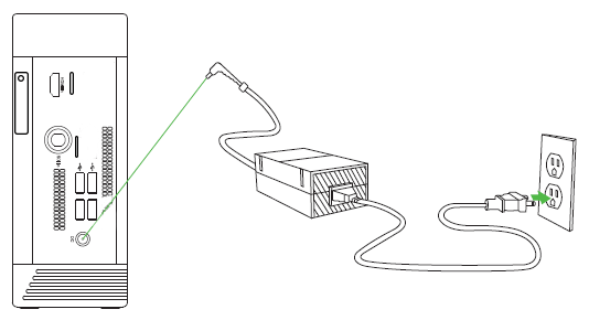
The TVU One comes with an AC adapter for charging. Connect the AC adapter as shown to charge the TVU One.
Power button and battery icon status when charging
The TVU One displays the following power button and battery icon status when the AC adapter is properly connected and the battery is charging:
- When the unit is powered on and charging, the power button displays a steady green light. The battery icon displays the percentage of charge left and indicates charging movement in green.
- When the unit is on, the battery icon turns red and displays the percentage of charge left when a charge is required.
- When the unit is powered on, the power light flashes red and green during a forced shutdown.
- When the unit is powered off and charging, the power light displays a flashing red light.
- When the unit is fully charged and on, the power light displays a steady green light and the LCD battery symbol displays 100%.
- The power light is off when the battery is not charged or connected to the unit.
- When fully charged and the power is off, the power light displays a steady red light.
Software setup, configuration, and going live
TVU LCD touchscreen interface
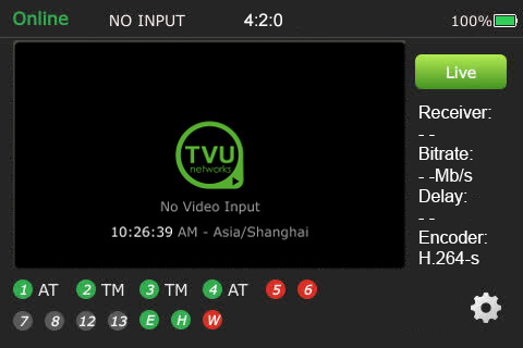
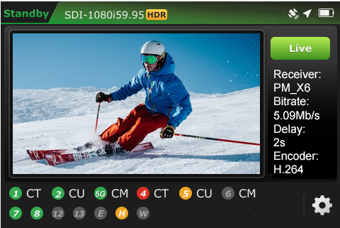
The transmitter’s new LCD touchscreen interface allows transmission control in the field. When the transmitter is first turned on and SDI is connected, the user sees the status display screen.
- The latest TVU One touchscreen interface will display.
- Tap the touchscreen configuration (gear icon). The Swipe to unlock screen will display. Tap and swipe to the right.
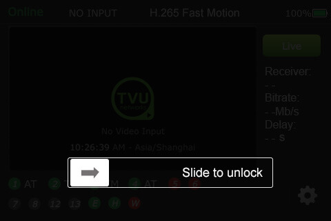
- The latest TVU One touchscreen interface will display unlocked.
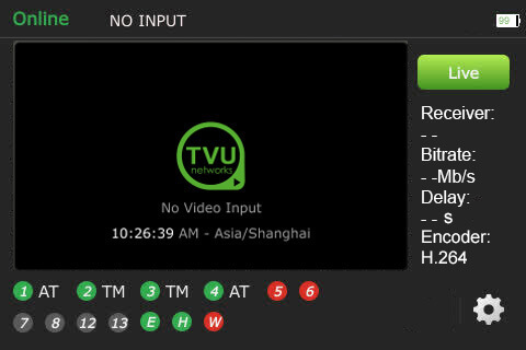
TVU transmitter Live status screen descriptions
When SDI is connected, transmission control in the field is allowed.

TVU One transmitter Live status screen descriptions
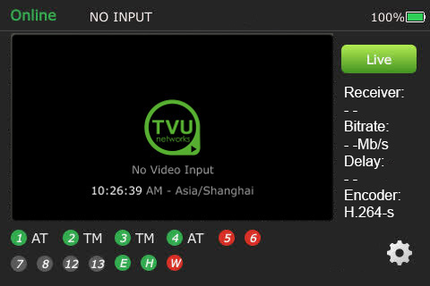
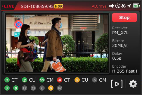
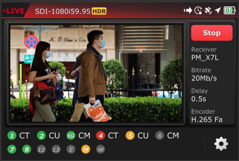
(A) Transmission Status: The transmission status monitor displays the TVU Pack’s current transmission status. If the LCD screen displays “LIVE,” it indicates the transmission is Live. If a camera or input source is not connected to the TVU One transmitter, the LCD screen will display “Online” (Standby) or Preview mode.
(B) Display LCD: “No Video Input” is displayed on the LCD screen when the transmitter is not connected to a transmission feed.
(C) Data Card Status Monitor:
Displays the current number and status of all data cards connected to the TVU One. The status of data cards connected to the Pack will appear as green, red, orange, or black. The green status indicates that the data card is connected. The orange status indicates that the data card is attempting to dial. The red status indicates that the data card is not connected. The black status indicates the absence of a card.
(D) Ethernet Connection: Displays the status of the Ethernet connection.
(E) Hotspot Connection: Displays the status of the hotspot connection.
(F) WiFi Connection: Displays the status of the WiFi connection.
(G) Latency (Delay) Status: Displays the current latency of the transmission.
(H) Bitrate Status: Displays the current Bitrate (B/R).
(I) Receiver Name: Shows the receiver name to which the unit is transmitting.
(J) Battery Status: Indicates the battery’s status.
Going Live
To go live using the receiver with which you last went live:
- Tap the Live button on the initial status screen to start the live transmission.
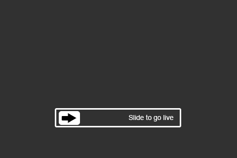
- The TVU One unit will prompt you to slide the ‘Slide to go live’ button from left to right.
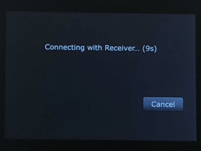
- Once the button is engaged, the TVU One countdown displays before the live transmission begins using the last receiver with which you most recently went Live.
Selecting a receiver and going Live
All configuration options and settings are now accessible using the gear-shaped icon in the bottom right of the LCD touchscreen.
To select a new receiver and go live:
- Tap the Gear icon to open the Main menu.
- The new Main menu will display. The new menu allows users to reorder, remove, and add menu options to customize the menu order based on user habits.
Note: The Settings and Hotspot buttons can not be removed.
- Tap Settings.
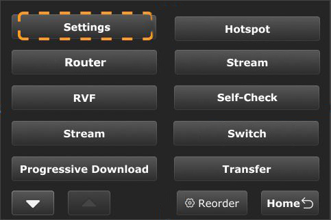
Note: To return to the previous screen, tap the Home button.
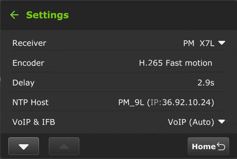
- The Settings menu will display. Tap the Receiver menu.
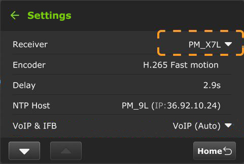
- Select the receiver you want to go live with from the drop-down menu, tap OK, then tap the Go Live button.
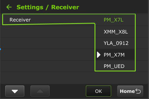
Note: When starting a live transmission from this menu, you will not be prompted to slide a button. The transmission will begin with a countdown.
- If you only want to select a receiver but do not want to go Live, tap the Home button at the bottom-right corner of the LCD touchscreen.

Starting and stopping the transmission
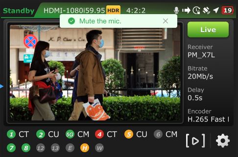
When the SDI camera source is connected, the “Standby” screen will display until you take the transmission live.
To take the transmission live:
- Tap the green Live button.
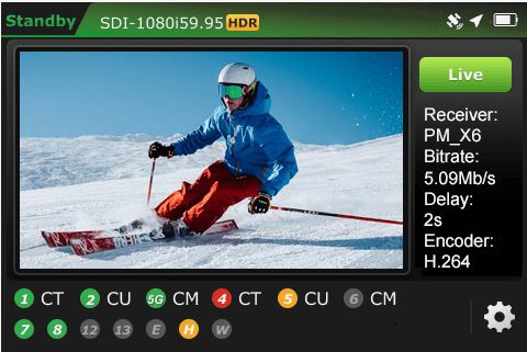
- The transmitter will display a prompt for you to slide the ‘Slide to go live’ button from left to right.
- When a transmission is live with a receiver, a red Stop button will be displayed.
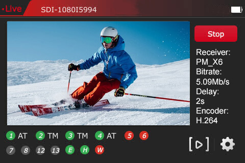
To stop the live transmission:
- Tap the Stop button.
- The LCD will return to the “Standby” mode when the live transmission is stopped.
TVU One Settings menu
This section describes how to locate the TVU One pack Settings menu items and configure them using the LCD touchscreen.
- Tap the Gear icon at the bottom right of the touchscreen.
- The Main menu appears. Tap Settings.
Selecting a Receiver
- Tap the Gear icon at the bottom right of the touchscreen to open the Main menu.
- The Main menu appears. Tap Settings.
- The Settings menu will display. Tap the Receiver menu.
Note: All of the selections in the menu are clickable except for the Story selection.
- Select the receiver you want to go live with from the drop-down menu and tap OK.
Selecting an encoder option
The TVU One model FHD and 4K support on-board H.265/HEVC or H.264 encoding.
To select an encoding option:
- Tap the Gear icon at the bottom right of the touchscreen to open the Main menu.
- The Main menu appears. Tap Settings.
- Tap Encoder.
- Select an Encoding and Bandwidth option:
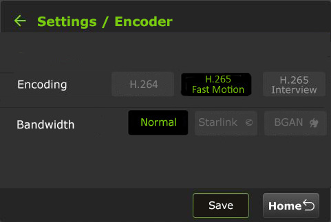
Note: Your selection will highlight green. The pack must be in live mode before you can change selections.
- H.264 Normal
- H.265 Fast Motion
- H.265 Interview
- Bandwidth: Normal, Starlink, or BGAN mode
BGAN Notes:
- BGAN mode is designed to handle the specific latency conditions of a BGAN satellite connection.
- Use HDR Full Asymmetric mode (Full HDR Upload, 64 kbps download).
- Use an Ethernet connection between the BGAN terminal and TVU One.
- Set the TVU One to CBR 500 kbps @ 3 sec.
- Set the TVU One Encoder mode on the touchscreen to HEVC Interview Mode and Bandwidth to BGAN Mode.
- To save your selection, tap Save.
- Tap the back arrow to return to the main menu. Tap Home to return to the initial status screen.
Delay management
To manage the second and sub-second Latency settings:
- Tap the Settings gear icon at the bottom of the LCD touchscreen.
- The Main menu appears. Tap Settings.
Note: To Exit this menu, tap the Home button.
- Tap Delay.
- Tap a box and use the up and down arrows to set the delay.
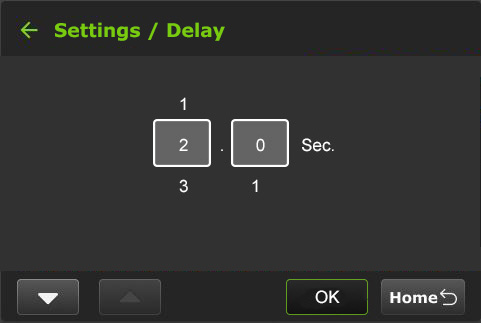
- Tap OK to confirm your settings.
- Tap the back arrow to return to the main menu. Tap Home to return to the initial status screen.
NTP Host
Users can view the NTP host status on the touchscreen display.
- Tap the Gear icon at the bottom of the LCD touchscreen.
- The Main menu appears. Tap Settings.
- The NTP Host IP address is displayed. The address is configured in the Advanced settings Web UI panel.
VoIP & IFB
To configure VoIP and IFB settings:
- Tap the Gear icon at the bottom of the LCD touchscreen.
- The Main menu appears. Tap Settings.
- Tap VoIP & IFB.
- Select a VoIP or IFB configuration.
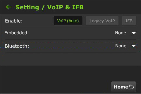
- Tap the back arrow to return to the main menu. Tap Home to return to the initial status screen.
Data card monitoring (Slot)
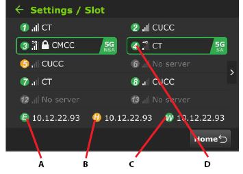
To monitor detailed encoder information along with Ethernet, hotspot, and WiFi connections:
- Tap the Gear icon at the bottom of the LCD touchscreen.
- The Main menu appears. Tap Settings.
- Scroll down the menu and tap Slot.
- The data cards and their status display along with Ethernet, Hotspot, and WiFi indicators:
(A) Data cards
(B) Ethernet
(C) Hotspot
(D) WiFi connection
- Tap the back arrow to return to the main menu. Tap Home to return to the initial status screen.
Slot speed
A user can view the real-time speed of each slot and change the Network settings.
To view a slot speed:
- Tap the “>” to view its real-time speed setting.

- The real-time speeds of the connected slots are displayed.
- To return to the data card view, tap the “<” icon.
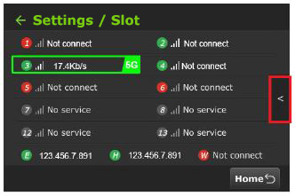
- To open the Network Setting menu, tap a slot.
- The Network Setting pop-up will display. Users can choose to lock in to a different speed if desired and Save the change.
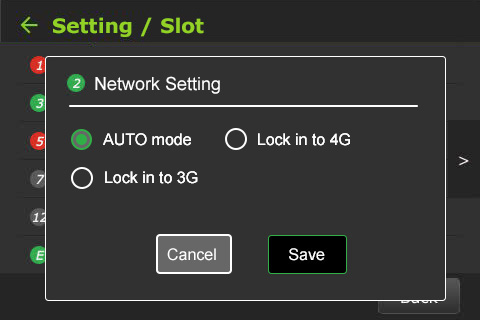
- Tap Cancel to return to the Slot monitoring screen without changing the Network Setting.
- Tap the back Arrow to return to the Slot monitoring screen without changing the Network Setting,
- To return to the Setting screen, tap the back Arrow again.
Story
Note: All of the selections in the main menu are selectable except for the Story selection.
TVU One transmitter information – About
The About screen provides information on the model number, Peer ID, software version, App version, and region.
To access the About screen:
- Tap the Gear icon at the bottom of the LCD touchscreen.
- The Main menu appears. Tap Settings.
- Tap the “∇” button to scroll down to the bottom of the Settings menu and tap About.
- The TVU One’s About window displays. The APP information will display ISX.
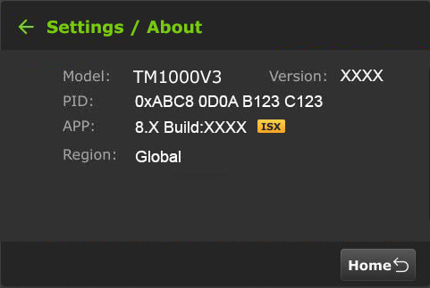
- Tap the back arrow to return to the main menu. Tap Home to return to the initial status screen.
Language selection
The Language screen allows the user to choose English or Chinese.
To select a language:
- Tap the Gear icon at the bottom of the LCD touchscreen to open the Main menu.
- The Main menu appears. Tap Settings.
- Tap the “∇” button to scroll down to the bottom of the Settings menu and tap Language.
- Select your Language option. The default is English.
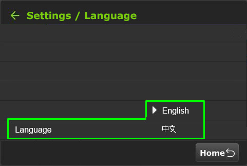
- Tap the back arrow to return to the main menu. Tap Home to return to the initial status screen.
WiFi
The pack will automatically attempt to reconnect if the current WiFi connection disconnects.
When multiple WiFi adapters are connected, you can scan available slots for WiFi adapters and configure the WiFi login information by scanning the Configuration QR code and using the TVU One WiFi setup and configuration page. For detailed information, refer to General > Network.
To confirm the TVU One’s WiFi status:
The “W” icon at the bottom of the initial status screen will display green when WiFi is connected.
Hotspot
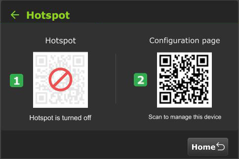
The Hotspot menu selection displays two QR codes. Users can scan the Hotspot QR code to join the pack’s internal Hotspot. Scanning the Configuration page QR code to access the WiFi Configuration page in a Web browser.
- Tap the Gear icon at the bottom of the LCD touchscreen to open the Main menu.
- Tap Hotspot on the Main menu.
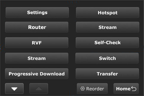
- Use your smart device to scan the [1] Hotspot QR code to join the pack’s network.
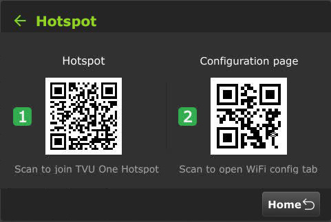
- Once the connection is established, scan the [2] Configuration page QR code to open the web browser window.
The following QR code will be displayed if Hotspot is turned off.
Router
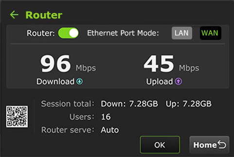
Users can enable the Router on the touchscreen. Once enabled, the Ethernet Port Mode: LAN/WAN selections appear. For detailed information about Router settings and client connections, go to Advanced Settings in the Web UI.
Note: This feature must be enabled by support before it can be used.
To enable the Router Feature:
- Tap the Gear icon at the bottom of the LCD touchscreen to open the Main menu.
- Tap Router on the Main menu.
- The Router screen will display.
- By default, the router setting is off. Tap and move the Router slider to the right until it turns green.
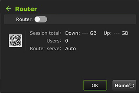
- When the router setting is in the on position, the following screen is displayed.
- Tap an Ethernet Port Mode: LAN or WAN setting. Your selection turns green when enabled.
Switch
The “Switch” mode is a Network switch feature. It’s visible on the Pack LCD touchscreen and is a quick-toggle shortcut for the VLAN Tunnel Switch feature. While the detailed IP networking is usually done via the Web GUI, the LCD screen allows the field operator to engage or monitor the tunnel status without opening a laptop.
To enable the Switch feature on the LCD touchscreen:
- Tap the Gear icon at the bottom of the LCD touchscreen to open the Main menu.
- Tap Switch on the Main menu.
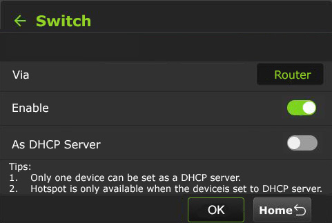
- When enabled, only one device can be set as a DHCP server.
Note: Hotspot is only available when the TVU One is set as a DHCP server.
Stream
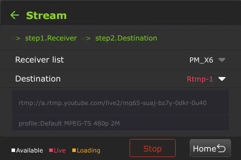
Using the Stream feature, a user can remotely control the stream output destination of a receiver.
To enable the Stream feature on the LCD touchscreen:
- Tap the Gear icon at the bottom of the LCD touchscreen to open the Main menu.
- Tap Stream on the Main menu.
- Select a receiver from the Receiver drop-down list.
- Select one Destination from the drop-down list.
- Tap Publish.

- When the stream is live, the destination output will display red; when loading, the status will be orange. Receivers that are available display white.
- To stop the stream, tap the Stop button.
Self-Check
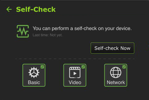
The Self-Check screen enables you to Self-Check your devices’ basic, video, and network health status. TVU Support staff can use this information for troubleshooting purposes.
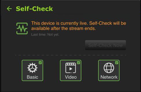
Note: A Self-Check can be initiated while the device is not Live.
To perform a self-check on your device from the LCD touchscreen:
- Tap the Gear icon at the bottom of the LCD touchscreen to open the Main menu.
- Tap Self-Check on the Main menu.
- Tap one or more Basic, Video, and Network checkboxes, then tap the Self-Check Now button to run diagnostics on your device.
Note: If the device is currently live, the following message appears.
- Follow the Self-Check prompts.
- When an issue occurs after self-checking the Basic, Video, or Network modules, the following warning message appears, indicating which module is not functioning correctly.
- Tap the red module to display the configuration issue and make the appropriate correction(s), then tap Self-Check Again.
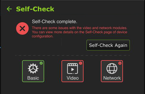
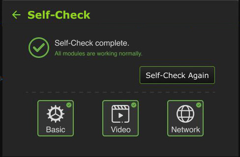
- When the Self-Check completes without any issues, the following message displays.
Progressive Download
The Progressive Download feature lets users to record clips by connecting a video camera to the SDI input. The video camera record button controls the recording. Clips are downloaded, transferred, and taken live using the Pack Control mode.
Note: Camcorder mode applies to video cameras that have SDI with an embedded time code.
The “File-based Workflow Reference Guide” further explains recording.
To use the Progressive Download feature:
- Tap the Gear icon at the bottom of the LCD touchscreen to open the Main menu.
- Tap Progressive Download on the Main menu.
- Continue with “Camcorder mode” or “TVU Pack control mode.”
Camcorder mode
Camcorder mode can only be used with an SDI input. Having the time code inside the SDI signal is required.
To enable Progressive Download Camcorder mode:
- Tap Camcorder and move the slider to the right until it turns green.
- Tap OK.
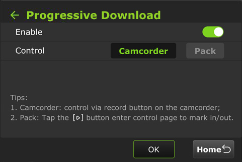
- Press the Record button on the video camera to display its controls.
Standby and Record modes
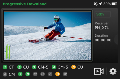
- Standby “Stby” displays in green when in camcorder mode and not recording.
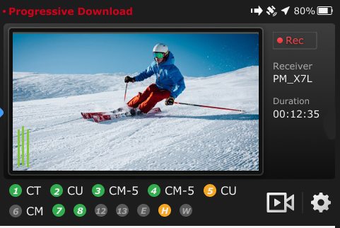
- When the video camera is recording, “• Rec” displays in red.
- When the video camera finishes recording, Standby “Stby” displays in green.
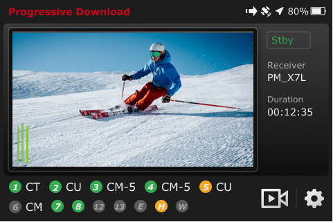
Note: Stop the video camera from recording if you need to change your pack settings.
If you change the settings to Pack while Camcorder mode is running, the following message will display.

If you switch to Camcorder mode while running in Pack mode and the Mark In point is set but the Mark Out point is not, the following message will appear. The processing becomes interrupted and defaults to the current Mark Out point.

When a file transfer is in progress, a new file transfer ⇒ icon displays in the top status bar. If you take the clip live during the transfer process, the following message will display.
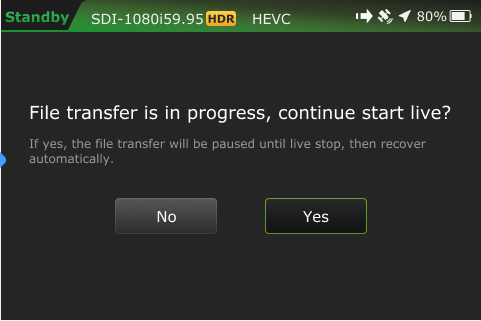
TVU Pack control mode
The Pack Control mode can be used in either SDI or HDMI. A time code is not required. Clips are downloaded, transferred, and taken live using the Pack Control mode.
To enable the Progressive download Pack Control mode:
- Tap Pack and move the slider to the right until it turns green.
- Tap OK. A Success prompt will display.
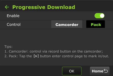
- Tap the Home button. Your feed will display in “Standby” mode.
- Tap the
 icon to enter the control page to set your mark in/out preferences.

When a file is being transferred using the Progressive Download, Download, and Auto Sync methods, a new file transfer ⇒ icon displays in the top status bar of the LCD touchscreen. A prompt will appear if a file is being transferred when the Pack shuts down.
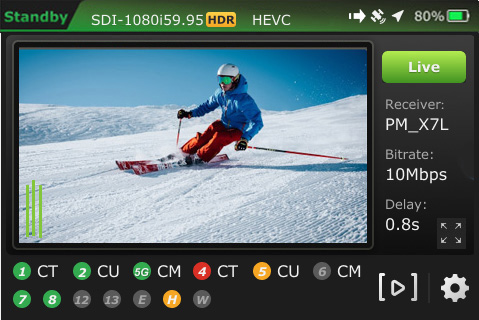
Tap the file transfer ⇒ icon displays when a file is being transferred. Tap the Transfer tab to view the file transfer details.
- The
 icon is red when a Progressive Download is in progress.
 - The camera
 icon is red when the Pack is live with a receiver.
Return Video Feedback (RVF)
This feature requires the Video Feedback Box (VFB) accessory. The TVU One Video Feedback Box is an external device used with TVU One TM1000V3 and v3+ transmitters running software version 6.7 and later.
The return Video Feedback Box is powered via the TVU One USB port and features a mini-HDMI interface for output to an external monitor.
The VFB connects from the TVU One USB port to a mini-HDMI monitor port. When the VFB function is enabled on a TVU One transmitter, it displays the return video feed from a receiver in the field on a monitor in real time.
Refer to the TVU One TM1000V3 Video Feedback Box QSUG for detailed information about setup and usage.
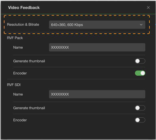
Users can rename the RVF separately from the receiver’s name.
To create a custom duplicate RVF Pack and RVF SDI name:
- Open the Video Feedback configuration panel.
- Enter the new RVF Pack and/or RVF SDI name.
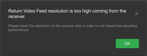
For the V-box adapter, the following message will be displayed if the receiver’s Return Video Feed resolution is set to 1080p or higher, and the bitrate exceeds 2 Mbps.
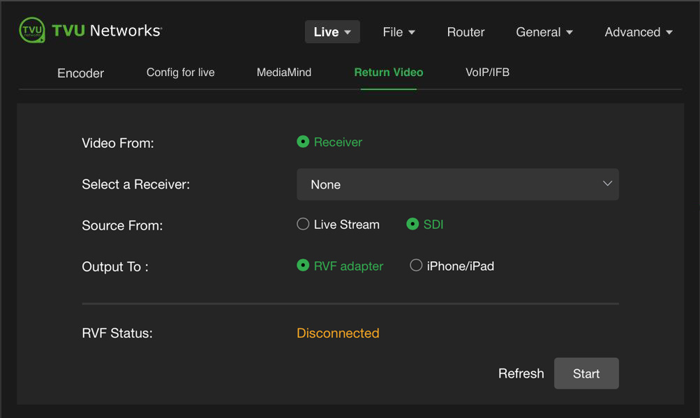
- Open the configuration page, click Live > Return Video.
- Click the Receiver radio button and select a receiver from the drop-down menu.
- Select a Source From radio button (e.g. Live Stream or SDI).
- Select an Output To option.
- Click Start.
To configure the Return Video Feedback from a transmitter:
- Tap the Gear icon at the bottom of the LCD touchscreen to open the Main menu.
- Tap RVF on the Main menu.
- Select a receiver from the drop-down menu.
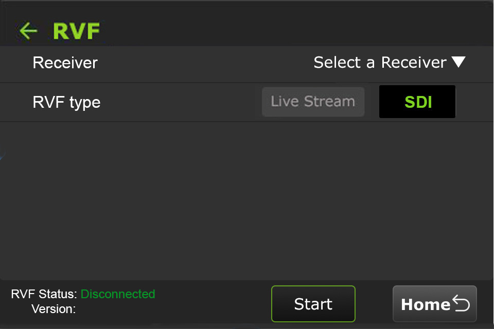
- Select a Live Stream or SDI RVF type and tap Start.
Note: Two sources are available from most transceivers. The currently live pack feed on the receiver or the SDI input to the receiver.
- Tap the back arrow to return to the Main menu or the Home button to return to the status screen.
Upload
The Upload feature allows users to upload files from a USB flash drive to a Receiver.
To upload files:
- Tap the Gear icon at the bottom of the LCD touchscreen to open the Main menu.
- Scroll down and tap Upload.
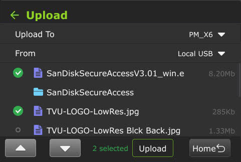
- The Upload screen displays.
- Select a receiver from the “Upload to” drop-down list, then select a USB source in the “From” drop-down list.
- Select the desired files and tap the Upload button.
Transfer
The Transfer feature allows users to view the status of the Progressive Download, Download, and Auto-sync file transfers.
- Tap the Gear icon at the bottom of the LCD touchscreen to open the Main menu.
- Tap the Transfer button.
- The Transfer screen displays.
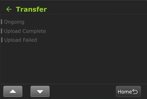
- The green status indicator displays in the Transfer tab’s Ongoing list when the file is being transferred.
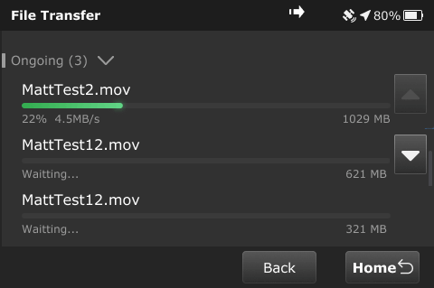
- When the file transfer is complete, the file moves to the Transfer tab’s Complete list.
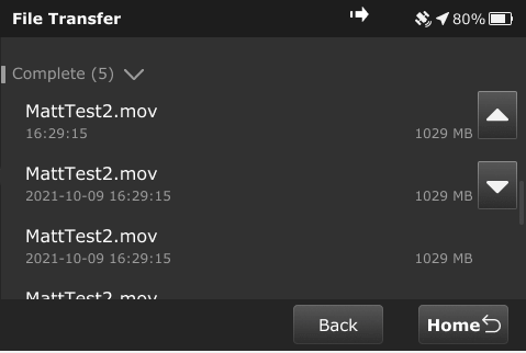
- The following message displays if file transfers are in progress when going live before the transfer completes.
Speedtest
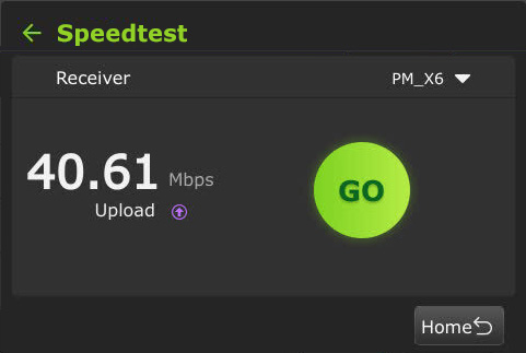
The Speedtest feature in the Main menu allows users to test the speed between the TVU One and the receiver. Unlike a standard smartphone speed test, the TVU One test specifically measures the uplink capacity to the TVU ecosystem.
To run a Speedtest:
- Tap the Gear icon at the bottom of the LCD touchscreen to open the Main menu.
- Scroll down and tap the Speedtest button.
- The Speedtest screen displays.
- Select a Receiver from the drop-down menu.
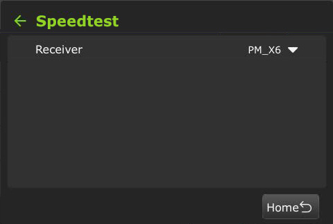
- Tap Go.
USB remote control PTT button operations
- VoIP call operations
- SCTE insertions
Operators can now use a USB remote control as a Push-to-talk (PTT) button for the VoIP microphone. This allows users to mute and unmute the mic when in a VoIP call independently from their headset.
Note: When attempting to click to another control mode while the mic is “Mute” a confirmation message appears. Click Yes to mute and change modes. The Mic will automatically reset.
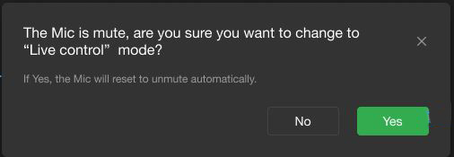
VoIP call operations
To enable the VoIP call Mute/unmute feature:
- Open the local Web interface configuration page.
- Click Advanced > Remote Controller settings.
- Select the Mute/Unmute Mic in VoIP Call radio button.
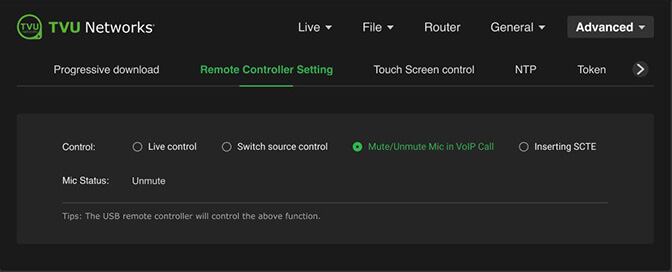
- Connect the USB remote controller device to the TVU Pack. While on a VoIP call, press once to mute.
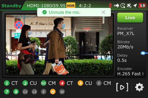
- The Mic Status shows Mute in red.
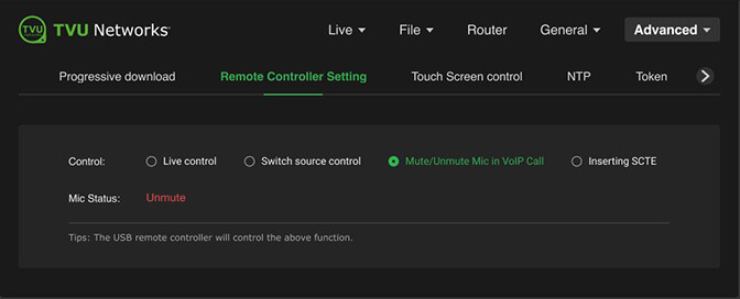
- Press again to unmute.
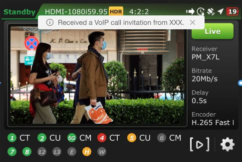
- When a VoIP microphone call invitation is received, the following message will appear automatically on the LCD.
- When VoIP is connected, a white microphone icon appears at the top of the status bar.

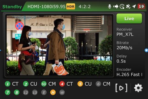
- When using VoIP, the Mic displays a modulating white-and-green icon.

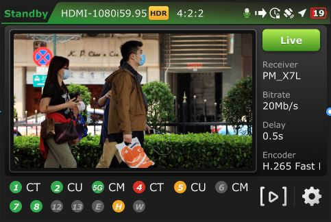
- When you press the remote button, a Mute the mic message appears, and the mic icon turns red, indicating that VoIP is connected and the mic is muted.

- Press the remote button again to unmute the mic. The mic icon will return to the white (connected and open) state.
SCTE insertion
Note: If a user switches to Inserting SCTE when the Mic is Muted, a message will appear asking if you want to change to “Live control,” when this is allowed, the Mic will reset to Mute automatically.
To enable the SCTE insertion option:
- Open the local Web configuration page, click the Advanced menu, and then the Remote Control Setting tab.
- Select the Inserting SCTE radio button to set the control option.
Note: The Duration and Preroll SCTE default values that appear are editable.
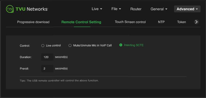
- Plug the USB remote control device into the pack.
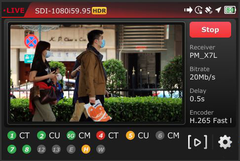
- Press the USB remote button once to begin inserting SCTE. The insertion automatically stops when the duration ends.
- The default duration value is 120 seconds. This value can be edited and will be saved after rebooting the pack.
- The default Preroll value is 2 seconds. This value can be edited and will be saved after rebooting the pack.
- The countdown displays at the top of the LCD screen.
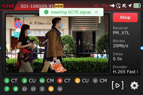
- When the duration ends, the SCTE insertion automatically stops, and the following message displays.
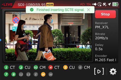
Note: If the user presses the Remote control device button while it’s active, an “SCTE Splice currently in process. Unable to complete the requested action until the current splice duration is complete” message displays on the LCD screen.

Resetting the Duration and Preroll parameters to default values
To change the SCTE parameters back to the SCTE default values:
- Open the Remote Control Setting page.
- Click the Inserting SCTE radio button.
- Click the Reset buttons to change to the default values.
Pack controls
Note: The pack must be live with TVU Channel to display the SCTE button on the LCD touchscreen.
- Tap the Gear icon at the bottom of the LCD touchscreen to open the main Settings menu.
- Scroll down and tap SCTE.
- The SCTE screen displays
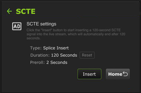
Note: The SCTE parameters need to be synchronized between Config-T and the LCD touchscreen. After modifications, they can be reset to default by using the Reset button.
- Tap the Insert button to add the SCTE signal to the live stream.
- The Insert button will change to a countdown button.
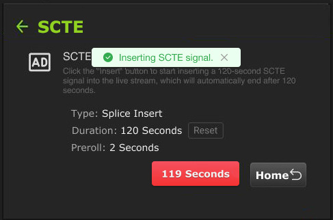
- The countdown will also be displayed on the top bar of the pack’s Home screen.
- The SCTE screen will display a “Finished inserting SCTE signal” message, and the countdown button returns to “Insert.”
- The Pack’s Home screen top bar returns to its Live state without the countdown.
Tally status display
Producers can display Preview (PVW) and Program (PGM) Tally status on their transmitter during live broadcasts.
When the transmitter receives the red tally signal, the On-Air status panel will display, and the video preview will be outlined in red.
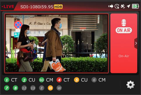
Tap the expansion icon “>” in the red tally panel to return to the Home screen while on-air.
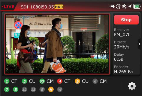
When the transmitter does not receive the tally signal, the Home screen does not display the expansion icon “>” in the right panel.
When the transmitter receives the green tally signal, the Preview status panel will display, and the Video preview will be outlined in green.
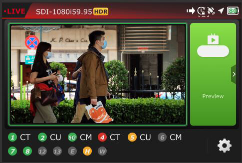
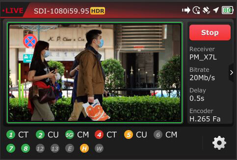
Tap the expansion icon “>” in the tally panel to return to the Home screen while in preview mode.
© Copyright 2026 TVU Networks Corporation. All rights reserved in all media.
Document Part Number: TVU One FHD and 4K Software QSUG Rev M EN 08-2026
Related tips
