Contents
- Setup, configuration, and Going live
- Single and multi-camera connections
- Live status screen functions
- Going live
- Controlling multiple channels
- RPS One config tab
- WiFi
- Hotspot
- Router
- Switch
- 16-Channel Mono and Stereo encoding
- Source Switch
- Stream
- Self-Check
- Progressive download
- Standby and record modes
- Return Video (RVF)
- Upload
- Transfer
- Speedtest
- RPS One Advanced configuration – pack controls
- Connecting to the RPS One hotspot
- Return Video
- IP Source configuration
- Router feature
- Advanced configuration – Web interface controls
- Hotspot configuration
- Modem configuration
- Configuring data cards
- Ethernet Configuration
- Return video
- VoIP Audio inputs
- Advanced Self-Check panel
- Router configuration
- Audio encoding
TVU RPS One Model TM1100 Software QSUG v8.3
Before you begin
Before you use your TVU RPS One encoder, refer to the latest TVU RPS One Model TM1100 Hardware Quick Start User Guide to set up the hardware and identify the devices you intend to use with the unit, including cameras, cables, power sources, modems, TVU services, and unit accessories.
The TVU RPS One encoder running The One/RPS One Software version 8.3 (Build 83128) or later uses the same hardware, which features two LCD console interfaces:
- The One single-channel transmitter
- TVU RPS One multi-channel encoder
Note: To switch from a One to an RPS One console, contact TVU Support at support@tvunetworks.com. Once authorized, switching consoles is performed automatically. A reboot is necessary.
Single and multi-camera connections
The encoder’s LCD screen can be operated using single or multi-channel inputs. For input connection configurations and “Multi-Channel connections and behaviors,” refer to the following figures.
The following camera combinations are supported:
HDMI only – Up to 4K p60
12G SDI In (1) only – Up to 4K p60
Up to 4 3G SDI In – Up to 1080 p60
About this guide
This software quick-start user guide provides information on performing basic configuration and operating the TVU RPS One encoder.
- Refer to the TVU RPS One Model TM1100 Hardware Quick Start User Guide to set up your hardware.
Turning on the RPS One
- Press the power button, and the RPS One transmitter will begin to boot up.
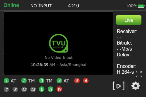
- The initial status screen will display.
- The modems begin to connect automatically.
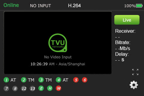
When no transmission feed is connected to the unit, “No video input” will display on the LCD touchscreen.
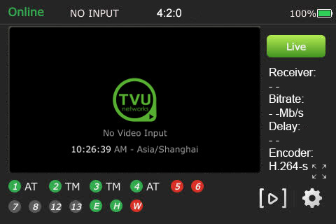
Note: you may be prompted to upgrade your firmware. If you choose to upgrade, click the notification at the top of the status screen. It may take up to 30 minutes to complete.
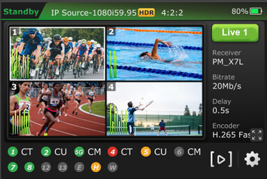
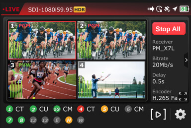
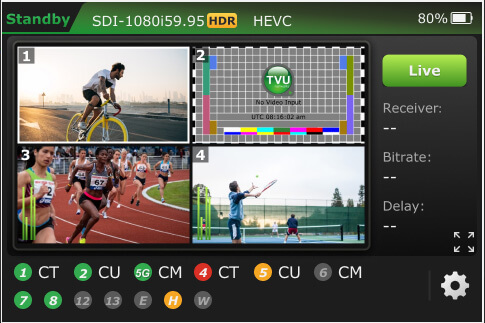
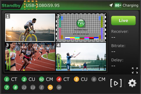
TVU RPS One encoder Live status screen functions
When SDI is connected, field transmission control is enabled.
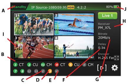
(A) Transmission Status: The LCD touchscreen displays the RPS One’s current transmission status. When video input sources (SDI 1-4) are connected to the RPS One encoder, the touchscreen will display Standby until a channel is selected and taken “Live.”
(B) Data Card Status Monitor:
The status monitor displays the current number and status of all data cards connected to the RPS One. The status of data cards connected to the encoder will appear as green, red, orange, or black. Green status indicates that the data card is connected. Orange status indicates that the data card is attempting to dial. Red status indicates that the data card is not connected. Black status indicates that no card is present.
(C) Ethernet Connection: Displays the status of the Ethernet connection.
(D) Hotspot Connection: Displays the status of the hotspot connection.
(E) WiFi Connection: Displays the status of the WiFi connection.
(F) Latency Status: Displays the current latency of the transmission.
(G) Bit Rate Status: Displays the current Bit Rate (B/R).
(H) Receiver Name: Shows the receiver name to which the unit is transmitting.
(I) Audio Input Level Monitor: This monitor dynamically displays the unit’s audio input level (DBFS) with graphical colors.
(J) Battery Status: Indicates the battery’s status.
Going Live
To go live using the receiver with which you last went live:
- Tap the Live button on the initial status screen to start the live transmission.
- The RPS One unit will prompt you to slide the ‘Slide to go live’ button from left to right.
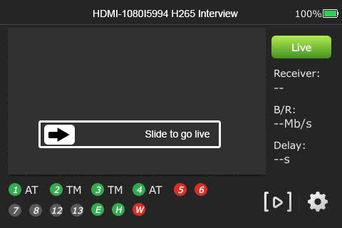
- Once the button is engaged, the RPS One begins the live transmission using the last receiver with which you most recently went Live.
Selecting a receiver and going Live
To select a receiver, configure your settings, and go Live, complete the following steps:
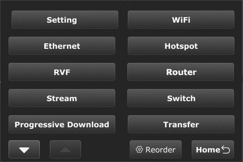
- Tap the Settings gear icon on the bottom right of the LCD touchscreen.
- The new menu will display. The new menu allows users to reorder, remove, and add menu options to customize the menu order based on user habits.
Note: The Setting,WiFi, and Hotspot buttons can not be removed.
- Tap the Setting button.
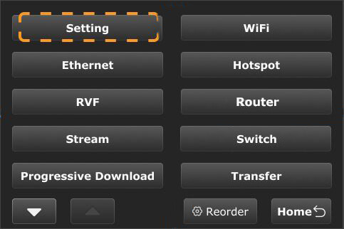
Note: To return to the previous screen, tap the Home button.
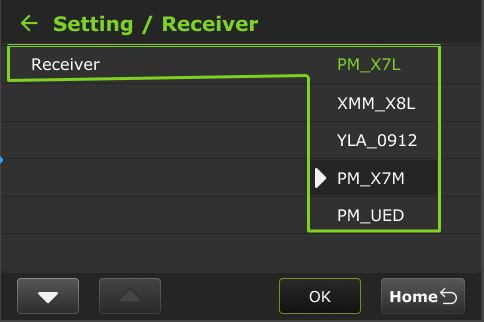
- The Setting menu will display, tap the Receiver menu.
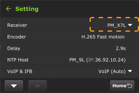
- Select the receiver you want to go live with from the drop-down menu, then tap OK, then tap the Go Live button.
- If you only want to select a receiver but do not want to go Live, tap the Home button at the bottom-right corner of the LCD touchscreen.
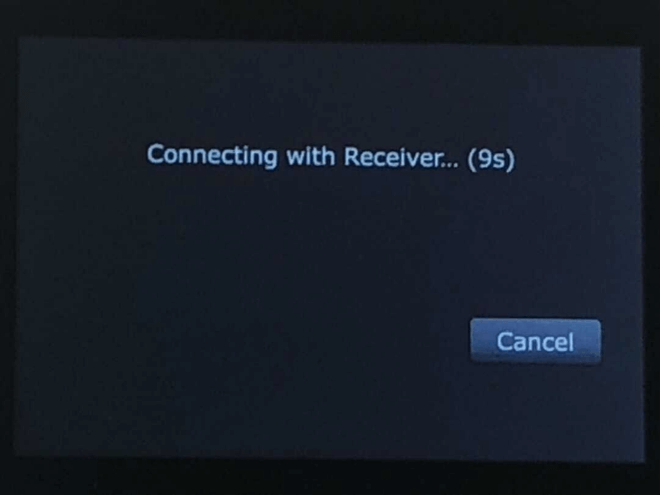
Note: When starting a live transmission from this menu, you will not be prompted to slide a button. The transmission will begin with a countdown.
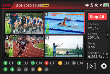
Controlling multiple channels
- Tap a channel, then the green Live button.
- When a channel is live with a receiver, “PGM” appears next to the channel number in the top-left corner of the preview screen.
- Press and hold the channel number preview to stop a Live transmission until the red Stop button displays.

- When the live transmission is stopped, the LCD displays “Standby” in the top-left corner of the screen.
- A message will be displayed if a live transmission fails after reboot.
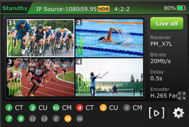
Multi-channel operational modes
This section explains the RPS One operational modes and the expected behavior for each mode.
Users can select a multi-channel (group control) or single-channel (single mode) transmission on the touchscreen.
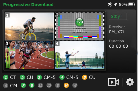
The RPS One displays the four connected SDI video input previews on the LCD touchscreen. It has two operational modes: single and group control. The RPS One default is group-control mode.
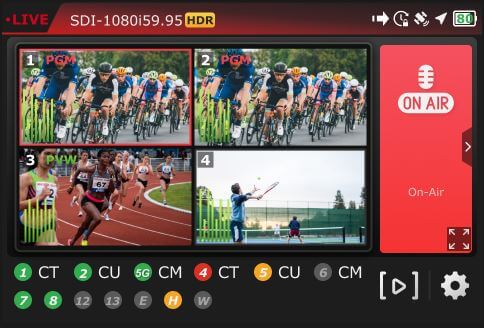
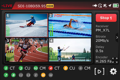
Multi-channel preview 1- 4 behavior
The video preview number displayed in the top-left corner of each video preview corresponds to the SDI video input channel.
- The Live source displays a red “PGM” next to the channel number on the top left of the video preview screen.
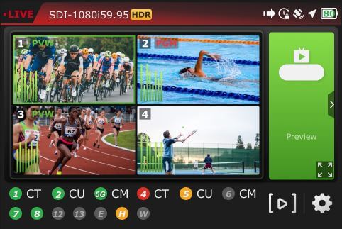
- When the source is in Preview mode, the video preview screen displays a green “PVW” next to the slot number in the top-left corner.
- Only the channel number will be displayed when a source is not in PVW or PGM mode.
- Tap a video preview to enter the group-control mode (default).
- Tap and hold a video preview for 3 seconds to control the channel independently. To control another channel and return to group-control mode, wait 20 seconds between selections, then press another preview.
- Tap the video preview, then the full-screen icon to enable the full-screen preview.
- Tap a PGM or PVW video preview, then the “>” in the right panel to display the Tally banner.
Starting and stopping a multi-channel transmission
- The Live All button will display on the LCD touchscreen when all channels are detected.
- Tap a live preview and the Stop All button on the LCD touchscreen to stop all live multi-channel transmissions.
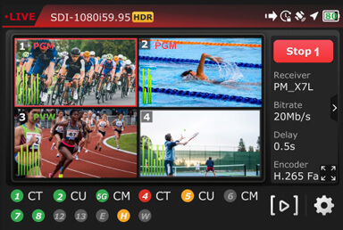
Starting and stopping a single-channel transmission
To start a single-channel transmission:
- Tap a video preview and press for two seconds.
- Tap the Live button. You will notice that the selected channel number will be displayed on the “Live” button.
- When the channel is transmitting, the preview window will be framed in red, and “PGM” will display in red next to the channel number.
- To take another preview live, wait 20 seconds and repeat the process.
To stop a single-channel live transmission:
- Tap, press, and hold the channel number preview.
- Tap the red Stop button.
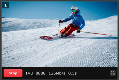
Full-screen preview
To enable single full-screen views from the touchscreen.
- Select a channel and tap the full-screen icon.
- To return to the multi-view display, tap the bottom-right icon.
RPS One configuration settings
This section describes the list of RPS One pack settings and explains how to locate and configure them.
- Tap the Gear icon on the initial status page.
- The main menu will be displayed. Tap the Setting button to open the configuration setting page.
Selecting an encoder option
The TVU RPS One has true dual encoding. It encodes the same content at a fixed bitrate in the background and records to local storage. Users can monitor the live-stream bitrate. A visual notification is displayed on the home screen if the selected transmission bitrate drops below the threshold.
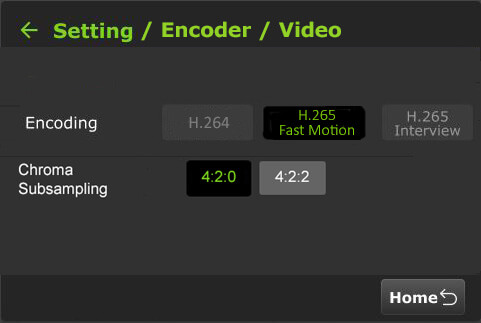
The TVU RPS One model TM1100 supports onboard H.265/HEVC or H.264 encoding.
To select an encoding option:
- Tap the Setting button on the main menu to open the Setting screen, then tap Encoder.
- Select an input Source channel.
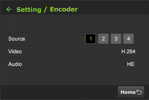
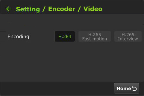
- Tap Video to open the Video Encode menu.
- Configure the Encoding and HDR/HLG settings.
HDR / HLG Explained
HDR (High Dynamic Range) increases contrast and color range, displaying brighter highlights and deeper shadows for more realistic images.
HLG (Hybrid Log-Gamma) is a type of HDR designed for broadcast; compatible with both HDR and standard displays without needing metadata, making it ideal for live production.
Using 8-bit with HDR/HLG often results in visible artifacts, especially in smooth gradients. For effective HDR, 10-bit or higher is strongly preferred.
The Disabled HDR/HLG option disables HDR/HLG decoding or 10-bit.
When the device is live with a low version receiver that does not support 10-bit, the following error message will be displayed.
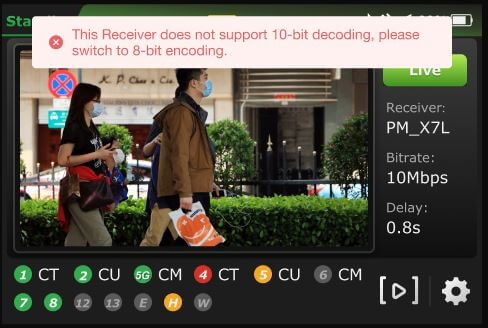
Note: Your selection will highlight green. The RPS One must be in live mode before you can change selections.
Chroma Subsampling: 4:2:0 vs 4:2:2
Chroma subsampling reduces color information to save bandwidth while preserving image detail.
- 4:2:0 samples color at half the horizontal and vertical resolution; best for streaming or storage-efficient video with lower color fidelity.
- 4:2:2 samples color at full vertical resolution and half horizontal; preserves more color detail, preferred for professional editing or broadcast.
- H.265 Interview
- H.264 Normal
- H.265 Fast Motion
- Tap the Back Arrow.
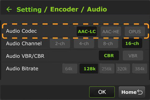
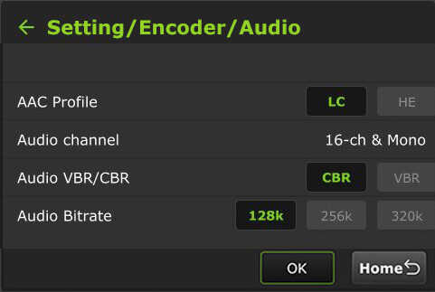
- Tap Audio to open the Audio Encode menu.
Audio Codec descriptions:
Advanced Audio Coding (AAC)
AAC is a versatile audio compression format known for delivering high-quality sound with efficient file sizes.
AAC-LC (Low Complexity):
AAC-LC is a specific profile within the AAC format, optimized for lower computational complexity and broad compatibility. It offers excellent sound quality while being easier to decode, making it ideal for devices with limited processing power. AAC-LC is commonly used on platforms such as iTunes, YouTube, and digital radio.
AAC-HE (High Efficiency):
AAC-HE, also known as AAC+ or AAC Plus, is an extension of the AAC format designed for even greater compression efficiency. It utilizes more advanced encoding techniques to achieve higher compression ratios, reducing file sizes without significant loss of audio quality.
AAC-HE is particularly suited for low-bitrate applications such as streaming over limited bandwidth or storing audio on devices with constrained storage capacity
OPUS Audio Codec:
OPUS is a highly versatile and efficient audio codec designed for interactive, real-time audio applications like voice calls, video conferencing, and live streaming. It is widely adopted for delivering high-quality audio at low bitrates, making it perfect for modern communication and entertainment platforms.
- Make your Audio Encode selections. The Audio Codec now includes an OPUS option alongside the two AAC profile options.
- To return to the Encoder menu, tap the back Arrow.
- To return to the Setting screen, tap the back Arrow again.
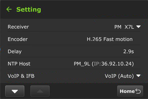
Delay management
To manage the second and sub-second Latency settings:
- Tap the Setting button to open the Setting screen.

- Tap Delay to configure the latency.
- Tap a box and use the up and down buttons to set the delay.
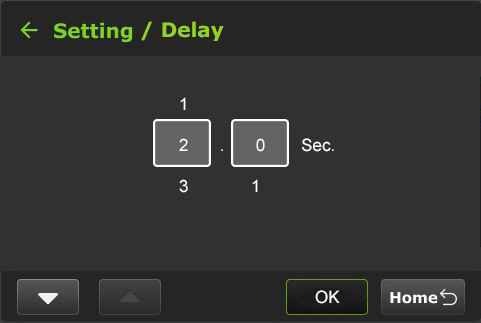
- Tap OK to confirm your settings. To return to the Setting screen, tap the back Arrow.
NPT Host
Users can view the NTP host status at the touchscreen display. The NTP Host IP address is configured in the Advanced settings Web UI panel.
VoIP & IFB
Users can configure VoIP and IFB for both single-channel and multiple-channel scenarios.
VoIP & IFB – Single-channel configuration
To configure VoIP and IFB settings for a single channel:
- Tap the Setting button to open the Setting screen.
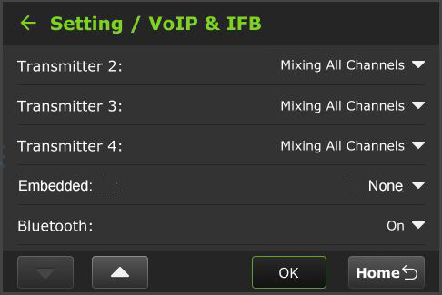
- Tap VoIP & IFB to configure the settings.
- The Setting / VoIP & IFB config will display.
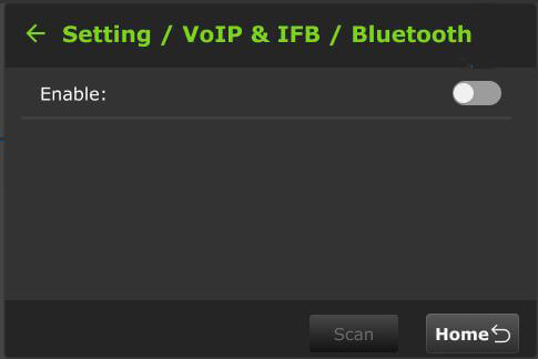
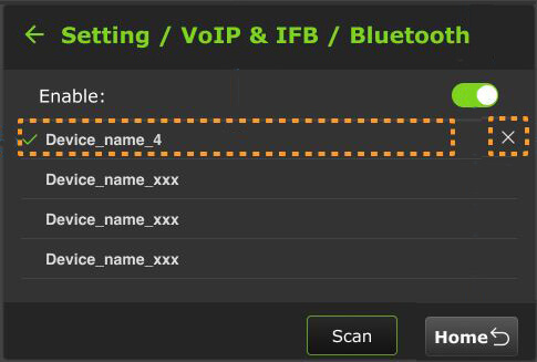
- Tap the down button, then tap Bluetooth.
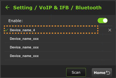
- Enable the slider.
- The currently connected device will display a green checkmark when the bluetooth is enabled.
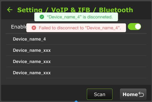
When you tap the currently connected device, it will disconnect, and one of the following messages will be displayed.
You must disable the slider before disconnecting the device.
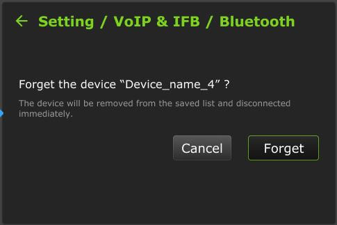
- To remove a device from the saved set, tap the “X”.
- A confirmation to “Forget” the device will be displayed.
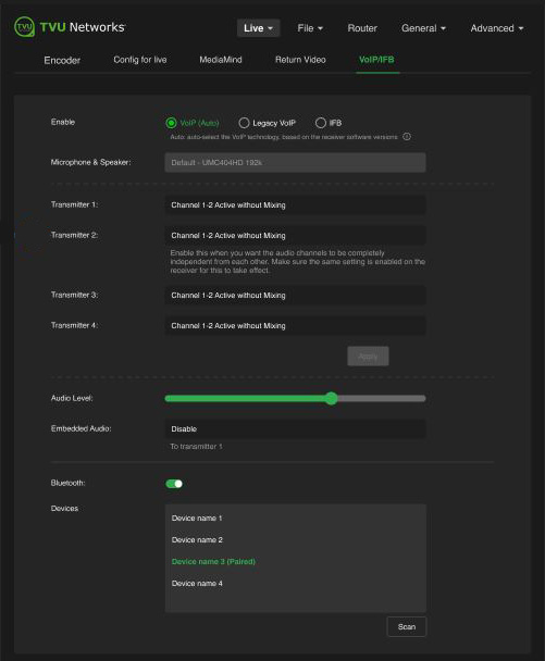
VoIP & IFB – Multiple-channel configuration
To configure VoIP and IFB settings for multiple channels:
- Tap the Setting button to open the Setting screen.
- Tap VoIP & IFB to configure the settings.
- The Setting / VoIP & IFB config will display.
- Tap the down Arrow to ensure that Bluetooth is enabled “On”.
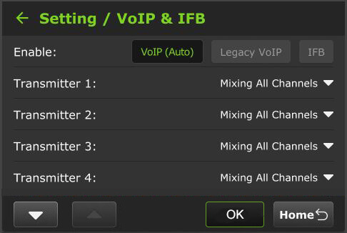
- Select a Transmitter to configure.

- Select the Audio Setting from the menu.
- Tap OK.
Data card monitoring
To monitor detailed encoder information along with Ethernet, hotspot, and WiFi connections:
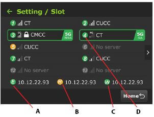
- Tap the Gear icon, then the Setting button to open the Setting screen, then tap Slot.
- The data cards and their status display along with Ethernet, Hotspot, and WiFi indicators:
(A) Ethernet
(B) Hotspot
(C) WiFi connection
(D) Slot number
Slot speed
A user can view the speed of each slot in real-time. To view a slot speed:
- Tap the “>” to view the real-time speed of a slot. The selected slot is framed in green.
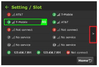
- The real-time speed of the slots is displayed.
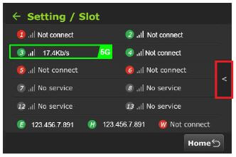
- To return to the slot screen, tap the “<” icon.
- To return to the Setting screen, click the Back Arrow.
RPS One transmitter information (About)
To access the RPS One model number, Peer ID, software version, App version, the designated ISX or IS+ mode, and region:
- Tap the Gear icon, then the Setting button to open the Setting screen.
- Scroll down and tap About.
- The Setting / About information window displays.
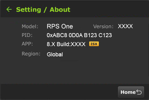
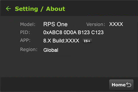
- To return to the Setting screen, tap the Back Arrow.
Language selection
Users can choose English or Chinese.
To select a language:
- Tap the Gear icon, then the Setting button to open the Setting screen.
- Scroll down to tap the Language option. The default is English.
- Select your location option using the up and down arrows.
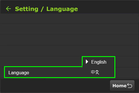
- To return to the Setting main menu, tap the back Arrow twice.
WiFi
The pack will automatically attempt to reconnect if the current WiFi connection disconnects.
When multiple WiFi adapters are connected, you can scan available slots for WiFi adapters and configure the WiFi login information on the Pack’s LCD screen or by using the RPS One WiFi setup and configuration panel. For detailed information, refer to “WiFi configuration and settings.”
To confirm the RPS One’s WiFi status:
The “W” icon at the bottom of the initial status screen will display green when WiFi is connected.
To configure WiFi:
- Tap the Gear icon on the initial status screen to open the Setting screen, then tap the WiFi button.
- If you don’t see the name, tap the Scan button to refresh the screen.
- Tap the WiFi name you want to connect to.
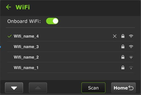
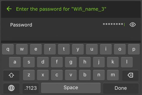
- The virtual keyboard will display.
- Enter the Password and tap Done.
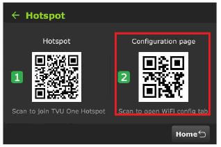
Hotspot
The Hotspot tab displays two QR codes. Users can scan the Hotspot QR code to join the packs’ internal Hotspot. Scanning the Configuration page QR code opens the WiFi Configuration page in a Web browser.
- Tap the Settings (gear) icon on the LCD touchscreen.
- Tap the Hotspot button.
- Use your smart device to scan the Hotspot QR code to join the pack’s network.
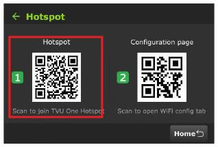
- Once the connection is established, scan the Configuration page QR code to open the web browser window.
- For more information about the Hotspot feature and client connections, refer to “Configuring hotspot.”
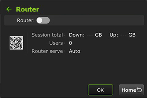
Router
Users can enable the Router on the touchscreen. Once enabled, the Ethernet Host slider appears.
Note: This feature must be enabled by support before it can be used.
To enable the Router Feature:
- Tap the Settings (gear) icon on the LCD touchscreen.

- The Setting menu will display. Tap the Router button. By default, the router setting is off. Tap and move the router slider to the right until it turns green.
- When the router setting is enabled, the following screen displays.
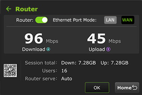
- Select the Ethernet Port Mode. For Advanced Router configuration and Ethernet LAN/WAN settings, refer to “Router feature.”
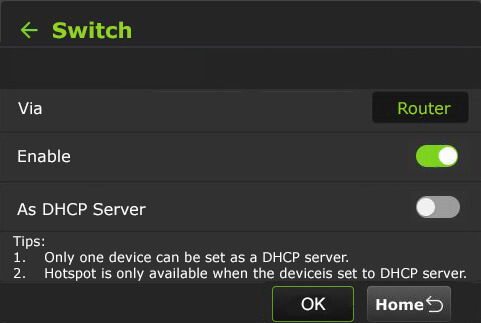
Switch
The “Switch” mode is a Network switch feature. It’s visible on the pack LCD touchscreen is a quick-toggle shortcut for the VLAN Tunnel Switch feature.
While detailed IP networking is usually done via the Web GUI, the LCD screen allows the field operator to monitor or engage the tunnel status without opening a laptop.
To enable the Switch feature on the LCD touchscreen:
- Tap the Gear icon on the initial status screen.
- The Setting main menu will display. Tap the Switch button.
- When enabled, only one device can be set as a DHCP server.
Note: Hotspot is only available when the RPS One is set as a DHCP server.
16-Channel Mono and Stereo encoding
The RPS One supports 16-channel Mono and Stereo Audio Encoding.
To configure 16 Mono and Stereo channels (default) on the Pack’s LCD touchscreen:
- Tap the Settings (gear icon) before going Live. The main setting menu will be displayed.

- Tap the Setting button > Encoder.
- Tap Audio to display the Audio Channel. The 16-Ch default is set to Stereo.
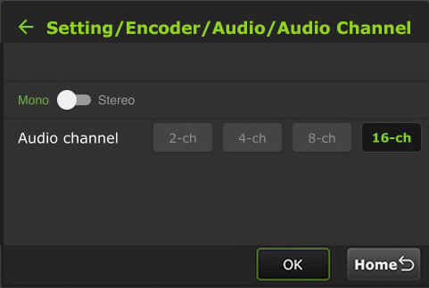
- Move the slider to Mono and tap OK.
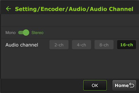
- Tap the back Arrow to verify the Audio Channel mono setting.
Source Switch
By selecting the Source Switch button, a user can enable the Source Switcher mode to switch between sources 1, 2, 3, and 4 from the touchscreen and output to a single receiver. Alternatively, users can control SDI Source Switching using a Keyboard or Web UI.
The v8.3 Source Switch introduces the ability to:
- Toggle focus: Switch between physical inputs (SDI 1-4 or HDMI) for monitoring or primary transmission.
- Mode Selection: Choose between Multi-Channel Mode (sending all 4 cameras) and Single Source Mode (prioritizing one camera for maximum bitrate/quality).
- Local Preview: Use the 3.5-inch pack LCD to “switch” through your inputs to verify signal integrity without an external monitor.
It is important not to confuse Source Switching (Video) with VLAN Switch Mode (Networking).
- Source Switch: Changes what video is being encoded (Input 1 vs. Input 2).
- VLAN Switch Mode: Changes how the data is routed (Layer 2 bridge for PTZ/CCU control).
The “Source Switch” capability is handled through two primary methods: the Physical Pack Interface (for quick field checks) and the Web GUI (for production routing).
To enable the Source Switch feature via Pack LCD:
- Tap the Gear icon on the initial status screen.
- The Setting main menu will display.
- Scroll down the menu and tap the Source Switch button.
- The Source Switch screen will be displayed.
- Enable the Source Switcher slider.
- Move the Add to Home Screen toggle to the right until it turns green to add the switch to the Home screen.
- Select one receiver from the Receiver drop-down menu. The default receiver is the one you are currently live with.
Note: it is not possible to output each source to unique receivers in this mode.
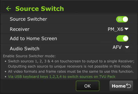
- Select an audio switch setting from the AFV menu.
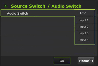
- This option determines the audio source for the SDI Source Switcher. Your menu selections are:
- Default – AFV: Audio follows the video, switching with it.
- Input 1: The audio always comes from Input 1, regardless of the selected SDI source.
- Input 2: The audio always comes from Input 2, regardless of the selected SDI source.
- Input 3: The audio always comes from Input 3, regardless of the selected SDI source.
- Input 4: The audio always comes from Input 4, regardless of the selected SDI source.
Note: When the device is live, the receiver settings cannot be modified and the audio cannot be locked to the source that has no video input.
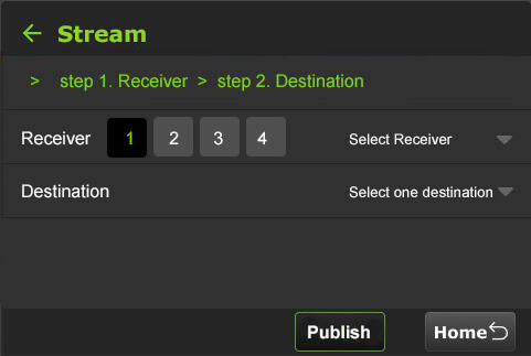
Stream
Using the Stream tab, a user can remotely control the stream output destination of a receiver.
To enable the Stream feature on the LCD touchscreen:
- Tap the Gear icon on the initial status screen.
- The Setting main menu will display. Tap the Stream button.
- Select a channel and a receiver from the Receiver list drop-down menu. Then select a destination from the Destination drop-down menu and tap Publish.
- To stop the stream, tap Stop.
Note: When the Stream is Live the destination selected displays red, when loading the status is yellow. Receivers that are available display white.
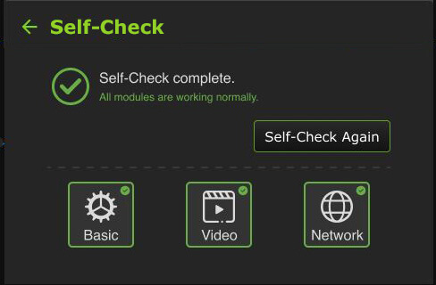
Self-Check
The Self-Check panel enables you to self-check your devices’ basic, video, and network health status while the device is not live.
TVU Support staff can use this information for troubleshooting purposes. This feature can also be accessed in the Advanced configuration Self-Check tab. This is further explained in “Advanced Self-check panel.”
To perform a self-check on your device from the LCD screen:
- Tap the Gear icon on the initial status screen.
- Scroll to the bottom of the Main setting menu, then tap the Self-Check button.
- Tap one or all Basic, Video, and Network checkboxes and tap the Self-check Now button.
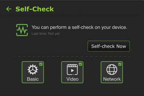
- Tap the Self-check Now button to run diagnostics on your device.
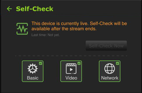
- Follow the prompts.
- If the pack is live, the following message displays.
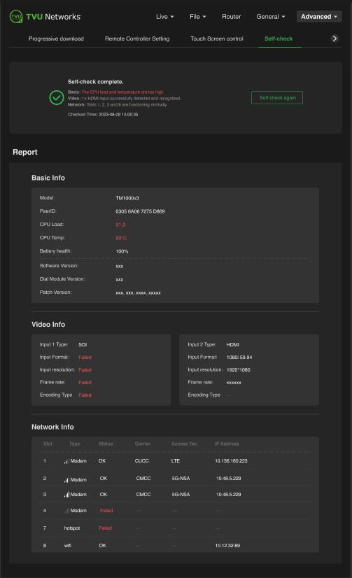
- When an issue occurs after self-checking the Basic, Video, or Network modules, the following warning message appears, indicating which module is not performing correctly.
- Tap the red module to display the configuration issue and make the appropriate correction(s), then tap Self-Check Again.
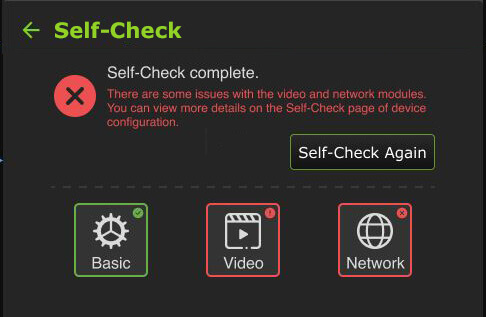
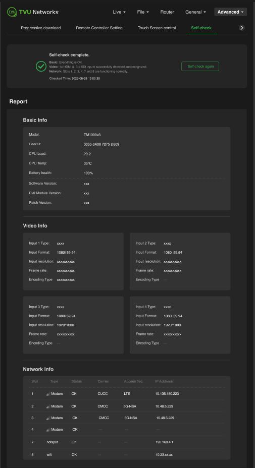
When the Self-Check completes without any issues, the following message displays.
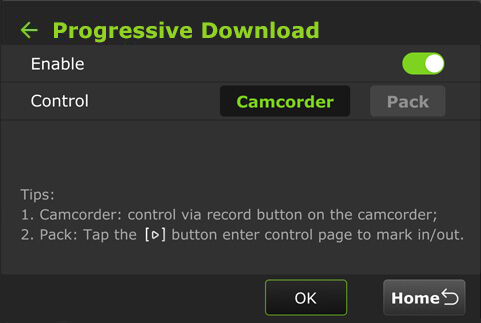
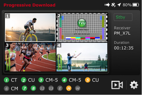
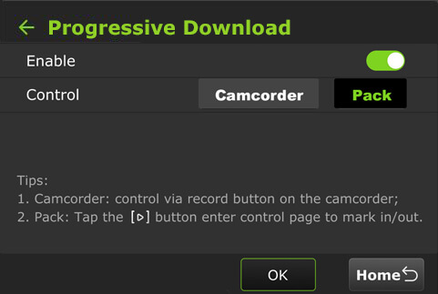
Progressive Download
Enabling the Progressive download feature allows users to record clips by connecting a camcorder to the SDI input. The camcorder record button controls the recording. Clips are downloaded, transferred, and taken live using the Pack Control mode.
The File based workflows in Camcorder or Pack mode in the “File-based Workflow Reference Guide” further explains recording.
To use the Progressive Download feature:
- Select a channel and tap the gear icon to open the Settings screen.
- Tap the Progressive Download button from the main menu.
- Continue to “Camcorder mode” or “TVU Pack control mode.”
Camcorder mode
Camcorder mode can only be used with an SDI input. The time code must be inside the SDI signal.
- Tap the Camcorder button, then slide the slider to the right until it turns green.
- Tap OK.
- Press the Record button on the video camera to display its controls.
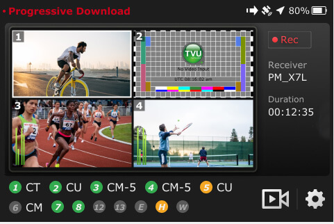
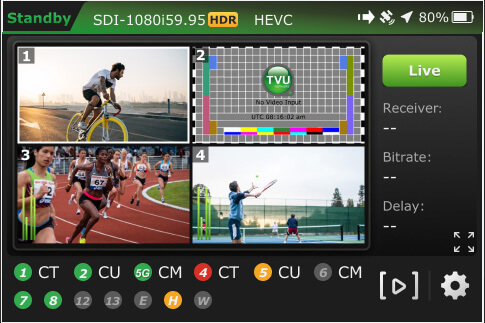
Standby and Record modes
- Standby “Stby” displays in green when in camcorder mode and not recording.
- When the video camera is recording, “•Rec” displays in red.
- Standby “Stby” displays in green when the video camera is finished recording.
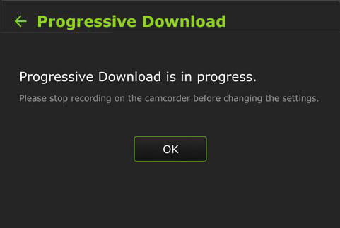
Note: Stop the video camera from recording if you need to change your pack settings.
If you change the settings to the Pack while Camcorder mode is running, the following message will appear:
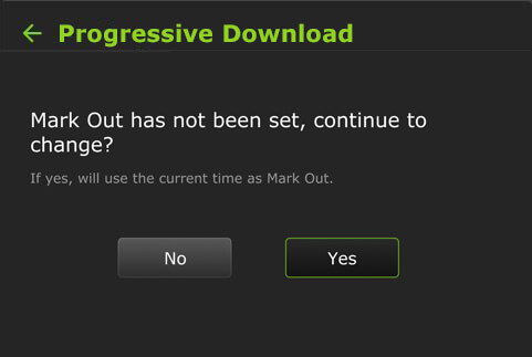
If you switch to Camcorder mode while running in Pack mode and the Mark In point is set but the Mark Out point is not, the following message appears. Processing is interrupted and defaults to the current Mark Out point.
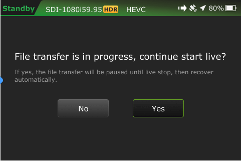
A new file transfer ![]() icon displays in the top status bar when a file transfer is in progress. If you take the clip live during the transfer process, the following message will display:
icon displays in the top status bar when a file transfer is in progress. If you take the clip live during the transfer process, the following message will display:
TVU Pack control mode
Pack control mode can be used in either SDI or HDMI. A time code is not required. Clips are downloaded, transferred, and taken live using the Pack Control mode.
To enable the Progressive Download Pack mode:
- Select a channel and tap the Settings gear icon.
- Tap the Progressive Download tab.
- Tap Pack, then move the enable slider to the right until it turns green.
- Tap OK. A Success prompt is displayed.
- Tap the Home button. Your feed will display in “Standby” mode.
- Tap the
 icon to enter the control page to set your mark-in/out preferences.
When a file is being transferred using the Progressive Download, download, and Auto Sync, methods a new file transfer ![]() icon displays in the top status bar of the LCD touchscreen. A prompt will appear when a file is being transferred as the Pack shuts down.
icon displays in the top status bar of the LCD touchscreen. A prompt will appear when a file is being transferred as the Pack shuts down.
The transfer ![]() icon displays when a file is being transferred. Tap the Transfer tab to view the file transfer details.
icon displays when a file is being transferred. Tap the Transfer tab to view the file transfer details.
- The
 icon is red when a Progressive Download is in progress.
 - The camera
 icon is red when the RPS One is live with a receiver.
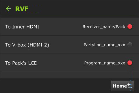
Return Video Feedback (RVF)
Version 8.2 and later support separate Return Video Feedback with the Pack and an RPS receiver.
The Return Video screen has three modes, allowing users to set up RVF from a Receiver, Producer, Partyline, or MediaHub session. These modes can be output to:
- Inner HDMI
- V-box 2 (HDMI 2)
- The Pack’s LCD
Note: When enabled, a single return video can be simultaneously output to multiple outputs, such as two HDMI ports, the Pack’s LCD screen, and a phone or tablet.
All return video feed type settings are accessed from the initial screen Settings gear icon > Main Setting menu > RVF button.
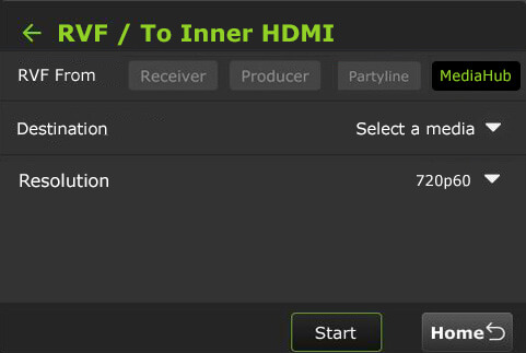
To Inner HDMI – RVF from a receiver
To set up RVF from a Receiver To Inner HDMI:
- Tap the Main Setting menu > RVF button.
- In the To Inner HDMI panel, tap Click here to set up.
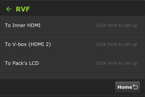
- The RVF / To Inner HDMI screen will display.
- In the RVF From panel, tap Receiver.
- Select a Receiver from the Receiver list drop-down menu.
- In the Source From panel, select Live Stream or SDI.
- Select a Resolution.
- Tap Start.
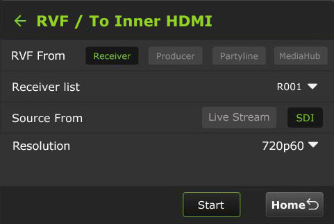
- Tap the circle to select your output(s). Selections will turn red.
- Tap the Home button.
To Inner HDMI – RVF from Producer
To set up RVF from a Producer session To Inner HDMI:
- Tap the Main Setting menu > RVF button.
- In the To Inner HDMI panel, tap Click here to set up.
- The RVF / To Inner HDMI screen will display.
- In the RVF From panel, tap Producer.
- Select a Program from the Select Program drop-down menu.
- Select a Resolution.
- Tap Start.
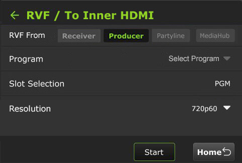
- Tap the circle to select your output(s). Selections will turn red.
- Tap the Home button.
To Inner HDMI – RVF from Partytline
To set up RVF from a Partyline session To Inner HDMI:
- Tap the Main Setting menu > RVF button.
- In the To Inner HDMI panel, tap Click here to set up.
- The RVF / To Inner HDMI screen will display.
- In the RVF From panel, tap Partyline.
- Select a Partyline Source.
- Select a Resolution.
- Tap Start.
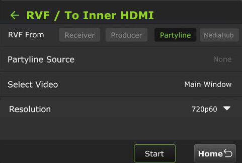
- Tap the circle to select your output(s). Selections will turn red.
- Tap the Home button.
To Inner HDMI – RVF from MediaHub
To set up RVF from a MediaHub session To Inner HDMI:
- Tap the Main Setting menu > RVF button.
- In the To Inner HDMI panel, tap Click here to set up.
- The RVF / To Inner HDMI screen will display.
- In the RVF From panel, tap MediaHub.
- Select a Media Destination.
- Tap Start.
- Tap the circle to select your output(s). Selections will turn red.
- Tap the Home button.
To V-box (HDMI 2) – RVF from a receiver
To set up RVF from a Receiver To V-box (HDMI 2):
- Tap the Main Setting menu > RVF button.
- In the To V-box (HDMI 2) panel, tap Click here to set up.
- The RVF / To V-box (HDMI 2) screen will display.
- In the RVF From panel, tap Receiver.
- Select a receiver from the Receiver list drop-down menu.
- In the Source From panel, select Live Stream or SDI.
- Tap Start.
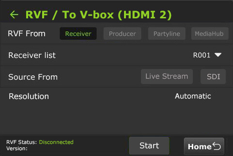
- Tap the circle to select your output(s). Selections will turn red.
- Tap the Home button.
To V-box (HDMI 2) – RVF from Producer
To set up RVF from a Producer session To V-box (HDMI 2):
- Tap the Main Setting menu > RVF button.
- In the To V-box (HDMI 2) panel, tap Click here to set up.
- The RVF / To V-box (HDMI 2) screen will display.
- In the RVF From panel, tap Producer.
- Select a Program from the Select Program drop-down menu.
- Tap Start.

- Tap the circle to select your output(s). Selections will turn red.
- Tap the Home button.
To V-box (HDMI 2) – RVF from Partyline
To set up RVF from a Partyline session To V-box (HDMI 2):
- Tap the Main Setting menu > RVF button.
- In the To V-box (HDMI 2) panel, tap Click here to set up.
- The RVF / To V-box (HDMI 2) screen will display.
- In the RVF From panel, tap Partyline.
- Select a Partyline Source.
- Tap Start.
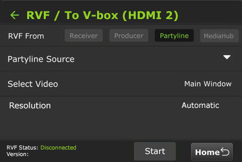
- Tap the circle to select your output(s). Selections will turn red.
- Tap the Home button.
To V-box (HDMI 2) – RVF from MediaHub
To set up RVF from a MediaHub session To V-box (HDMI 2):
- Tap the Main Setting menu > RVF button.
- In the To V-box (HDMI 2) panel, tap Click here to set up.
- The RVF / To V-box (HDMI 2) screen will display.
- In the RVF From panel, tap MediaHub.
- Select a Media Destination.
- Tap Start.
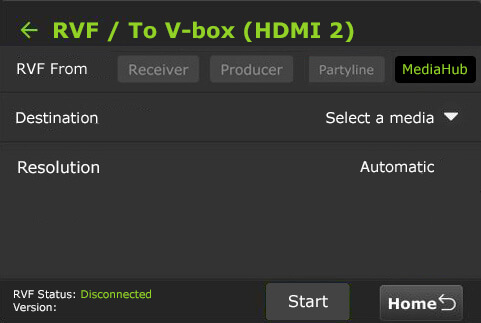
- Tap the circle to select your output(s). Selections will turn red.
- Tap the Home button.
To Pack’s LCD – From a receiver
The VFB connects from the transmitter’s HDMI Out port. When the VFB function is enabled on an RPS TVU One, the VFB allows the return video feed to be transferred from a receiver in the field and displayed on the Pack LCD in real time.
To set up the RVF from a receiver:
- Tap the Main Setting menu > RVF button.
- In the To Pack LCD panel, tap Click here to set up.
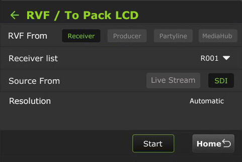
- The RVF / To Pack LCD screen will display.
- In the RVF From panel, tap Receiver.
- Select a receiver from the Receiver list drop-down menu.
- In the Source From panel, select Live Stream or SDI.
- Tap Start.
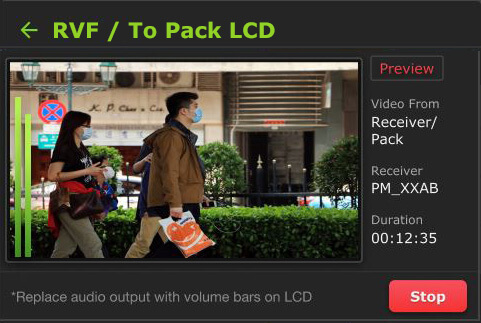
- Tap the Home button.
- The preview will be displayed on the Pack’s LCD screen.
- To stop the output, tap the Stop button.
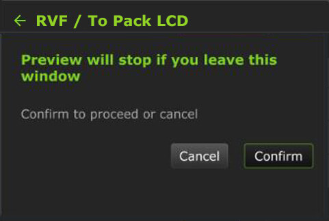
- If you navigate to another screen, the following message will be displayed. You can choose to Cancel or Confirm the operation.
To Pack’s LCD – From Producer
To set up RVF from a Producer session To Pack LCD:
- Tap the Main Setting menu > RVF button.
- In the To Pack LCD panel, tap Click here to set up.
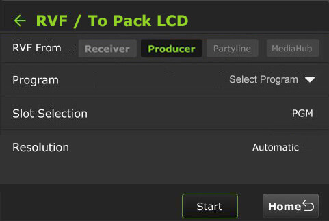
- The RVF / To Pack LCD screen will display.
- In the Video From panel, tap Producer.
- Select a Program from the Select Program drop-down menu.
- Tap Start.
- Tap the Home button.
- The preview will be displayed on the Pack’s LCD screen.
- To stop the output, tap the Stop button.
- If you navigate to another screen, the following message will be displayed. You can choose to Cancel or Confirm the operation.
To Pack’s LCD – From Partyline
To set up RVF from a Partyline session To Pack LCD:
- Tap the Main Setting menu > RVF button.
- In the To Pack LCD panel, tap Click here to set up.
- The RVF / To Pack LCD screen will display.
- In the RVF From panel, tap Partyline.
- Select a Partyline Source.
- Tap Start.
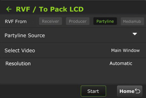
- Tap the Home button.
- The preview will be displayed on the Pack’s LCD screen.
- To stop the output, tap the Stop button.
- If you navigate to another screen, the following message will be displayed. You can choose to Cancel or Confirm the operation.
To Pack’s LCD – From MediaHub
To set up RVF from a MediaHub session To Pack LCD:
- Tap the Main Setting menu > RVF button.
- In the To Pack LCD panel, tap Click here to set up.
- The RVF / To Pack LCD screen will display.
- In the RVF From panel, tap MediaHub.
- Select a media from the drop-down menu.
- Tap Start.
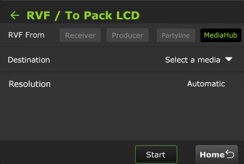
- Tap the Home button.
- The preview will be displayed on the Pack’s LCD screen.
- To stop the output, tap the Stop button.
- If you navigate to another screen, the following message will be displayed. You can choose to Cancel or Confirm the operation.
Upload
The Upload setting is accessed from the Settings gear icon > Main Setting menu > Upload button.
Using the Upload button, users can upload files from a USB flash drive to a Receiver:
- Tap the Upload tab.
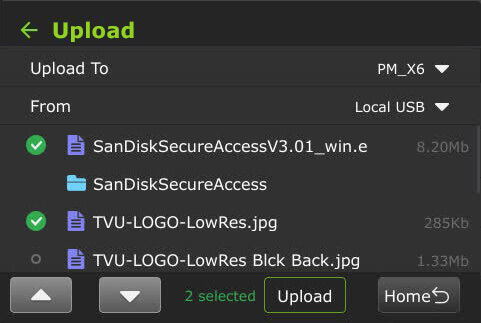
- Select a receiver from the Upload to drop-down list, then select a source in the From drop-down list.
- Select the files you want from the list.
- Tap Upload.
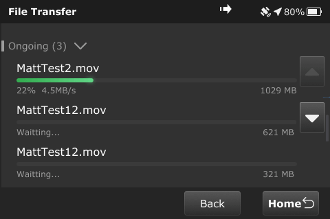
Transfer
The Transfer setting is accessed from the Settings gear icon > Main Setting menu > Transfer button.
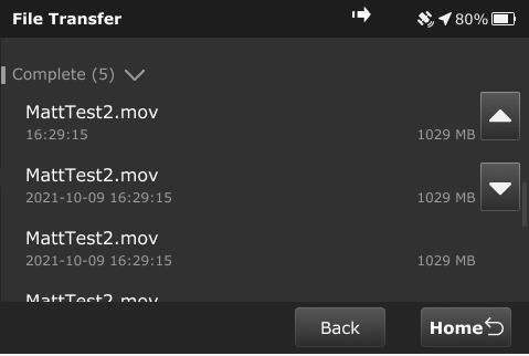
To view file transfer status, including progressive download, download, and auto-sync:
- Tap the Transfer button.
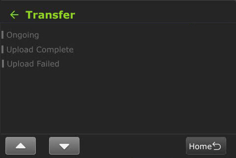
- The following status displays when the file transfer is ongoing.
- The following status displays when the file transfer is complete.
The following message appears when powering off the device if file transfers are in progress.

Speedtest
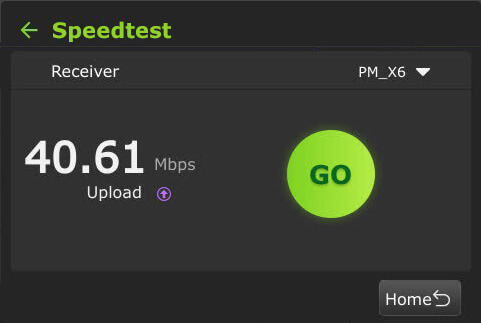
The Speedtest feature is a critical tool for ensuring your bonded cellular and satellite connections have enough combined bandwidth for a 4-camera HDR broadcast.
Unlike a standard smartphone speed test, the RPS One test specifically measures the uplink capacity to the TVU ecosystem.
To perform a speedtest:
- The Speedtest screen is accessed by tapping the Settings gear icon > Main Setting menu.
- Scroll down and tap the Speedtest button.
- The Speedtest screen will be displayed.
- Select a Receiver from the drop-down menu.
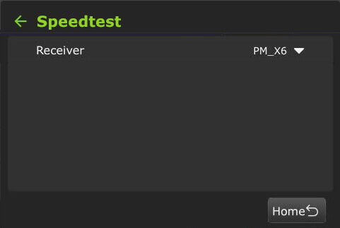
- Tap Go.
RPS One system status monitoring and control using a Web browser, iPhone, or smart mobile device
The RPS One encoder’s operational status can be monitored, and various transmission functions can be controlled from a Web browser. This interface can be accessed using a standard web browser connected to the RPS One hotspot.
Connecting to the RPS One hotspot
Complete the steps to connect a laptop or phone to the internal hotspot.
- Search for the hotspot on your iPhone/smart device. Then, when prompted, enter the case-sensitive SSID:
TVUPACK_XXXX
(Where X is the last 4 digits of the encoder’s PID)
The default password is the last 8 digits of the RPS One PID.
Note: All password characters are uppercase. The password can be changed in the Web UI if desired.
- Connect to the SSID using your iPhone or smart device. The following examples show how the status screens display on a smart device’s Web browser.
- Once the connection is established, you can open a web browser and enter http://192.168.4.1 in the address line to see the RPS One’s “System status.”
- The TVU RPS System status panel displays.
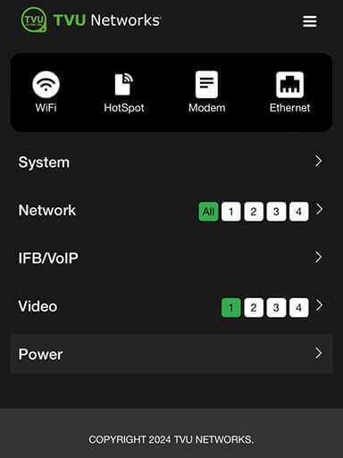
The System status screen provides detailed information on the System, Network, IFB/VoIP, and Video status.
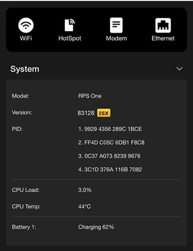
System panel
Expand the System caret to display System status, model, software version, and PID information.
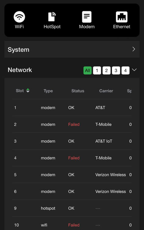
Network panel
The Network panel displays the current Network status.
IFB/VoIP panel – Audio Test
The IFB/VoIP panel allows the user to change the audio level of the IFB/VoIP function. Users can test the 3.5mm audio input and output interface hardware.
File management and recorded media progress can be accessed in the Advanced configuration File > Recorder tab.
To perform an Audio test, the device must be available and not in use for Live or VoIP/IFB.
To perform an Audio Test:
- Open the system status panel and expand the IFB/VoIP carat.
- Click the green Audio Test link.

- The Advanced > Audio Test page will open.
- Ensure the microphone and speaker are connected, then click OK.
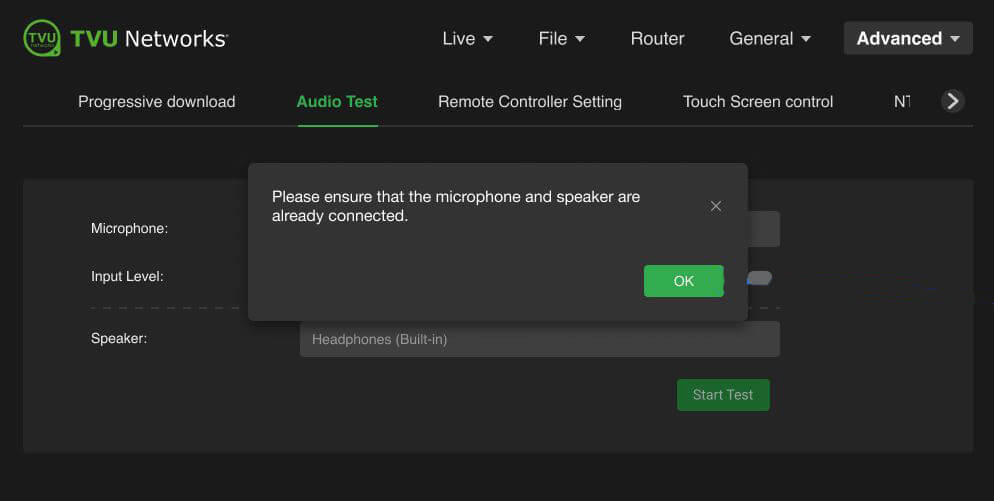
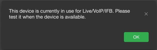
Note: If the device is currently in use for Live/VoIP/IFB, the following warning message appears.
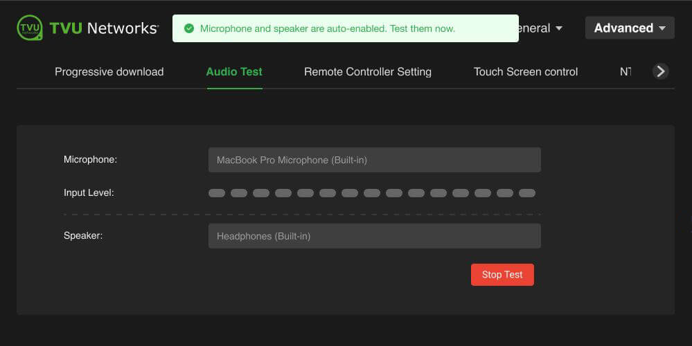
- Click Start Test.
- The default active microphone and speaker are auto-enabled message displays.
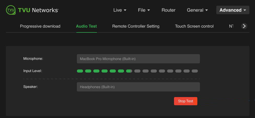
- Recording will start automatically when you enter this page. It will capture audio from the default microphone and display the input level on the green level bar. It will stop when you close or leave this page. If desired, you can click the Stop Test button to stop the recording.
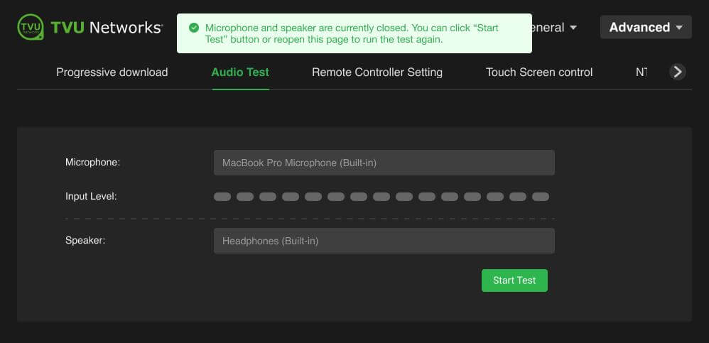
- To play the last recorded audio captured via the default microphone, click the Stop Test button again.
- To run the test again, click the Start Test button.
Video panel
The video panel displays information on video transmission and its status.
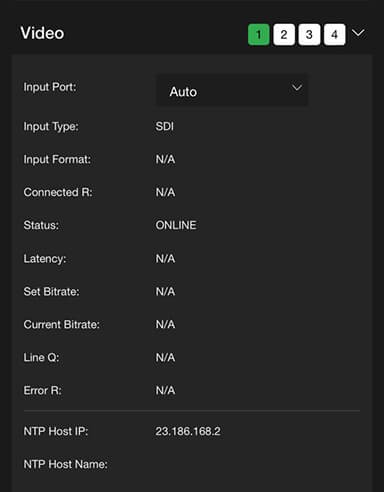
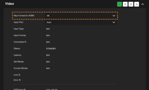
The Video panel now includes two input format options: 4K and 1080P. These formats allow Twitch streamers to choose the maximum input format for the HDMI setting to channel 1, allowing units to limit or configure the available Extended Delay Identification Data (EDID) resolutions. This feature enables forcing 1080P input detection via HDMI when a connected camera uses automatic resolution settings.
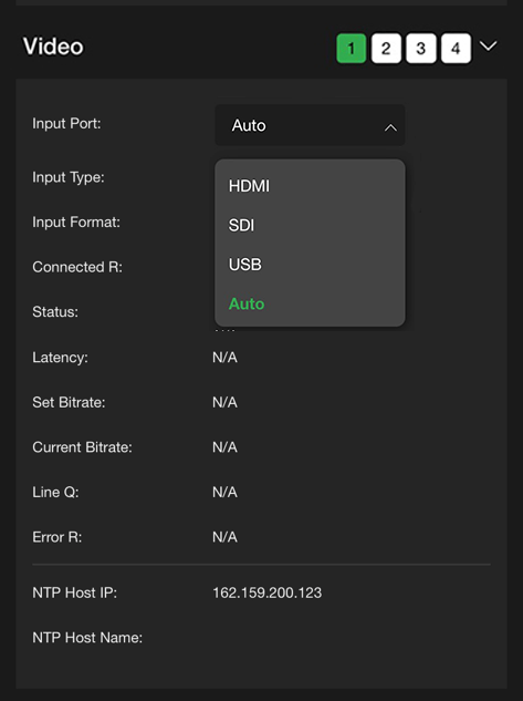
The Video panel allows users to select USB as the Input Port when the pack detects a USB video input source.
Supported USB cameras are:
- DJI Osmo Pocket 3 Pro
- DJI Osmo Action 5 Pro
- Logitech Brio 100
- Hikvision DS-U11
When selecting USB as a video input port, set 1080P30 as the Input format.
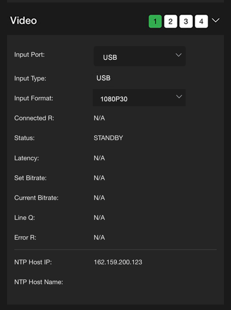
When the USB setting is successful, the USB input will be displayed at the top of the pack’s Home LCD touchscreen.
Return Video
This operation can be configured for the Receiver, Producer, Partyline, and MediaHub on the Pack’s LCD screen and in the Advanced operations configuration Live > Return Video screen.
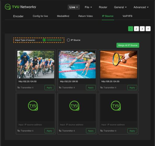
IP Source configuration
To configure the input source type for channel 1:
- Open the Web configuration menu.
- Click the Live menu, then the IP Source tab.
- Select channel 1, then click the HDMI/SDI/USB radio button.
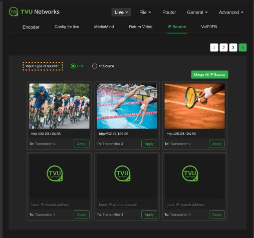
To configure the input source type for channels 2/3/4:
- Open the Web configuration menu.
- Click the Live menu, then the IP Source tab.
- Select channel 4, then click the SDI radio button.
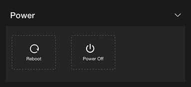
Power panel
The Power panel allows users to reboot and power off the pack.
Network configuration
To open the Network configuration panel:
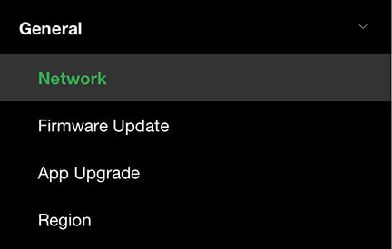
- Tap the three-bar icon to open the advanced operations panel.
- Tap the General drop-down menu and select Network. This allows users to navigate to, monitor, and control all aspects of transmission.
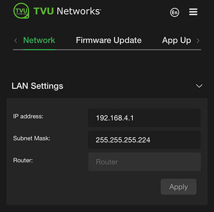
- In the LAN settings panel, set the RPS One’s local LAN address. The default IP address is 192.168.4.1.
- Enter the Subnet Mask and select a Router setting from the drop-down menu; the default is Auto.
- Click Apply.
- Use the following procedures to scroll through the remaining Network options to complete the configuration settings:
- Hotspot
- WiFi
- Ethernet
- Modems
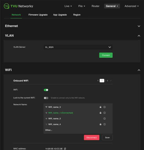
WiFi configuration and settings
The WiFi menu provides configuration information, access to change WiFi settings, and the ability to lock to the current WiFi network. The RPS One can optionally support multiple WiFi connections by purchasing optional hardware. For more information, contact TVU Networks support.
When multiple WiFi adapters are connected, you can scan available slots for WiFi adapters and configure WiFi login information using the RPS One WiFi setup and configuration panel.
Configuring WiFi
To configure your WiFi settings:
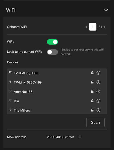
- Tap the WiFi icon.
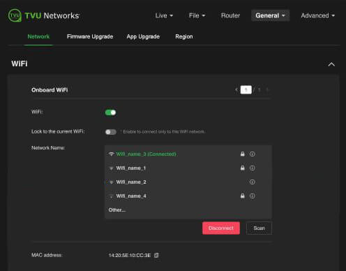
- Press the Scan button to display any available networks. The available networks are displayed in the center panel. Move the WiFi slider to the right to enable it.
- The WiFi network is disconnected by default, as shown below in the configuration screen, WiFi panel.
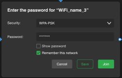
- Select the desired network from the center panel, then click the information “i” icon to connect to the WiFi. The settings pop-up window displays. Enter the Password.
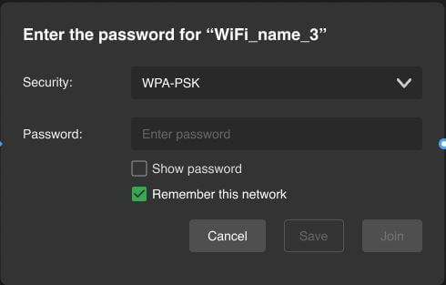
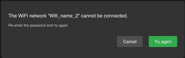
- If the password is incorrect, the following failure message displays.
- Click the Save button to save only the WiFi parameters, or the Join button to save and connect to the WiFi network.
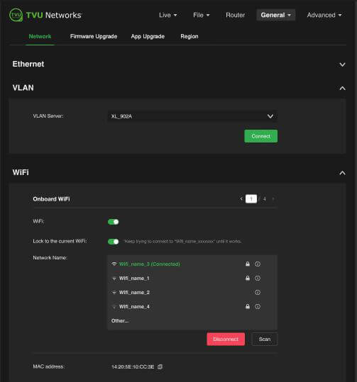
- If you choose Join to save and connect to WiFi, the following screen displays.
- To enable the Lock to current WiFi option, enable the slider. This option will automatically reconnect to the selected WiFi network if the signal drops.
- To switch to another WiFi network, disable the Lock to current WiFi slider.
- Select a WiFi connection, then enable the Lock to current WiFi slider.
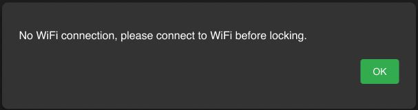
Note: If you enable the lock before connecting to another WiFi, the following message displays.
Router feature
Note: This feature must be enabled by support before it can be used.
To enable the Router feature:
- Tap the gear icon to open the Settings screen.
- The Main Setting menu will display.
- Tap the Router button.
- The Router screen will be displayed.
- By default, the router setting is off. Tap and move the router slider to the right until it turns green.
- When the router setting is in the on position, the following screen displays.
- To enable the Ethernet host setting, tap and move the Ethernet Host slider to the right until it turns green.
TVU Router feature (client connections)
If higher bandwidth is required when using a hotspot, the optional TVU Router feature can enable clients to connect to the RPS One at up to 200 Mbps.
- To access the Configuration page on an iPhone or other smart device, open a web browser and enter http://192.168.4.1.
- Tap the Hotspot icon to open the advanced operations panel.
- Tap the Network tab and expand the LAN Settings panel.
- Select Auto in the Router drop-down menu.
- Enter the IP address and Subnet Mask, then click Apply.
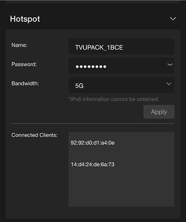
- Scroll down on the Hotspot panel. Connected Clients display in the Connected Clients device list.
USB remote control PTT button operations
- VoIP call operations
- SCTE insertion
Operators can now use a USB remote control as a Push-to-talk (PTT) button for the VoIP microphone. This allows users to mute and unmute their mic during a VoIP call independently of their headset.
Note: When attempting to click to another control mode while the mic is “Mute” a confirmation message appears. Click Yes to mute and change modes. The Mic will automatically reset.
VoIP call operations
To enable the VoIP call Mute/unmute feature:
- Open the local Web configuration page, click the Advanced menu, and the Remote Control Setting tab.
- Select the Mute/Unmute Mic in VoIP Call radio button.
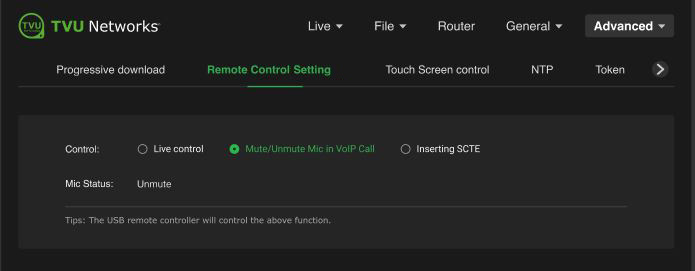
- Connect the USB remote controller device to the TVU Pack. While on a VoIP call, press once to mute.
- The Mic status shows Mute in red.
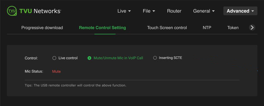
- Press again to unmute.
- When a VoIP microphone call invitation is received, the following message will appear automatically on the LCD touchscreen for 3 seconds.
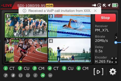
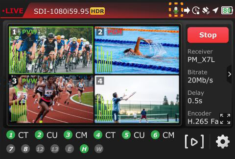
- When a VoIP call is connected, a white microphone icon appears at the top of the LCD screen.
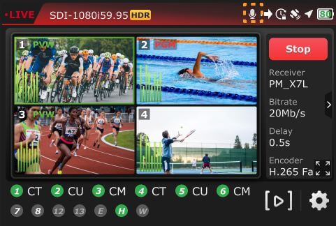
- When using VoIP, the Mic displays a modulating white-and-green icon.
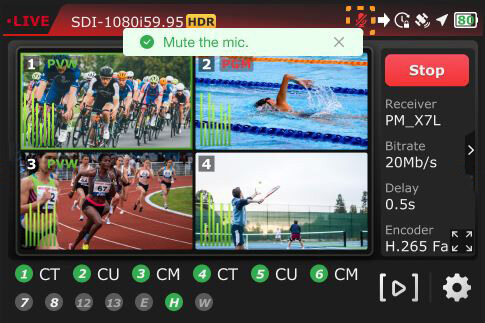
- When you press the remote button, a “Mute the mic” message appears, and the mic icon turns red, indicating that VoIP is connected and the mic is muted.
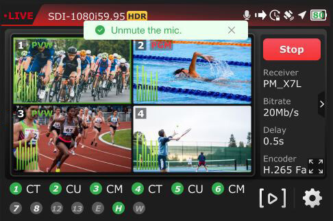
- Press the remote button again to unmute the mic. The mic icon will return to the white (connected and open) state.
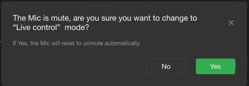
SCTE insertion
Note: If a user switches to Inserting SCTE while the Mic is Muted, a message will appear asking whether you want to switch to “Live control.” When this is allowed, the Mic will reset to Mute automatically.
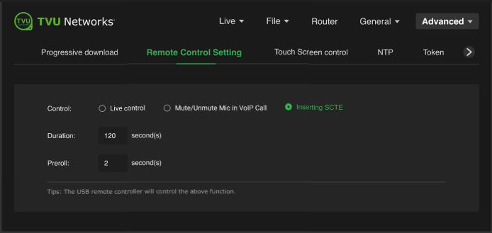
- Open the local Web configuration page, click the Advanced menu, and the Remote Control Setting tab.
- Select the Inserting SCTE radio button to set the control option.
Note: The Duration and Preroll SCTE default values that appear are editable.
- Plug the USB remote control device into the pack.
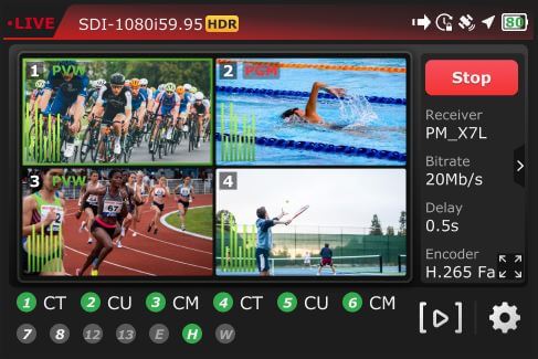
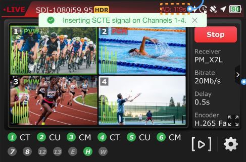
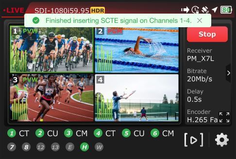
- Press the USB remote button once to begin inserting SCTE. The insertion automatically stops when the duration ends.
- The default duration value is 120 seconds. This value can be edited and will be saved after the pack reboots.
- The default Preroll value is 2 seconds. This value can be edited and will be saved after the pack reboots.
- The countdown displays at the top of the LCD screen.
- When the duration ends, the SCTE insertion automatically stops, and the following message displays.
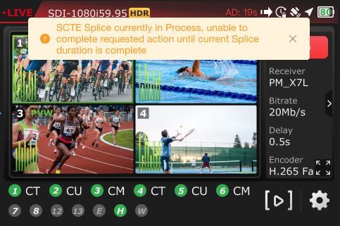
Note: If the user presses the Remote control device button while it’s active, an “SCTE Splice currently in process. Unable to complete the requested action until the current splice duration is complete” message displays on the LCD screen.
Resetting the Duration and Preroll parameters to default values
To change the SCTE parameters back to the SCTE default values:
- Open the Remote Control Setting page.
- Click the Inserting SCTE radio button.
- Click the Reset buttons to change to the default values.
RPS One Advanced configuration – Web interface controls
TVU RPS One hotspot settings
The hotspot panel provides status information about clients connected through the hotspot.
Configuring hotspot
To configure a hotspot:
- Tap the Hotspot icon.
Note: The Connected Client list window displays a list of devices that are connected using hotspots.
- To update the Password, edit the password field.
Note: The new password must be 8 characters and does not take affect until the system is restarted.
- The hotspot feature enables a connected device to access the Internet through one of the available network connections. This access allows file transfers via FTP or any other internet connection.
- You can manually select the route taken (for example, a Hotel WiFi network) by selecting the path from the WiFi panel.
- In the Bandwidth drop-down menu, choose 2.4 GHz or 5 GHz frequency.
- Click Apply to save your changes.
Modem configuration
The Modem panel provides modem configuration information to enable two modes: Manual and Auto. The transmitter automatically detects many cellular data cards and will self-configure when in Auto mode. If this is the case, no further action will be required. If a data card needs configuration, you can use the Modem panel to configure it by selecting the Manual roaming feature.
Auto mode
To enable Auto mode:
- Tap the Modem icon.
- The Modem panel opens.
- Select the Roaming for this modem checkbox and the Auto radio button.
- The Roaming for all modems checkbox will be checked by default.
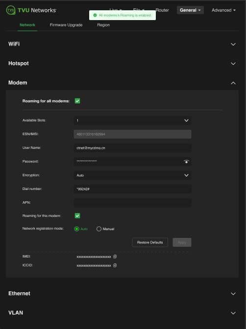
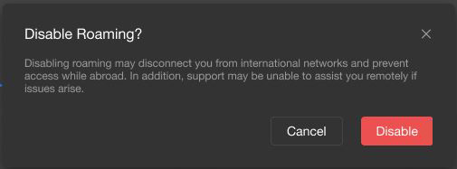
Note: If the “Roaming for this modem” box is unchecked, the following warning message appears.
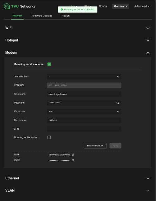
- If you choose to disable Roaming, the Roaming for slot XX is disabled message appears at the top of the panel.
- Users can change roaming for all modems by clicking the Restore Defaults button.
Manual roaming feature
The roaming for all modems is enabled by default.
The Manual radio button provides a global roaming toggle and an individual roaming switch for every slot. Changes to roaming settings (checked or unchecked) are saved automatically; clicking Apply is not necessary. Users can change roaming for all modems by clicking the Restore Defaults button.
To enable the Manual roaming feature:
- Tap the Modem icon.
- The Modem panel opens.
- Select the Roaming for all modems, Roaming for this modem, and Manual.
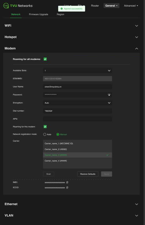
- Click the Scan button to load the Carrier panel.
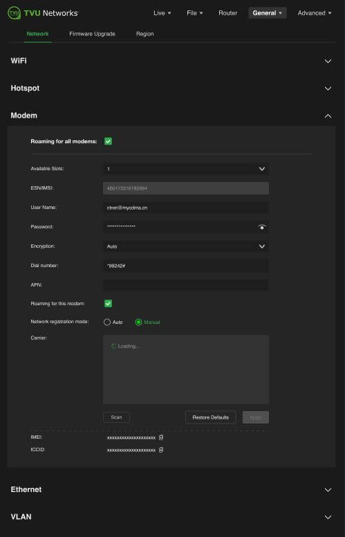
- Select a Carrier from the list and click Apply.
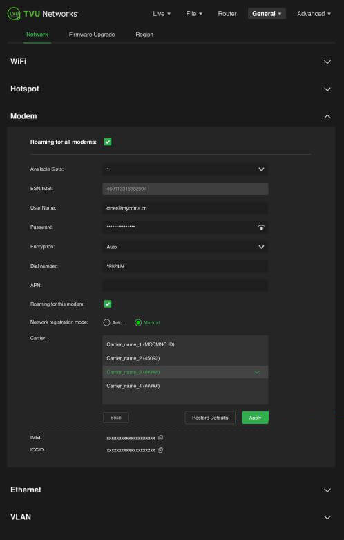
- When successful, the Applied successfully confirmation appears at the top of the panel.
- To turn global Roaming off, uncheck the Roaming for all modems checkbox. The Disable Roaming warning message appears.
- Click the Disable button.
- The All modems Roaming is disabled confirmation appears at the top of the panel.
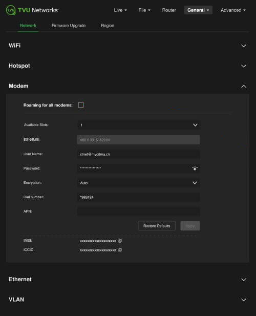
Configuring data cards
To configure specific data cards:
- Click the Available Slots drop-down menu to display a list of available slots for configuration.
- If Manual configuration is required, input the settings provided by your carrier into the Network registration mode panel.
- Click Apply to save any changes.
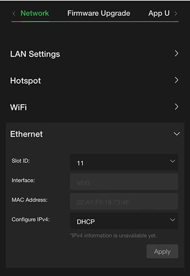
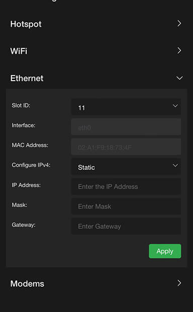
Ethernet configuration DHCP IP
Ethernet settings are accessed and configured from the System configuration Home panel.
Note: The DHCP IP address is automatically generated and cannot be manually entered.
To configure your Ethernet settings for a DHCP IP address:
- Open the Web browser UI and tap the Ethernet icon.
- Tap the Configure IPv4 drop-down menu and select DHCP.
- Tap the Slot ID drop-down menu and select a slot number.
- Tap Apply.
Ethernet configuration Static IP
To configure your Ethernet settings for a Static IP address:
- Tap the Configure IPv4 drop-down menu and select Static IP.
- Tap the Slot ID drop-down menu and select a slot number.
- Enter a Static IP address in the IP Address field.
- Enter the Subnet Mask in the Mask field.
- Enter the Gateway in the Gateway field.
- Tap the Apply button to save your changes.
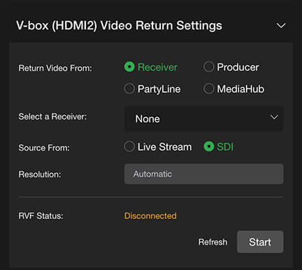
Live tab – Return Video
For the V-Box adapter, if the resolution of the return video from the receiver is 1080P or higher and the bitrate exceeds 2M, users can lower the resolution by selecting the appropriate Resolution and Bitrate in the drop-down menu.
Updating the return video resolution
To update the V-box adapter return video resolution:
- Open the Advanced configuration screen.
- Open the Live > Return Video panel and choose the appropriate Resolution.
- Open the Receiver tab and choose the appropriate Bitrate.
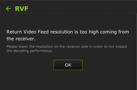
Note: If the RVF feed resolution is too high, the following message appears on the LCD touchscreen.
Live tab – VoIP Audio inputs
Version 8.2 and higher of the receiver and pack support real-time switching between VoIP and IFB calls.
Note: A device reboot is required when switching between VoIP and IFB if the receiver version is lower than v8.2.
The Audio setting option only applies to VoIP, if it is IFB, these options are not available.
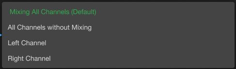
Audio encoding mode – 2 -channel option
Mixing all Channels is set as the default option when selecting any transmitter.
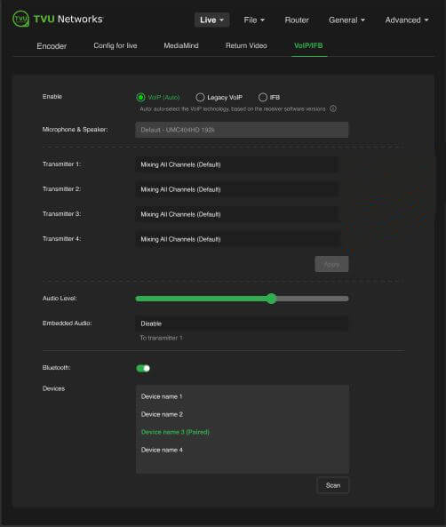
When a specific channel is chosen, such as “Left Channel” or “Channel 1”, the other three transmitters will default to “Left Channel” or “Channel 1.” Users can manually adjust these transmitters as needed to send other individual Audio Channels.
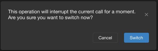
The Apply button is only applicable for these settings. If nothing has changed, the Apply button will appear as grayed out. When in a call, switching the call mode will prompt the following confirmation dialog to remind users that the operation will interrupt the current call.
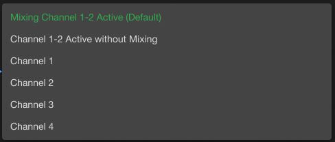
Audio encoding mode – 4-channel option
When the without mixing option is selected in any transmitter, the other three transmitters will automatically synchronize to it.
When in a call, switching the call mode will prompt the following confirmation dialog to remind users that the operation will interrupt the current call.
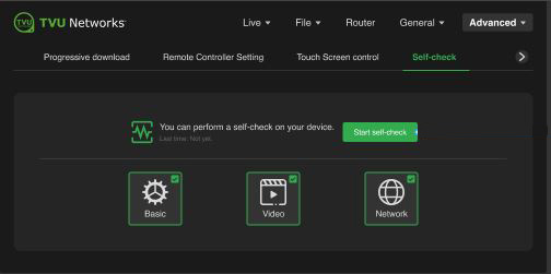
Advanced Self-Check panel
The Advanced Self-Check panel enables you to self-check your devices’ basic, video, and network health status while the device is not live. TVU Support staff can use this information for troubleshooting purposes.
To perform a self-check on your device in the Advanced configuration panel:
- Open the Advanced configuration UI.
- Tap the Advanced menu and select the Self-Check tab.
- To run diagnostics on your device, tap one or all of the Basic, Video, and Network checkboxes, then tap the Start self-check button.
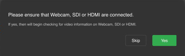
- The following pre-check prompts display when selected in Step 1.
- Tap Yes to confirm the Video check prompt.
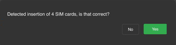
- Tap Yes to confirm the Network check prompt.
- The Self-Check window displays its status.
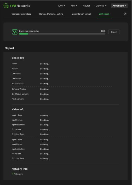
- The Self-Check results display errors when completed. The errors are displayed in red.
- Address any errors and tap the Self-check again button.
- The Self-Check report will display no red errors when complete.
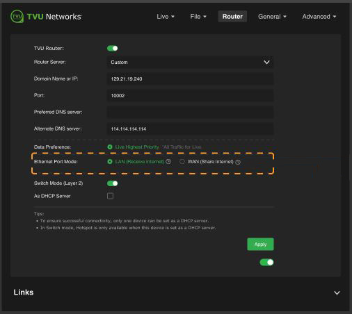
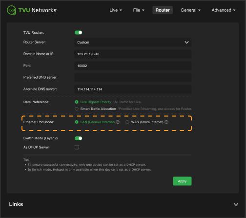
Router configuration
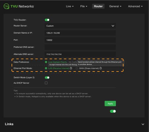
The Run Router Live Together feature makes it easy for users to define (WAN) Router mode vs. (LAN) pass-through or receive mode. Ethernet Port Mode includes a WAN (share internet) radio button that sends bonded cellular internet through the Ethernet port. The LAN (Receive internet) radio button will accept incoming internet through the Ethernet port.
To open the Router configuration panel:
- Tap the three-bar icon or the Web UI to open the advanced operations panel.
- Select Router. The Router panel will be displayed.
- Enable the TVU Router slider.
- The Ethernet Port Mode radio button is set to WAN (Share internet) by default.
- Mouse over the radio buttons to display their behavior.
- When the Run Router Live Together feature is enabled, the router panel displays the Smart Traffic Allocation radio button under Data Preference. This button will prioritize Live streaming and use the excess for the router.
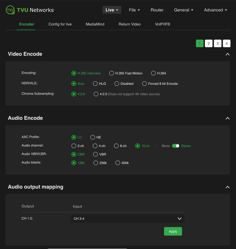
Audio Encoding – Stereo
To set the Audio Encoding to Stereo (default):
- Click the Live > Encoder tab.
- Enable the 16-Ch radio button and move the slider from Mono to Stereo in the Audio Encode panel.
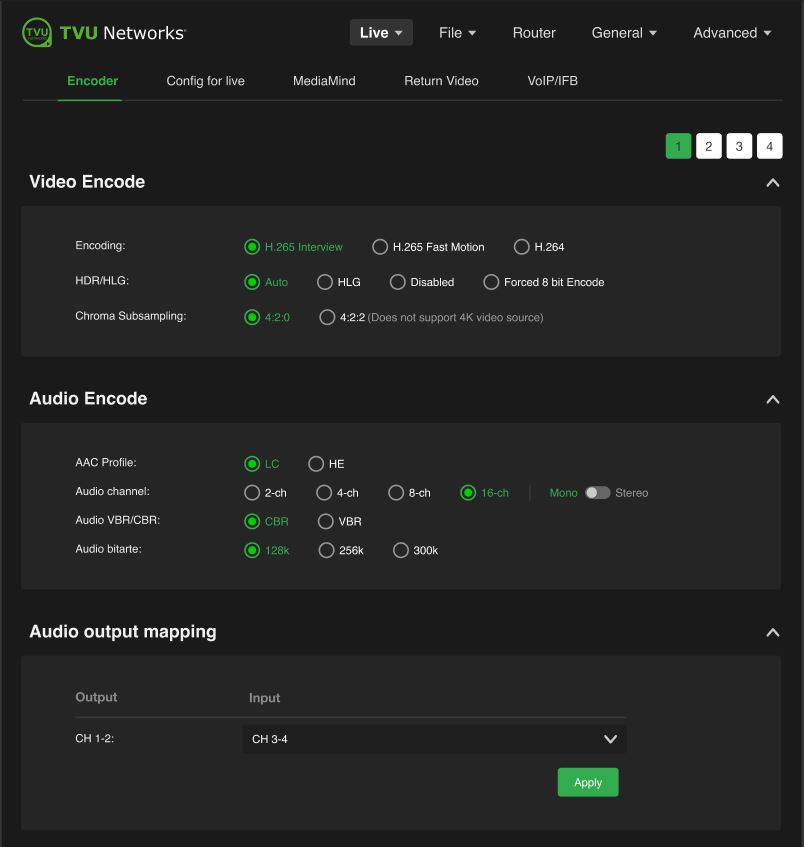
Audio Encoding – Mono
To set the Audio Encoding to Mono:
- Click the Live > Encoder tab.
- Enable the 16-Ch radio button and move the slider from Stereo to Mono in the Audio Encode panel.
© Copyright 2026 TVU Networks Corporation. All rights reserved in all media.
Document Part Number: TVU RPS One Model TM1100 Software QGUG Rev G EN 02-2026